
Control Two Stepper Motors Using Rotary Encoder Sensor & Ard

About the project
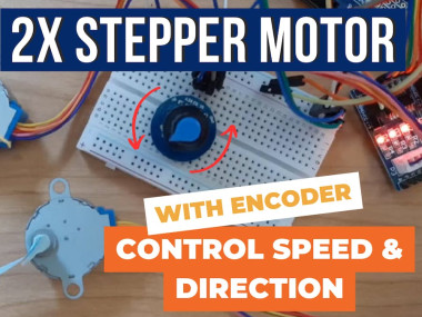
In this simple tutorial we will learn how to control 2 stepper motors using a rotary encoder sensor & Arduino. Watch the Video!
Project info
Difficulty: Easy
Platforms: Arduino, Digilent, Visuino
Estimated time: 1 hour
License: GNU General Public License, version 3 or later (GPL3+)
Items used in this project
Hardware components

Story
1 / 6
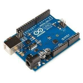
- Arduino UNO (or any other board)
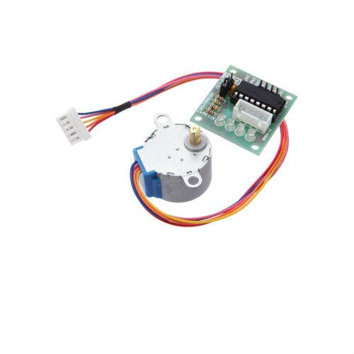
- 2X Stepper motor 28byj-48 & stepper motor driver board
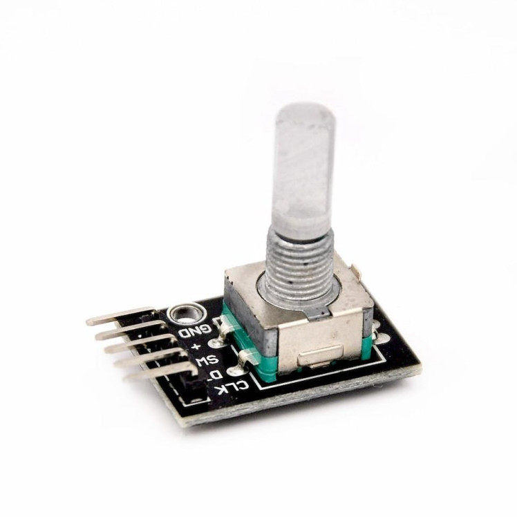
- Rotary Encoder Sensor
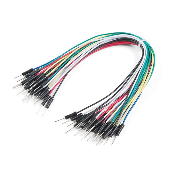
- Jumper wires
- Visuino program: Download Visuino
1 / 2


Thank you PCBWay for supporting this tutorial and helping users learn more about electronics.
NEW! Now you can get Aluminum PCB & FLEX PCB in their Special Offer!
What I like about the PCBWay is that you can get 10 boards for approximately $5 which is really cost effective for professional made boards, not to mention how much time you save!
Go check them out here. They also offer special discounts celebrating their 9th anniversary More info here.
Step 3: The Circuit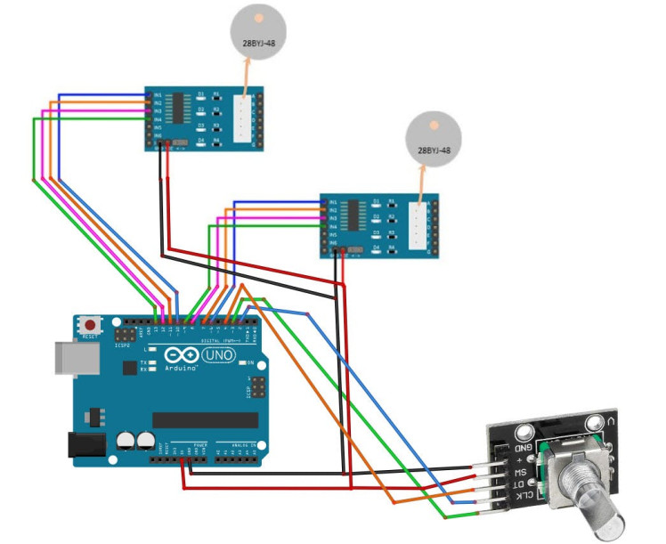
- Connect Arduino pin [5V] to Driver Board1 pin [VCC]
- Connect Arduino pin [GND] to Driver Board1 1pin [GND]
- Connect Arduino digital pin [6] to Driver Board1 pin [IN1]
- Connect Arduino digital pin [7] to Driver Board1 pin [IN2]
- Connect Arduino digital pin [8] to Driver Board1 pin [IN3]
- Connect Arduino digital pin [9] to Driver Board1 pin [IN4]
- Connect Arduino pin [5V] to Driver Board2 pin [VCC]
- Connect Arduino pin [GND] to Driver Board2 1pin [GND]
- Connect Arduino digital pin [10] to Driver Board2 pin [IN1]
- Connect Arduino digital pin [11] to Driver Board2 pin [IN2]
- Connect Arduino digital pin [12] to Driver Board2 pin [IN3]
- Connect Arduino digital pin [13] to Driver Board2 pin [IN4]
Connecting Encoder module:
- Connect Encoder module pin [CLK] to Arduino digital pin [2]
- Connect Encoder module pin [DT] to Arduino digital pin [3]
- Connect Encoder module pin [SW] to Arduino digital pin [4]
1 / 2
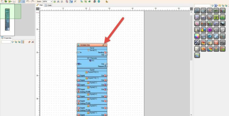
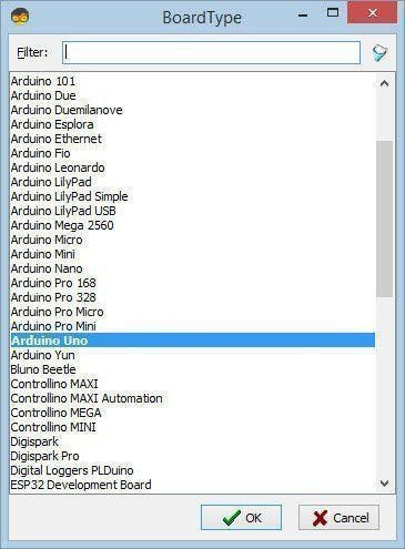
Start Visuino as shown in the first picture Click on the "Tools" button on the Arduino component (Picture 1) in Visuino When the dialog appears, select "Arduino UNO" as shown on Picture 2
Step 5: In Visuino Add Components1 / 6
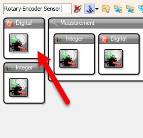

- Add "Rotary Encoder Sensor" component
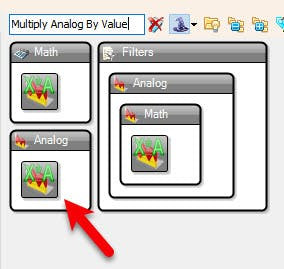
- Add "Multiply Analog By Value" component
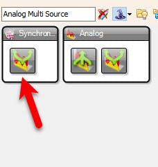
- Add "Analog Multi Source" component
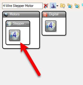
- Add 2X "4 Wire Stepper Motor" component
- Add "Toggle(T) Flip-Flop" component
1 / 3
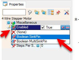
- Select "Stepper1" and in the properties window select "Enabled" click on the pin icon and select "Boolean SinkPin"
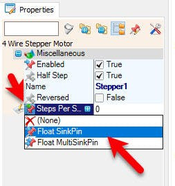
- Select "Stepper1" and in the properties window select "Steps Per Second" click on the pin icon and select "Float SinkPin"
- Select "Stepper2" and in the properties window select "Enabled" click on the pin icon and select "Boolean SinkPin"
- Select "Stepper2" and in the properties window select "Steps Per Second" click on the pin icon and select "Float SinkPin"
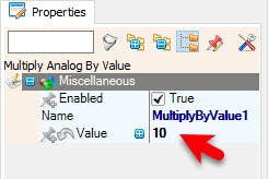
- Select "MultiplyByValue1" and in the properties window set "Value" to 10
1 / 2
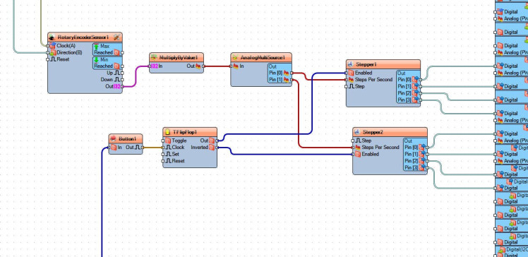
- Connect Arduino digital pin [2] to "RotaryEncoderSensor1" pin [Direction]
- Connect Arduino digital pin [3] to "RotaryEncoderSensor1" pin [Clock]
- Connect "RotaryEncoderSensor1" pin [Out] to "MultiplyByValue1" pin [In]
- Connect "MultiplyByValue1" pin [Out] to "AnalogMultiSource1" pin [In]
- Connect "AnalogMultiSource1" pin [0] to "Stepper1" pin [Steps Per Second]
- Connect "AnalogMultiSource1" pin [1] to "Stepper2" pin [Steps Per Second]
- Connect Arduino digital pin [4] to "Button1" pin [In]
- Connect "Button1" pin [Out] to "TFlipFlop1" pin [Clock]
- Connect "TFlipFlop1" pin [Out] to "Stepper1" digital pin [Enabled]
- Connect "TFlipFlop1" pin [Inverted] to "Stepper1" digital pin [Enabled]
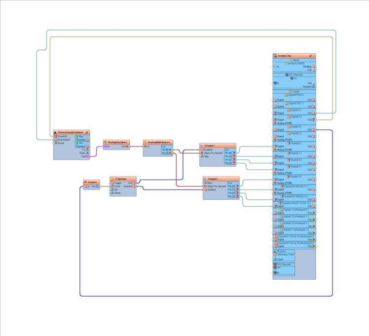
- Connect "Stepper1" pin [0] to Arduino digital pin [6]
- Connect "Stepper1" pin [1] to Arduino digital pin [7]
- Connect "Stepper1" pin [2] to Arduino digital pin [8]
- Connect "Stepper1" pin [3] to Arduino digital pin [9]
- Connect "Stepper2" pin [0] to Arduino digital pin [10]
- Connect "Stepper2" pin [1] to Arduino digital pin [11]
- Connect "Stepper2" pin [2] to Arduino digital pin [12]
- Connect "Stepper2" pin [3] to Arduino digital pin [13]
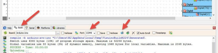
In Visuino, at the bottom click on the "Build" Tab, make sure the correct port is selected, then click on the "Compile/Build and Upload" button.
Step 9: PlayIf you power the Arduino module and rotate the rotary encoder sensor the Stepper Motor will start to rotate in forward direction or reversed direction and if you press the button on the rotary encoder sensor the second motor will start to rotate.
Congratulations! You have completed your project with Visuino. Also attached is the Visuino project, that I created for this Project, you can download it here and open it in Visuino: https://www.visuino.eu
Schematics, diagrams and documents
Code
Credits
Related products


Leave your feedback...