
Control Leds On/off With 433mhz Rf Remote And Arduino

Made by Ron / Communication / Robotics / Security / IoT
About the project
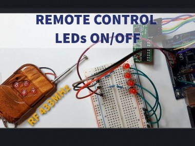
In this simple tutorial we will learn how to turn ON/OFF 4 LEDs with a 433MHz RF Remote and Arduino. Watch the Video!
Project info
Difficulty: Easy
Estimated time: 1 hour
License: GNU General Public License, version 3 or later (GPL3+)
Items used in this project
Hardware components

Story
In this simple tutorial we will learn how to turn ON/OFF 4 LEDs with a 433MHz RF Remote and Arduino.
Watch the Video!
Step 1: What You Will Need
1 / 5

- Arduino UNO (or any other Arduino)
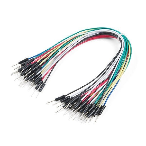
- Jumper wires
- 4 X LED
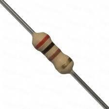
- 4 X 1K ohm Resistor
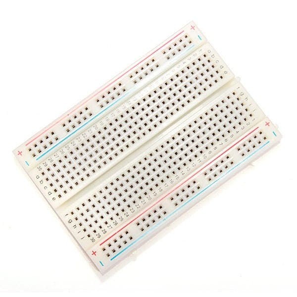
- Breadboard
- 433 MHz RF module
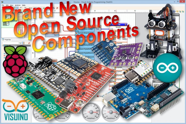
- Visuino program: Download Visuino
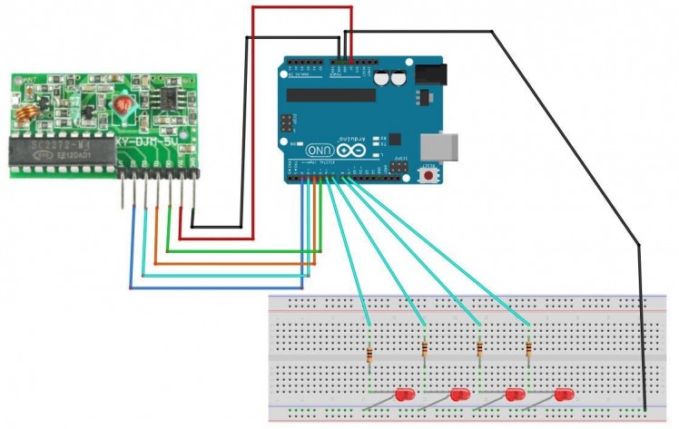
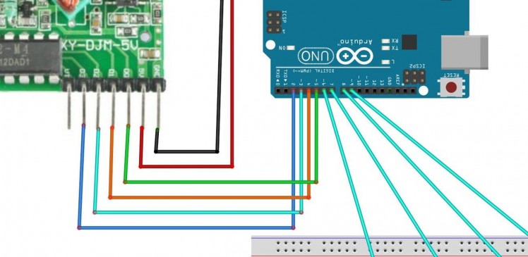
- Connect Remote pin [VCC] to Arduino pin [5V]
- Connect Remote pin [GND] to Arduino pin [GND]
- Connect Remote pin [D0] to Arduino digital pin [2]
- Connect Remote pin [D0] to Arduino digital pin [3]
- Connect Remote pin [D0] to Arduino digital pin [4]
- Connect Remote pin [D0] to Arduino digital pin [5]
- Connect Arduino digital pin [6] to Breadboard 1KOhm resistor1
- Connect Arduino digital pin [7] to Breadboard 1KOhm resistor2
- Connect Arduino digital pin [8] to Breadboard 1KOhm resistor3
- Connect Arduino digital pin [9] to Breadboard 1KOhm resistor4
- Connect Arduino pin [GND] to Breadboard blue line pins [GND]
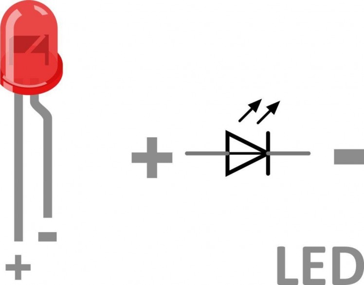
- Connect Breadboard 1KOhm resistor1 pin to LED1 positive pin
- Connect Breadboard 1KOhm resistor2 pin to LED2 positive pin
- Connect Breadboard 1KOhm resistor3 pin to LED3 positive pin
- Connect Breadboard 1KOhm resistor4 pin to LED4 positive pin
- Connect LED1 negative pin to Breadboard blue line pin [GND]
- Connect LED2 negative pin to Breadboard blue line pin [GND]
- Connect LED3 negative pin to Breadboard blue line pin [GND]
- Connect LED4 negative pin to Breadboard blue line pin [GND]
1 / 2
The Visuino: https://www.visuino.eu also needs to be installed. Download Free version or register for a Free Trial.
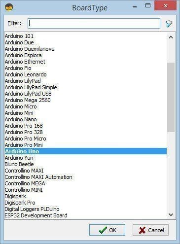
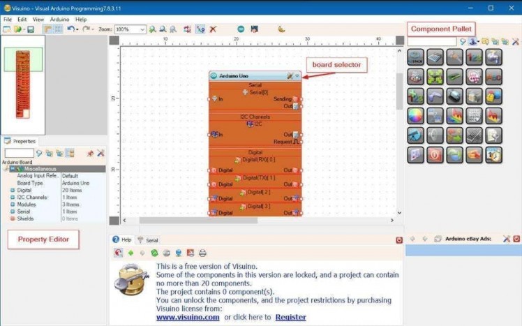
Start Visuino as shown in the first picture Click on the “Tools” button on the Arduino component (Picture 1) in Visuino When the dialog appears, select “Arduino UNO” as shown on Picture 2
Step 4: In Visuino Add, Set & Connect Components
1 / 2
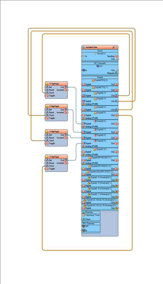
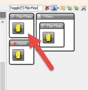
- Add 4X “Toggle(T) Flip-Flop” component
This components will act as a switch, whenever it gets a signal to “Clock” pin it will switch from True to False or from False to True
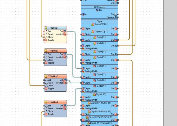
- Connect Arduino digital Out pin [2] to “TFlipFlop1” pin “Clock”
- Connect Arduino digital Out pin [3] to “TFlipFlop2” pin “Clock”
- Connect Arduino digital Out pin [4] to “TFlipFlop3” pin “Clock”
- Connect Arduino digital Out pin [5] to “TFlipFlop4” pin “Clock”
- Connect “TFlipFlop1” pin [Out] to Arduino digital pin [6]
- Connect “TFlipFlop2” pin [Out] to Arduino digital pin [7]
- Connect “TFlipFlop3” pin [Out] to Arduino digital pin [8]
- Connect “TFlipFlop4” pin [Out] to Arduino digital pin [9]
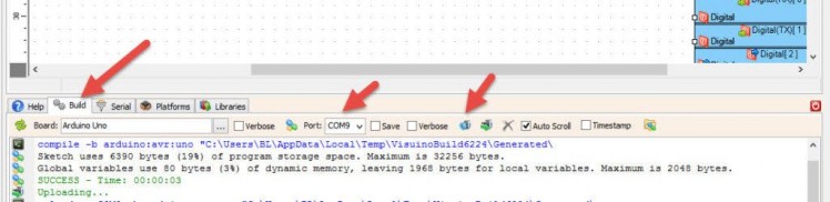
In Visuino, at the bottom click on the “Build” Tab, make sure the correct port is selected, then click on the “Compile/Build and Upload” button.
Step 6: PlayIf you power the Arduino module, and press the button on the Remote the LED will Turn ON or OFF.
Congratulations! You have completed your project with Visuino. Also attached is the Visuino project, that I created for this Tutorial, you can download it and open it in Visuino: https://www.visuino.eu
Download REMOTE-LED.zip
Schematics, diagrams and documents
Code
Credits
Related products


Leave your feedback...