
Cellular R.o.b With Blues Wireless!

Made by zfields / Games & Gaming / Retro Tech / Robotics / Upcycling / IoT
About the project
The ability to control R.O.B. left with CRT televisions; until now! Blues Wireless breathes new life with remote instructions over cellular!
Project info
Difficulty: Moderate
Platforms: Autodesk, SparkFun, Blues Wireless
Estimated time: 7 hours
License: MIT license (MIT)
Items used in this project
Hardware components

View all
Software apps and online services
View all
Story
As I was walking through my local flea market, I saw him. I wasn't sure if it was actually him at first, but as I got closer all the childhood memories came flooding back! I never had a R.O.B. when I was a kid, in fact, I had only seen him once that I can ever recall.
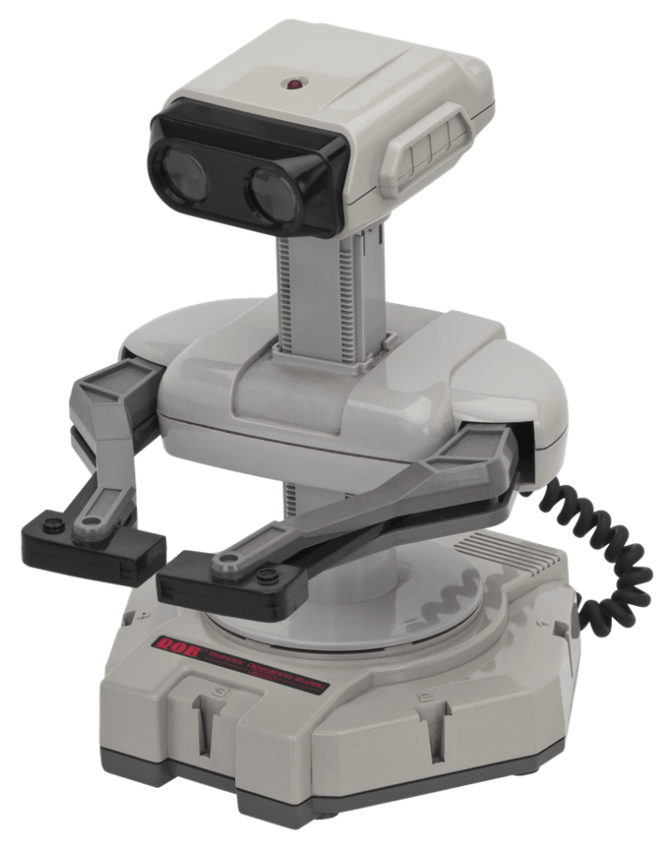
I had ALWAYS wanted to play with one, and now I finally had my chance! As soon as I got home, I started researching R.O.B. to see how he is supposed to work. You can imagine my disappointment, when I discovered he only works on two games, Gyromite and Stack-Up, and only with a CRT television. I'm not really sure what I was expecting to find, but my heart sank.
As I continued reading, I stumbled across Adafruit's Blog and how people had learned to control R.O.B. by emulating NTSC signals using LEDs. Eureka! What an amazing discovery! Now I was back in my wheelhouse, a place I where I am comfortable, and I was certain there would still be fun to be had with R.O.B!
Preliminary ResearchI read the Adafruit blog post end-to-end, and it turns out R.O.B. has a photosensor in his left eye that is connected to a integrated circuit in his head. The IC in R.O.B.'s head sends instructions to a microcontroller on his motherboard, which allows him to respond to your commands. In other words, R.O.B. works by actually watching you play video games, then plays along with you! This is 1985 we are talking about... Unbelievable!
Adafruit offered a Python implementation for use with their Circuit Playground Express, but I was looking for a standard Arduino sample and there wasn't anything to be found. The Adafruit blog made reference to the Atari Age Forums, and specifically a thread about reverse engineering R.O.B.
The thread goes into great detail about the signals required for each command. There was also a partial C implementation that the author was never quite able to get working. I continued searching even the most obscure posts, but I never found any working C code to control R.O.B. Well, I happen to be a utility/driver programmer by trade, and knew this is where I could make my contribution!
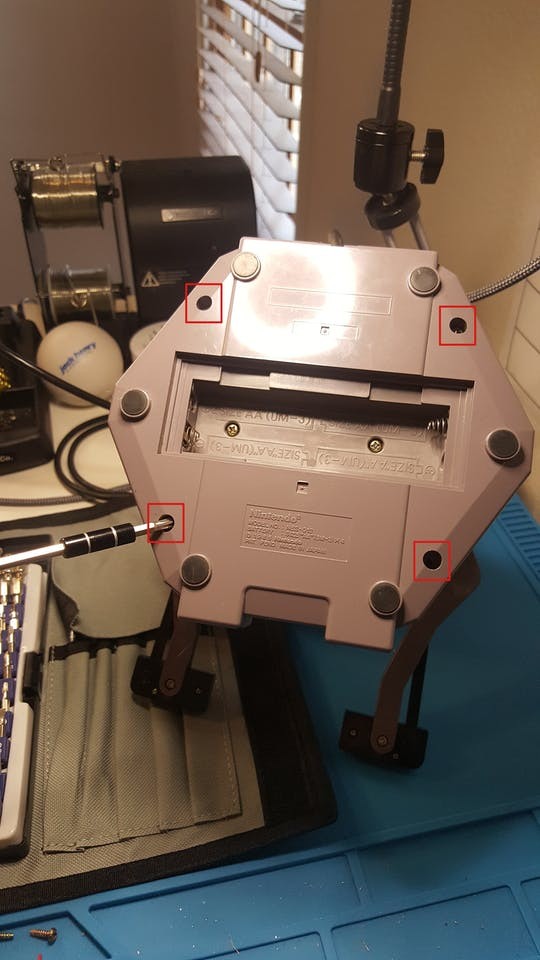
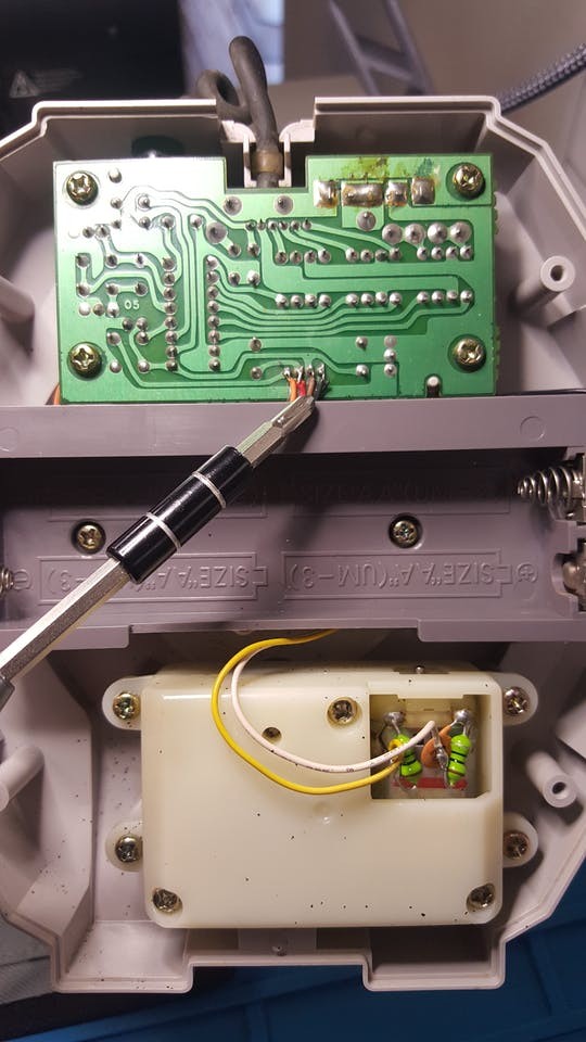
Picking R.O.B.'s BrainAs I mentioned before, R.O.B. has an IC in his head and an MCU on the motherboard in his base. There is a 4-wire ribbon cable running between the two chips, which could easily be thought of as a brainstem. What better place to take a deeper look into what R.O.B. is thinking?
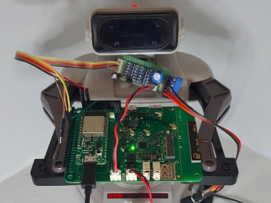
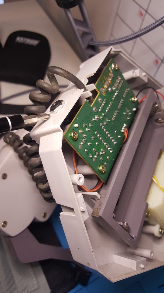
R.O.B. Motherboard

R.O.B. Motherboard
Fortunately, R.O.B. is a product of his time, and he uses a large, single layer PCB, with giant components. The ribbon cable is clipped into the motherboard, which made for an easy place to connect my oscilloscope.
As I expected, when R.O.B. received input from an LED, then the IC in his head would send a signal down the brainstem to the MCU on his motherboard. The signal consisted of a unique marker sent at well-defined intervals. It took me longer to realize than I would like to admit, but the interval timing mirrored the timing of the LED pulses. However, instead of being a light pulse, it was a unique square wave.
Oscilloscope Timing of Marker SIgnal

Oscilloscope Timing of Marker SIgnal
After identifying the W-shaped square wave and fully understanding the timing, I had everything I needed to create an open-source library. Upon completion of the library, I submitted a PR to the Arduino library repository, and the NesRob library can be downloaded to an Arduino via the Arduino Library Manager. If you are interested, the source code as well as the full details of my research are available on GitHub.
While working through the library, I quickly noticed that using an LED was unreliable. It felt like there were too many variables, such as the brightness and placement of the LED, ambient lighting, etc., so I started looking for a better solution. Others have gone as far as to make goggles for R.O.B. (which are proprietary, but admittedly rather neat), but I am of the opinion that most solutions of this nature are too fragile and too clunky to be practical. My only limitation was that I am unwilling to modify R.O.B. in such a way that he could no longer function as he was originally designed.
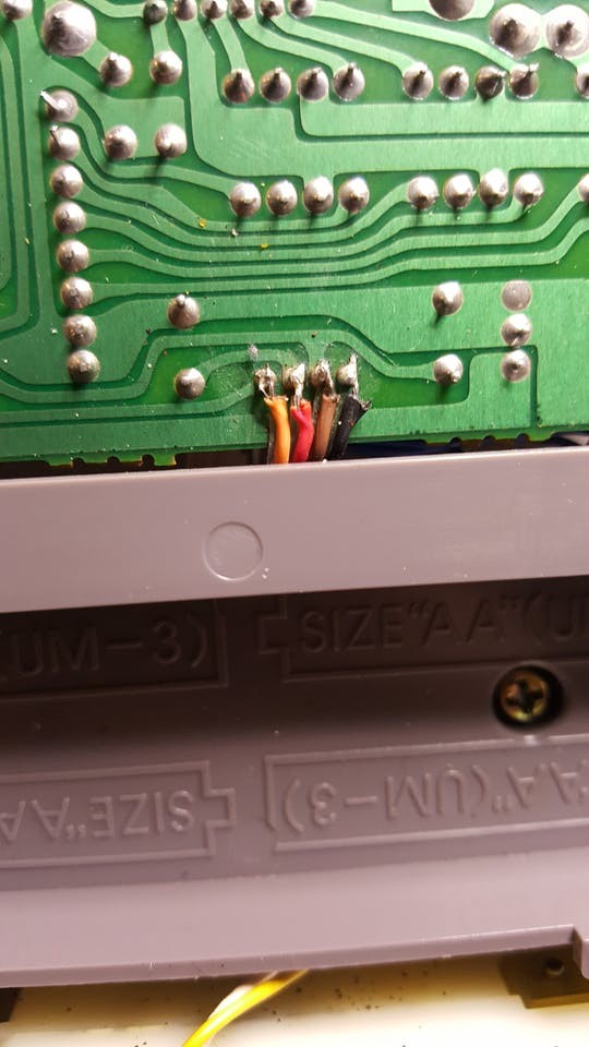
I studied the PCB, and the solution became obvious. I could connect to the back side of the brainstem connector on the motherboard. There is plenty of void space in R.O.B.s base, which provides plenty of room for a solution. The brainstem has four wires labeled G, S, V, and L, which apparently stand for (G)round, (S)ignal, (V)oltage and (L)ED, respectively. Two types of four-pin, panel-mount connectors came to mind, an RJ-45 (or phone jack) and a 3.5mm TRRS (a.k.a. headphones jack). The footprint of the TRRS cable is much smaller than the RJ-45, so the decision was easy.
1 / 7 • Brainstem Access Port

Brainstem Access Port
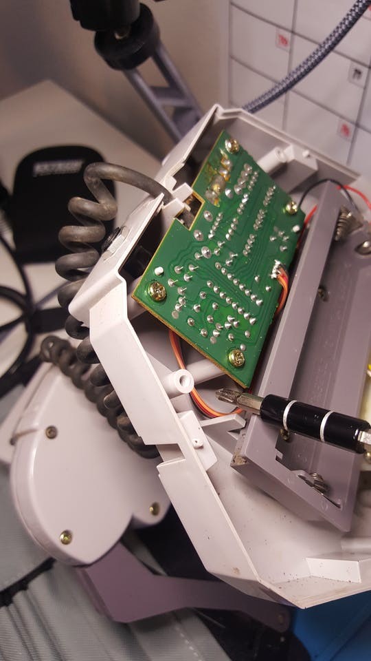
By creating the Brainstem Access Port, I was able to achieve both of my goals. First and foremost, it did not alter the way R.O.B. receives signals from his "eye". Second, R.O.B. now has a hard-wired port capable of providing reliable communication, and as an added bonus, we now have access to his battery pack. Ergo, R.O.B. can be used as a battery and robotic peripheral for an IoT project! Then when he's not "working", he can still sit beside you, watch you play Gyromite, and play right alongside you.
Speaking R.O.B.'s LanguageNow that we have access to R.O.B.s communication channel and his power supply, then getting him to do what we want should be easy, right? Well, sorta.
R.O.B. was designed around 4 AA batteries. AA batteries provide approximately 1.5V each, but this can vary up or down based on the level of charge. The (V)oltage line runs at about 6V (or 4 x 1.5V) and the (S)ignal line is held high at the same voltage, but the (L)ED runs just under 2V.
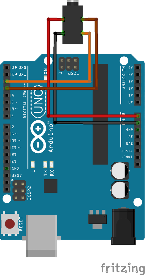
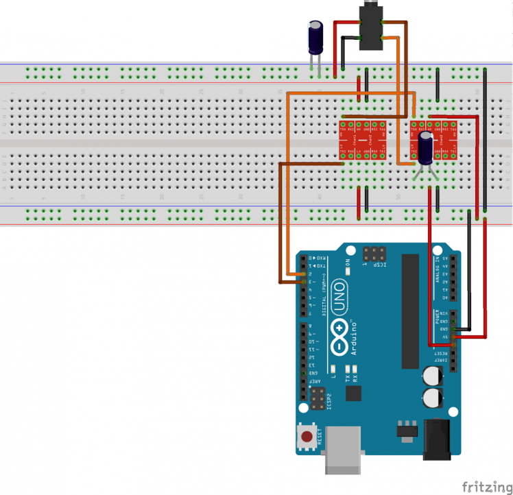
A classic Arduino Uno runs at 5V and is built for abuse, so it can tolerate the 6V signal (at least temporarily). Theoretically, an Uno could be connected directly to R.O.B. and provide control without any additional hardware. However, all the newer Arduino boards are starting to run on 3.3V. With that in mind, I decided to make a more robust solution capable of supporting almost any board. So, I purchased some logic level converters to bridge the voltage divide between R.O.B. and the controlling MCU.
1 / 6 • Arduino Uno direct wired

Arduino Uno direct wired

Arduino Uno with Logic Level Converters

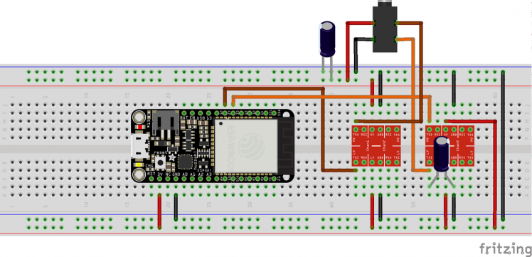
ESP32 with Logic Level Converters
At this point, we have direct, hard-wired access to R.O.B.'s motherboard, and the ability to manipulate him from any common microcontroller.
Ground Control to Major R.O.B.As with any robotic peripheral, R.O.B. has limited utility without external influence. In other words, R.O.B. needs to respond to remote control in order to become interesting. On that note, I recently received my Blues Wireless Feather Starter Kit, and it gives the notion of "remote control" a whole new meaning!
The Feather starter kit comes with three main components.
- Blues Wireless Notecard
- Blues Wireless Notecarrier-AF
- Espressif ESP32 with Feather compatible headers
Blues Wireless Feather Starter Kit

Blues Wireless Feather Starter Kit
The Notecard is responsible for handling all the cellular communications, as well as a variety of other functionality; too numerous to mention. The Notecarrier-AF has an Adafruit Feather socket (hence the name) for the ESP32, an M.2 connector for the Notecard, and handles all the power management and charging circuitry. Finally, the ESP32 is an Arduino compatible, 3.3V logic controller.
The Notecard makes connecting your project to the internet trivial. All I had to do, was create a new project on Notehub.io (which amounts to giving it a name), then configure my Notecard to connect to it with the following JSON:
{
  "req":"hub.set",
  "duration":10,
  "mode":"continuous",
  "productUID":"com.blues.zfields:xxxx",
  "sync":true
}
Seriously, that's it.
The only other thing I needed to do was to check for "Notes" with the commands I wanted for R.O.B. to perform. This was also made easy, by sending another JSON request:
{
  "req":"note.get",
  "file":"rob.qi",
  "delete":true
}
Instead of having to poll for the arrival of the next command, the Notecard has an interrupt that can be used to notify you when a new Note is received.
{
  "req":"card.attn",
  "mode":"rearm,files",
  "files":["rob.qi"]
}
Honestly, that's about all their was to it. Take a quick look for yourself, the full source is linked below.
With the Notecard wired up and connected to Notehub, I was able to send commands over the internet through Notehub.io and take control of R.O.B.!
The Live Stream!Now that R.O.B. has joined the Internet of Things, he's available to ANYONE with a computer. So the only question that remains is, why not make him available to EVERYONE?!?
When will "then" be "now"?

When will "then" be "now"?
I dug an old Macbook out of the closet, installed a bazillion updates and eventually OBS. As R.O.B.'s legal guardian, I signed him up for a Twitch account, NesRobLive. I set him up with a little recording studio, and watch out world... We have our next #influencer!
R.O.B.'s Twitch Streaming Studio

R.O.B.'s Twitch Streaming Studio
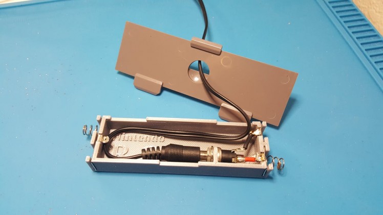
But before R.O.B. was ready to stream for hours on end, I had to do something about the battery situation; remember, R.O.B. runs on 4 AA batteries. I had also decided to tap into R.O.B.'s power pack, to supply power to the Notecard and ESP32, so sticking with AA's was out of the question. Instead, I decided to head over to tinkercad.com and design a battery replacement insert, that would allow me to replace the batteries for a wall adapter. I took my resulting 3D print, harvested some battery terminal contacts from my kids old broken toys, and I had R.O.B. running on wall power!
However, I did run into one limitation, and that is the fact that wall adapters are no replacement for batteries where current (I) is concerned. Between R.O.B.'s motors and the GPRS modem, my 6V/2A wall adapter was not responsive enough when quick, high-demand for current was required. As a workaround, I had to connect R.O.B. to my bench top power supply, so it could meet his power needs.
If you know of a high-performance wall adapter, please share in the comments.
1 / 2 • R.O.B. battery tray insert

R.O.B. battery tray insert
With a little help from my friends (a.k.a. my friends did it all for me), R.O.B. has a website that gives you an NES controller, which has been configured to operate R.O.B. exactly as he was programmed to behave in the Gyromite Test Direct screen.
1 / 2
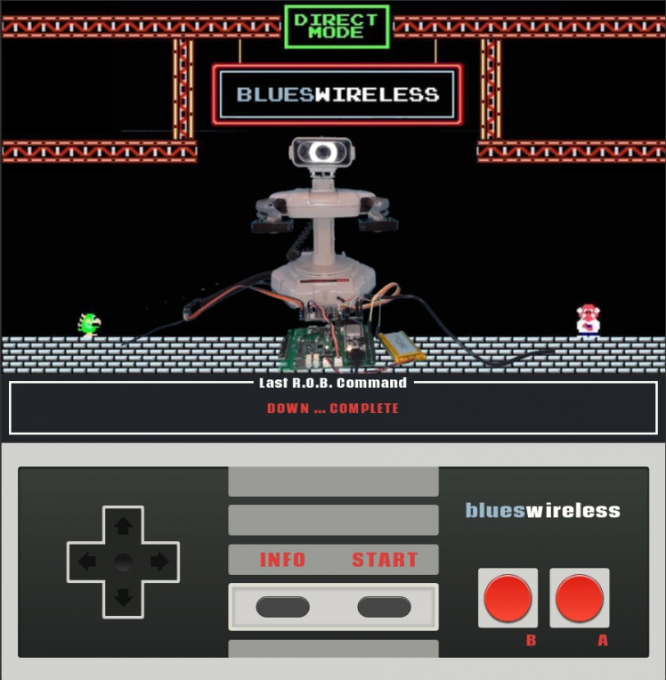

R.O.B. Controls
Come on over to http://nesrob.live and join the fun. I would love for you to experience this project first hand and take control of R.O.B.!
Leave your feedback...