
Campanion

Made by Louis-2020 / 3D Printing / Displays / Environmental Sensing / Lights / Sensors
About the project
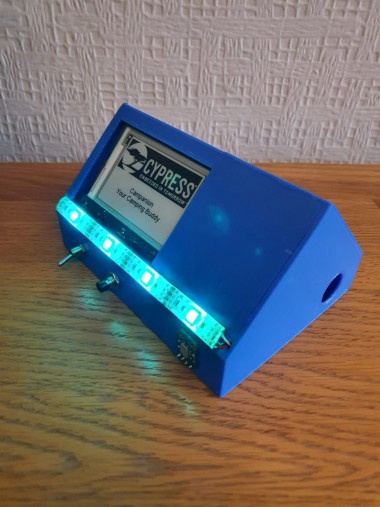
The Campanion is a useful device for camping trips/trips away . It has a carbon monoxide sensor, temperature readout, secret space for keys etc, night light, timer, and suggests activities. This is encased in a tent-shaped 3d printed case.
Project info
Difficulty: Moderate
Platforms: Adafruit, Autodesk, Cypress
Estimated time: 4 hours
License: GNU General Public License, version 3 or later (GPL3+)
Items used in this project
Hardware components


View all
Hand tools and fabrication machines
Story
Introduction
The Campanion is a device which has many functions;
It can detect carbon monoxide or gas levels and if they are too high a buzzer will be turned on creating a long sustained note.
The Campanion shows the temperature on its display
There is a secret space where you can store your keys etc
There is a function on the display to suggest camping related activities, eg go for a walk or cook a boiled egg
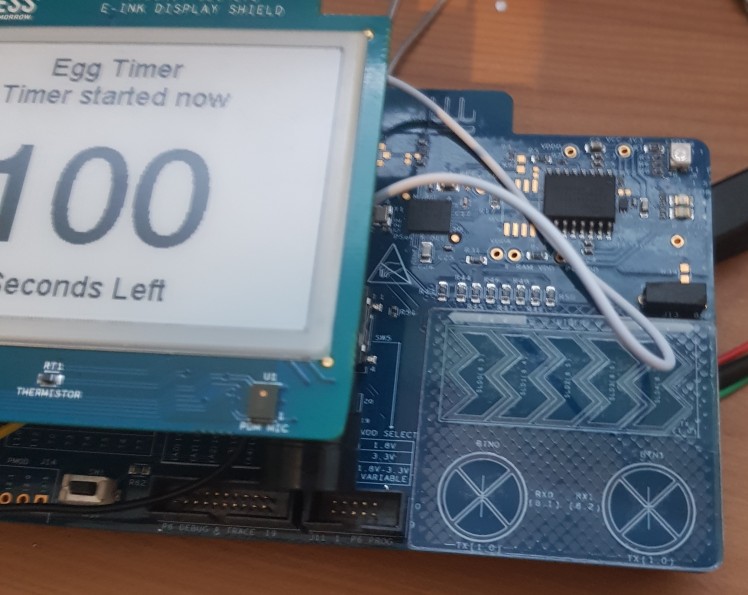
It has a timer, for example for cooking boiled eggs. The timer buzzer is different to the carbon monoxide buzzer, the timer buzzer beeps on and off rather than a continuous note. If the night light is on when the timer goes off the light pulses.
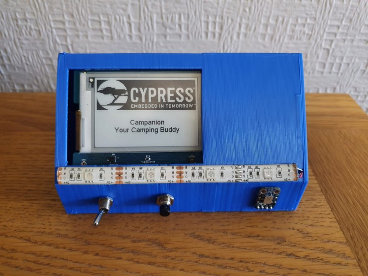
It has a night light, which also lights up the screen. The light is a mixture of blue and green. This can be turned on and off using the toggle switch on the front.
The Campanion is powered by an onboard battery which is just a regular battery bank. Therefore it does not always require mains electricity. The battery will last a long time even though it is small because the Campanion uses very little electricity. For example the e-ink display only uses power when it refreshes meaning that it will last as long as your camping trip. This is all encased in a fun custom 3d printed tent-shaped case that I designed.
Software
- To get started you need to install the modustoolbox from this link and PSoC creator from this link, I have used both of these in the development of my design, I started in modus toolbox, this is where I completed most of my project and then moved to PSoC creator. This is because I found that this PSoC 101 video tutorial covered what I wanted to do with the board exactly. This was useful because I was having difficulty getting the gas sensor working as an analog input and the video helped me work out how to use the analog to digital converter. This project could easily be used to created in Modustoolbox with minimal changes necessary.
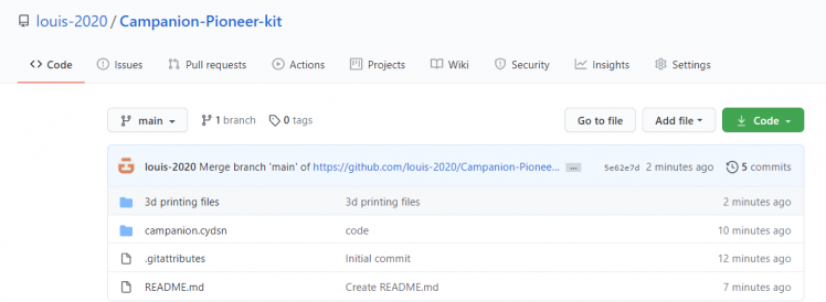
- Once the software is installed you can download the project code from my github, to do this you can download it as a zip by pressing the green code button and then download as zip. You can also clone the repository but I found it easier to download it as a zip as I am on windows.
- You now need to extract this project if you downloaded this as a zip, the easiest way to do this is to use windows file explorer.
- You can now open this is PSoC creator, this can be done by going to file, open, project/workspace then you can find the prok.cyprj and open it, this is the project file.
- Now is the time for you to edit the code if you want, you should be able to understand what the code does easily with the help of my comments.
- Before you program the kit you need to make sure that the switches on the board have not changed from the default settings which are SW5 - middle, SW6 - left and SW7 left also, by setting the switches to these values you are setting the board up for programming.
- You can now program your pioneer kit, once you have plugged the board into your computer using the supplied USB C cable. To program it you need to go to the debug menu at the top and press program, this will display a window which should show two options, I usually press the top option, these menus are the two cores of the board and it doesn't matter which one you pick. When you press ok on the board PSoC creator will automatically build the project and flash it to the board, this process could take a few minutes depending on the speed of your computer.
- If you are not seeing any devices showing up you should make sure that the switches are in the right position and that the USB cable is fully plugged in.
- If programming was successful the display should show the cypress logo and then 'Campanion your camping buddy'. Now you have completed your first step into creating the project.
3D Printing
It is now time for 3d printing, I printed this enclosure on my Da Vinci Jr 1.0 Pro 3d printer but this would work on any 3d printer as I will provide the STL files for you to slice in your own 3d printer slicer.
The settings I used are as follows:
0.4mm Nozzle Diameter
0.3mm Layer Height
Supports on
10% infill density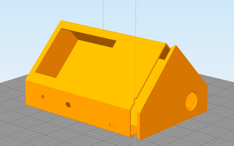
This design will require around 35 meters of filament and in total it took my printer around 9 hours to print but this could easily be reduced by using a larger nozzle and a larger layer height
I have provided the fusion 360 files which I used to create this with so if you want you can easily download fusion 360 for free from here and then edit enclosure if you want to add something like another sensor.
The right side should press onto the main enclosure with a little bit of force and should not come off easily.
Assembly
Now that you have 3d printed the enclosure and have the necessary components available, it is time to assemble the project, all this requires is some basic soldering knowledge
I assembled everything according to the diagram below, there is also a link to a google slide document for a clearer version of the picture
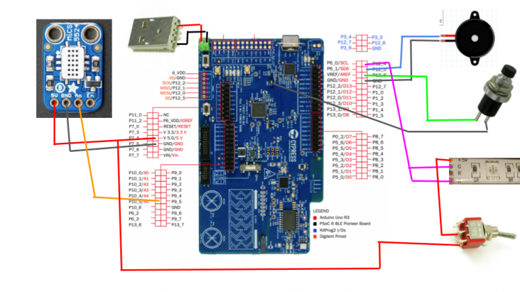
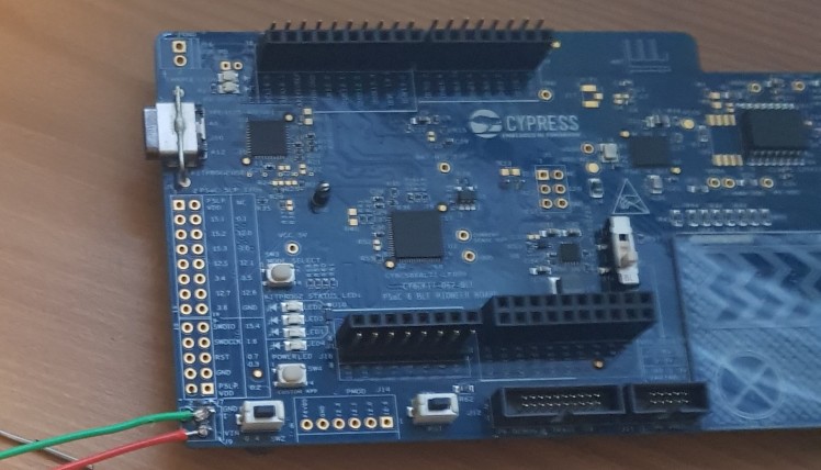
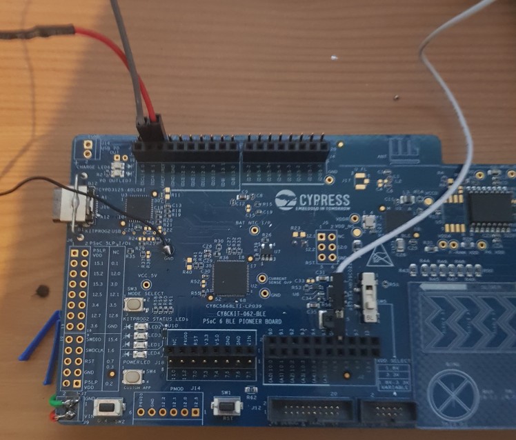
- I started by desoldering the terminal plug in the top left on the board, as my enclosure I designed has a snug fit so the board will not move around once inside, this will prevent unwanted noise and reduce the risk of damage to the components. This terminal plug gets in the way of the toggle switch and stops the board from sliding the entire way into the enclosure. By doing this you will need to solder directly to the pads on the board but you will not lose any power, it may just be a bit more difficult to change the power source. You could avoid this if you added some more clearance between the board and the sides of the enclosure but this would also meant that the fit would be looser.
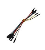
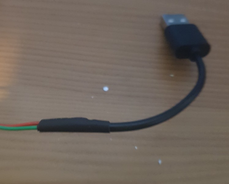
- Now it is time to make the connections to the USB cable which I got from an old micro USB cable I had laying around. On the picture above the positive wire is the bottom one which I conveniently used a red wire to represent. This will be soldered to the +5v wire on the USB port. My USB cable is coloured the conventional way with red as 5v and black as GND but I have seen many cables using an unconventional colouring system such as white for 5v so in this case it would be good to use a multimeter and check the connections using the continuity mode. I have also covered my connections in heat shrink to make them look nicer and to prevent any short circuits which would be bad, especially in this case when it is the power for the board.
- When you have done that you can set up the buzzer and the push button, I will start with the buzzer which will be used to tell you when the egg timer is up (beeping) and when a high level of gas is detected (long sustained tone). I have used one of the male to female jumper leads to connect the negative pin of the buzzer to ground, this specific GND pin is near P9 and I have had to bend the end of the lead 90 degrees to allow the jumper lead to stay clear of the e-ink display which will be placed over the top. Now for the push button, with this one It doesn't matter which pin of the button goes where, I have soldered some of the thin wire to the two pins of the button and then one of them to the female end of a jumper lead and the other to the GND post in the centre of the board.
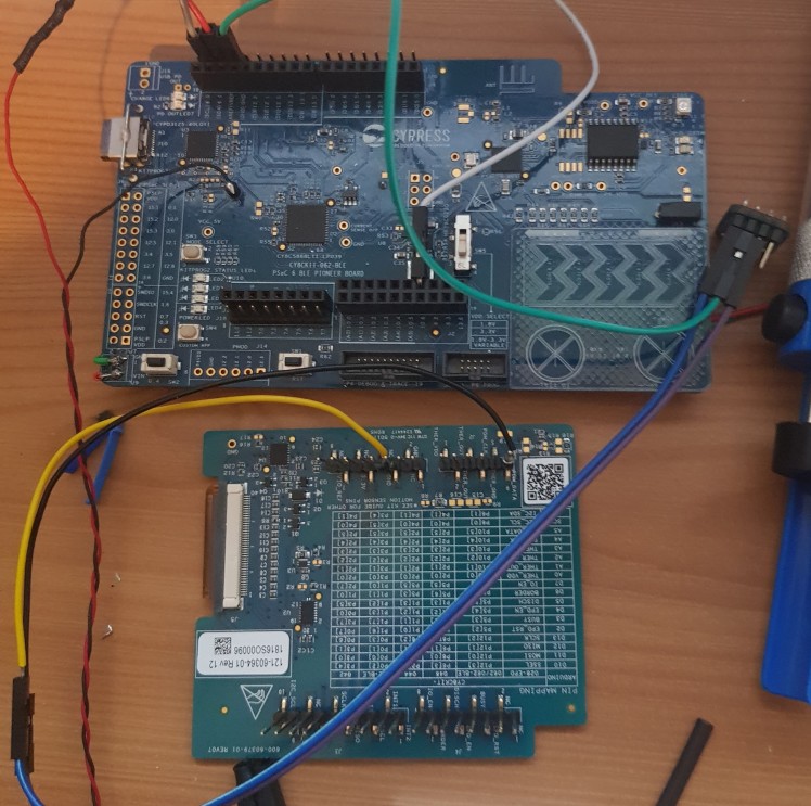
- Now that the buzzer and switch are wired up we can go on and wire up the 5v and analog 5 pins, these are a bit more difficult as these pins are already occupied with pins from the e-ink hat, before I go any further I have to say that this is not the best thing to do because you could easily damage the e-ink display by adding too much heat from the soldering iron. I have also checked on the datasheet for this display and made sure that the display is not using any of the pins that I want. Even though the 5v pin is being used already the display used very little power so it can easily supply power to the display, sensor and a small string of LED strip lights. While you solder one wire to the +5v pin on the board and the other wire to the A5 pin you should aim to keep your soldering iron on the board for as little time as possible, this will bring down the chances of you damaging the display through heat.

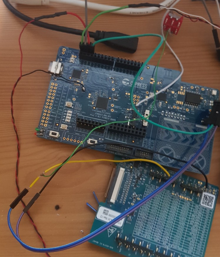
- Now you can wire up the LED strip, I do not have a conventional LED strip, I am using a common anode LED strip, this means that instead of applying 5v to each colour you want on the LED strip, you bring the colour that you want's pin down to ground, and all the other time you have it set to high. To turn the colour LEDs on you need to have 5v to ground. I have only used the +5v, G and B pads on the LED strip, this is because the red on the LED strip seems to overpower the other colours and I want to create a warm light effect which is achieved very well using just green and blue mixed together.

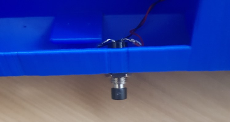
- It is now time to wire up the gas sensor, this will always be detecting the gas levels in the room that this is placed in and when the levels go past a certain threshold the buzzer will play a long sustained note. Even though this gas sensor can not detect which type of gas it is detecting, it still works as a excellent safety feature because if there is any gas in your tent, you don't want to be there. To wire up the sensor you use 3 female to female jumper leads, the first one is for the ground pin on the sensor which is the middle pin for me to the GND on the board next to the push button connection. The next one is 5v on the sensor which is connected to the wire that was soldered onto the display which I used a yellow wire for, the third one is for the analog 5 which is from the AO pin on the sensor to the other wire that I soldered to the display which is P10_5, also known as analog 5.
- Now we can wire up the LED strip this will be using a toggle switch so that we can turn the LED strip on when we want and off when we want. This switch will be wired on the 5v wire coming from the LED strip. To wire it you need to solder the wire coming from the LED strip to the middle pin on the toggle switch and then solder another wire coming from on of the sides of the toggle switch. The side you choose to the other wire to come from will be the side that when the toggle switch is switched to that side the current can pass through, in our case lighting the LED strip up.
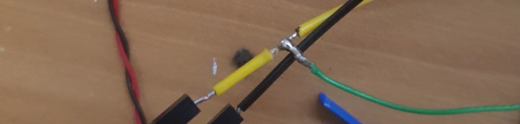
- To wire the LED strips +5v wire to main 5v wire which is shared by the display, gas sensor and now the LED strip we need to do some fancy wire stripping, this looks more complex than it is. All you need to do is strip the wire once more, leaving about a centimetre of insulation. Then you need to pull the bit of insulation off and trim it down a little bit. This will leave a gap for you to solder the extra wire to. You can see how the joint looks up close in the picuture below. To make this extra safe you could add some electrical tape to prevent future shorts. It might be difficult to make this look nice but it is worth it if it stops your board from breaking.
- It is now time to slide the board into the 3d printed enclosure but before you get too carried away you need to first put the push button through the hole in the middle on the enclosure. You will also need to bend both the pins outwards on the button to stop them from interfering with the boards as it slides into the enclosure. Then you should put some electrical tape over the exposed connectors to prevent any shorts. This button should then be secured in place with the nut it came with.
- Before you slide the board you also need to route the wires for the gas sensor through the rectangular hole to the right of the enclosure. I have also tucked the buzzer under the display because there is enough space and it is plenty loud enough inside the enclosure. When you are going to slide the board into the enclosure you also need to slide the toggle switch in first as it is going to need to be secured in place.
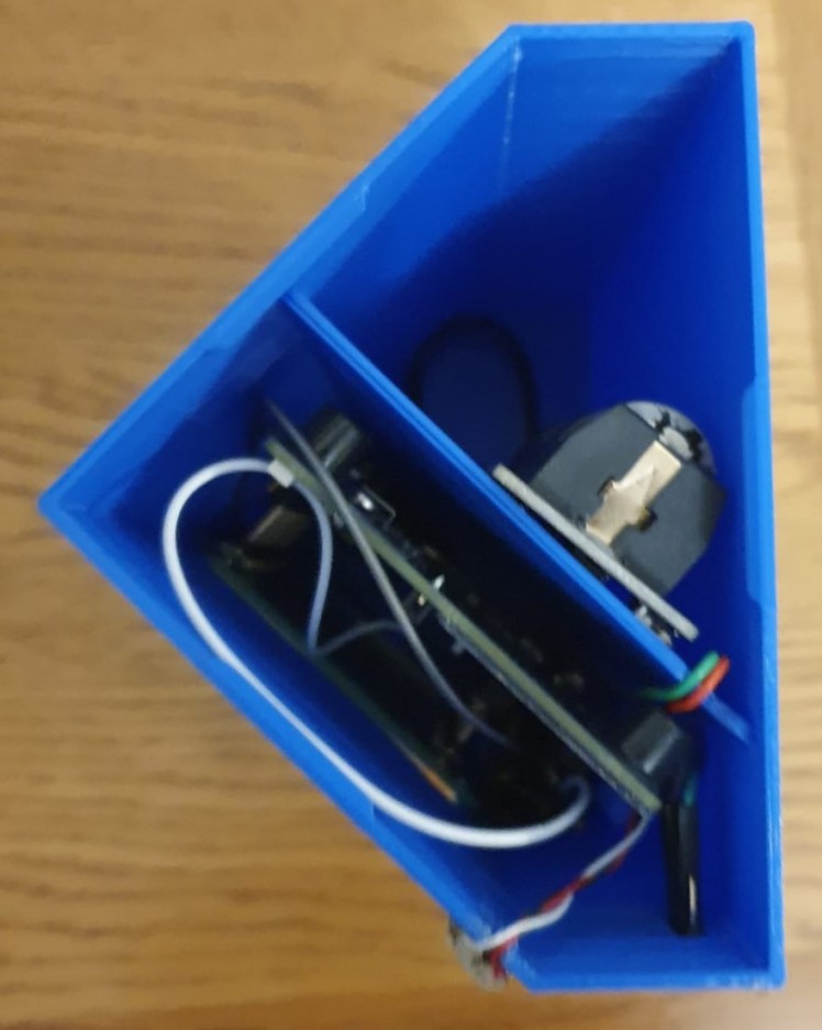
- Now you can slowly slide the board into the enclosure, it should be a tight fit so it will require some force to get all the way in. When you are about half way done you should push the toggle switch through the hole to the left on the enclosure and then use the included nut to secure it in place before adding some electrical tape to prevent any shorts. Now you can route the wires for the LED strip through the groove and then stick it in place using the included double sided sticky tape. I also used some of my own tape to make the bond stronger as previously I have found that the included tape is not strong enough to stick to 3d printed parts well. I have also included a groove which is where the power cables can go to the top is not obstructed. For my battery bank I have used and 18650 to USB converter board, this includes all the safety features and is a small power bank. This will last a long time because the Campanion does not use much power and it only uses it when the display updates.
- To secure the gas sensor onto the enclosure I used a dab of hot glue, you shouldn't use much as if you do it will be difficult to the sensor off again and a small amount of hot glue holds the sensor in place well anyway. After following these steps, you should be left with a fully complete Campanion, this is how mine looks.
Videos
This video is showing the campanion in action, I have purposely set the gas sensor threshold very low to demonstrate the buzzer. I would simulate the presents of gas to test it but I cannot do this safely. This sensor is from a reputable brand so I trust that it works well.
This video is of me demonstrating the large space behined the board which you can store keys and other important things in.
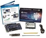
I have chosen the PSoC 6 BLE pioneer kit for this project because it contains a e-ink display which means that little power is used and the battery will last for the entirety of your camping trip or just your trip away
Schematics, diagrams and documents
CAD, enclosures and custom parts
Code
Credits
Related products


Leave your feedback...