
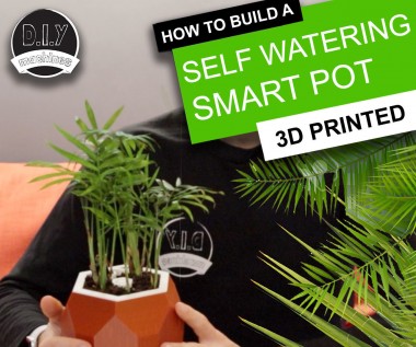
Automatic Smart Plant Pot - 3d Printable

Made by DIY-Machines / 3D Printing / Garden / Home Automation / Plants / Sensors
About the project
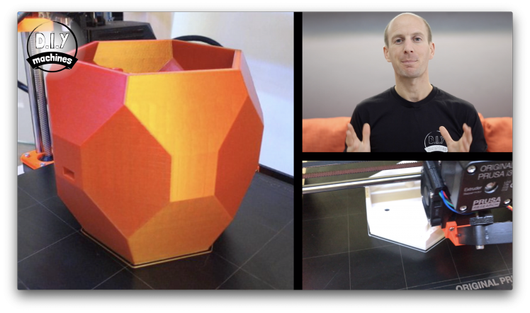
Sometimes when we go away from home for a few days or are really busy the house plants (unfairly) suffer. This is my solution a Smart Plant Pot which includes integrated water tank, soil moisture sensor, water level sensor, pump and status LED all controlled by an Arduino Nano.
Items used in this project
Hardware components

View all
Story
Step 1: Video Tutorial
If you prefer videos to reading then please check out the video above. Otherwise keep on reading and I'll step you through creating your own Smart Plant Pot one step at a time.
Step 2: Things You'll Need
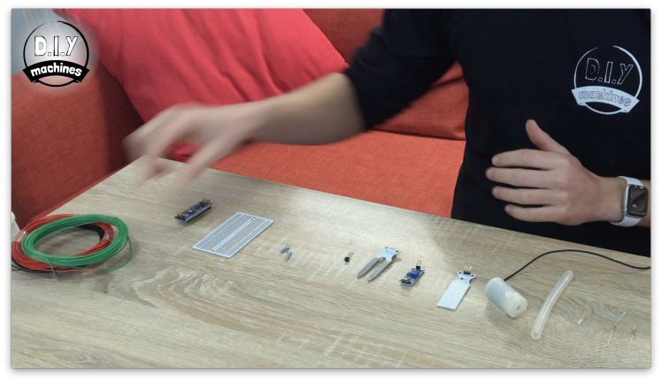
You are going to need a few things to build one of your own. Here is a list of the items along with links to where you can find them on Amazon.
- Arduino Nano: https://geni.us/ArduinoNanoV3 x1
- Mini submersible pump: https://geni.us/MiniPump x1
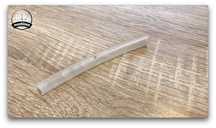
- 5mm tubing: https://geni.us/5mmTubing 5cm worth
- Transistor: https://geni.us/2npn2222 1x 2N2222
- Resistors (1k and 4.7k): https://geni.us/Ufa2s One of each
- Wire: https://geni.us/22AWGWire for connecting components together
- 3mm LED: https://geni.us/LEDs x1
- Water level sensor: https://geni.us/WaterLevelSensor x1
- Bolts: http://geni.us/NutsAndBolts M3 x 10mm x2
- Soil moisture sensor: https://geni.us/MoistureSensor x1
- Half Perma-proto board: https://geni.us/HalfPermaProto x1
- PLA Filament: https://geni.us/PLAFilament
Step 3: Print the 3D Printable Parts
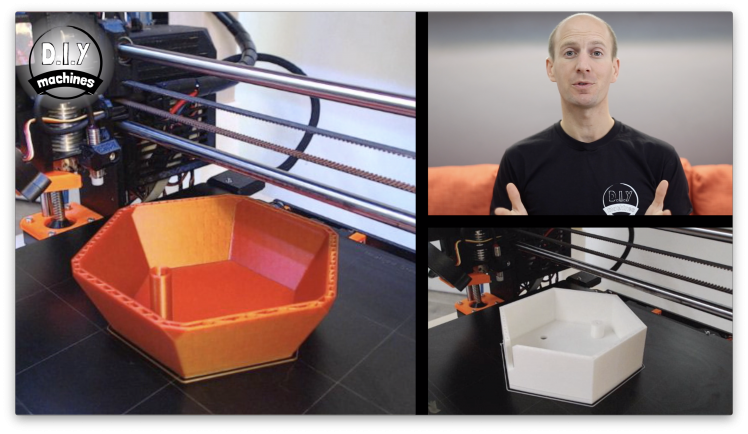
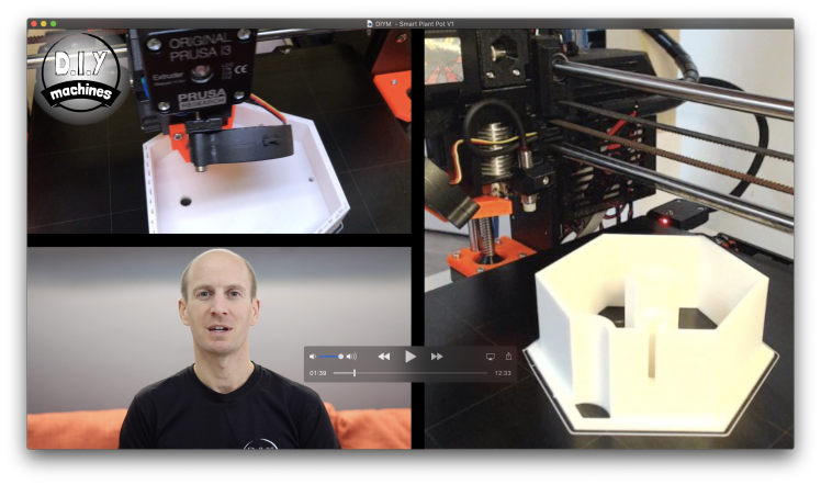
The 3D printed parts will take some time to print so it's a good place to start them while you are waiting for anything you've ordered to arrive.
You'll find the CAD files available to download here: https://www.thingiverse.com/thing:3537287
I printed all mine in PLA at a layer height of 0.15mm. I printed the 'outer pot' with three perimeters and this ensured that it was water tight for me. Check your print is watertight before using it to ensure you don't risk damaging any of your electronic components. If it fails you can try any of the following:
- Print it with more perimeters/walls
- Increase the flow rate of the extruder
- Treat the inside of the print with some kind of sealer
Step 4: Prepare the Electronics & Circuit Diagram
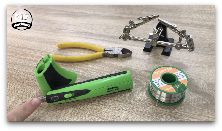
We can turn our attention to the electronics. You will need a few tools to help you assemble and solder the various electronic components for this project:
- Solder wire
- Soldering iron (I'm using this cool battery powered one I recently got: https://geni.us/SealeySolderingIron )
- Wire clippers
- Helping hands
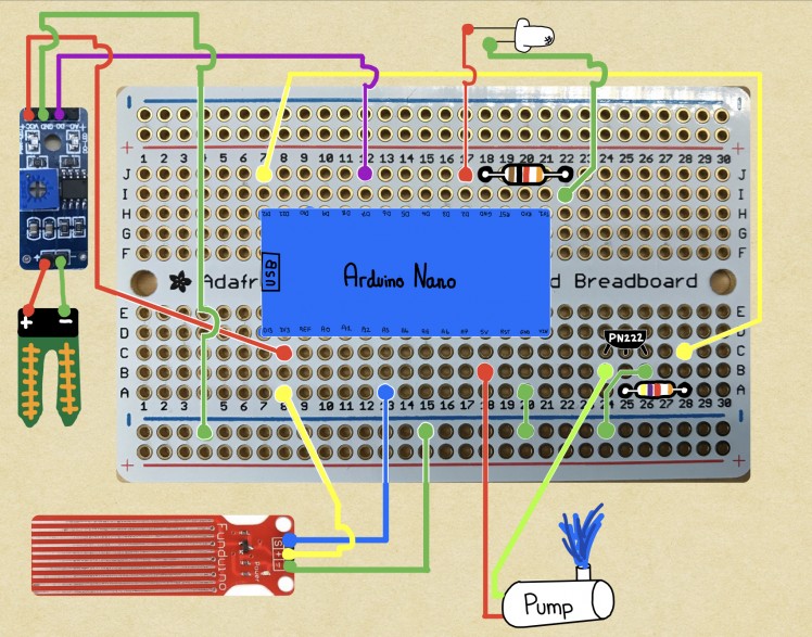
Attached is a soldering diagram. If you prefer you can skip the following sections and follow the diagram yourself, though if you prefer I'll step you through it component by component now.
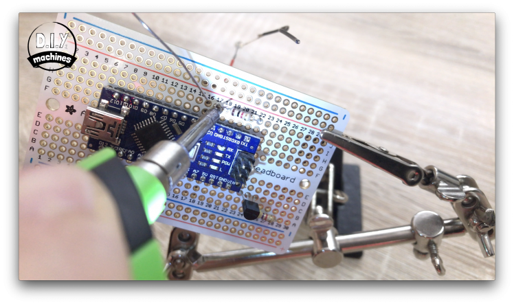
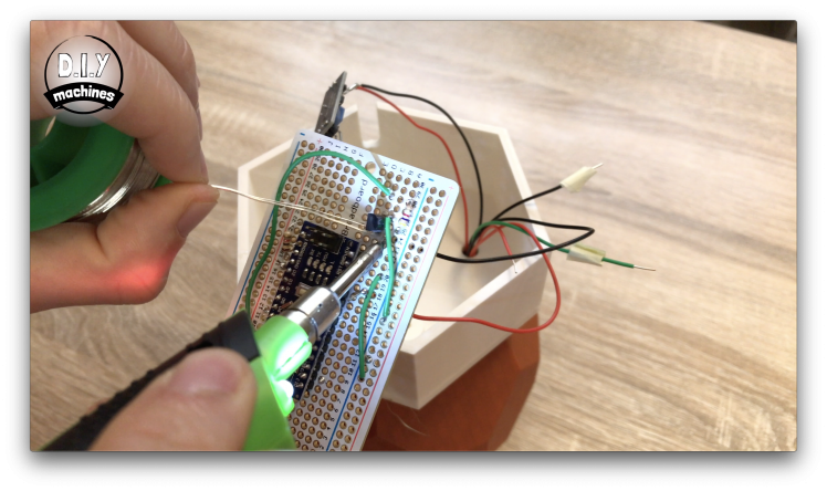
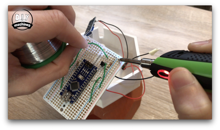
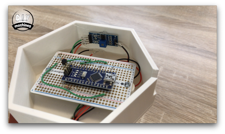
Step 5: Solder Arduino to Proto Board
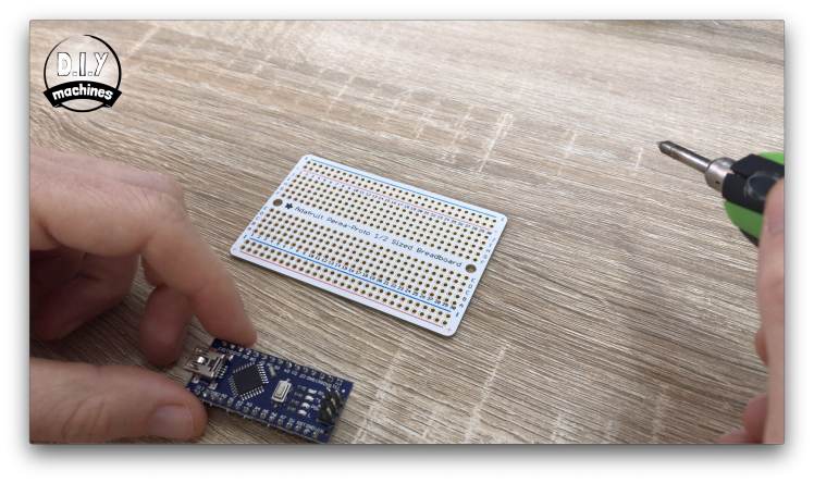

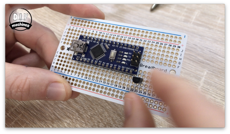
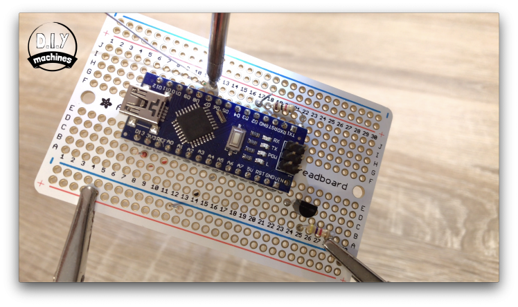
First we will solder the Arduino Nano to our Perma-Prota board. As we go though I will refer to the holes on the Perma-Prota board by their co-ordinates such as hole B7. The letters and numbers for the holes are written along the edges of the Perma-Proto board.
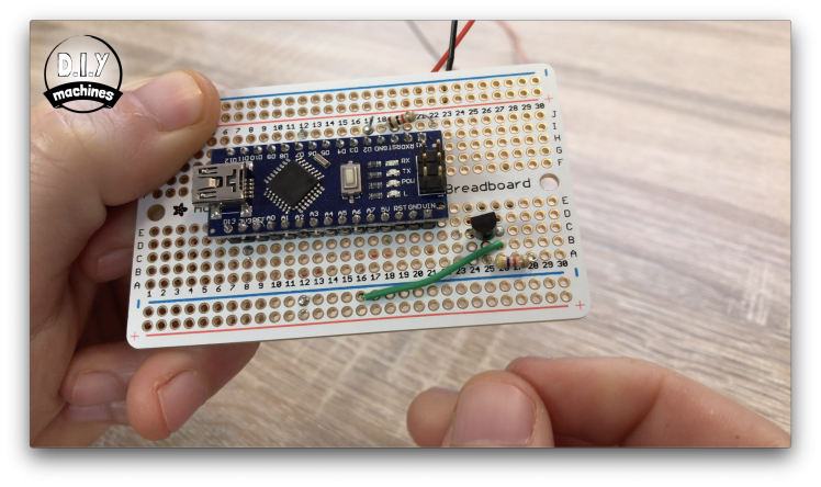
To position the Arduino Nano in the correct place put pin D12 on the Arduino though hole H7 on the prototype board. Then turn over the board and solder the pins in place.
Step 6: Add the Transistor and Resistors
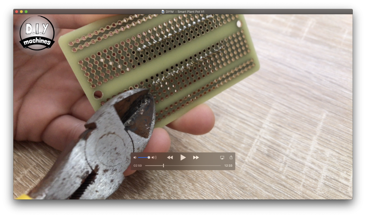
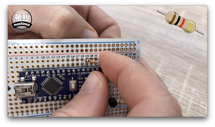
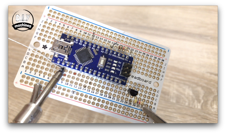
The three legs of the transistor want to pass through the holes C24, 25 and 26 on the board. The flat face of the transistor wants to be facing towards the centre of the board. Once you have soldered this in place trim the excess lengths of leg from the other side with the wire cutters.
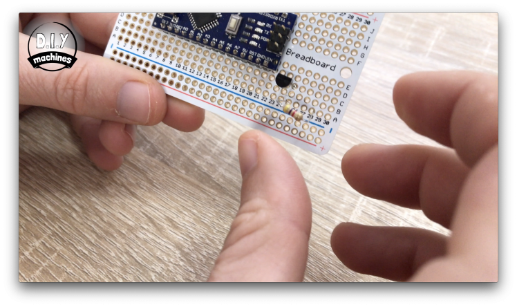
The 4.7 k ohm resistor (the colour bands go yellow, purple then red) goes through holes A25 and A28.
The 1k ohm resistor (brown, black then red bands) goes through holes J18 and J22.
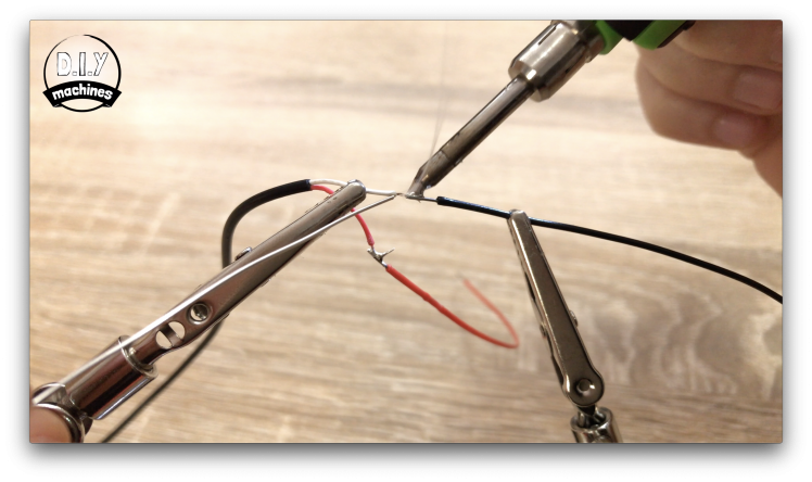
Step 7: Prepare the LED and Connect to Board.
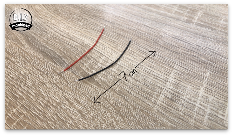
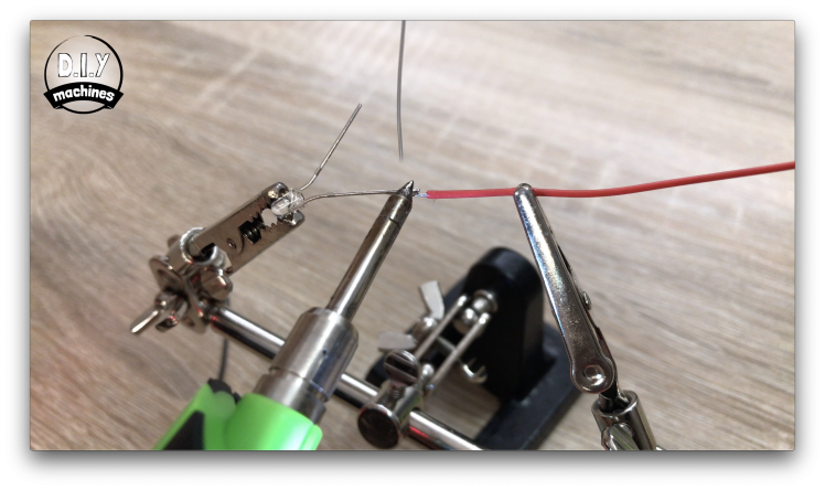
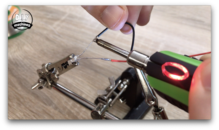
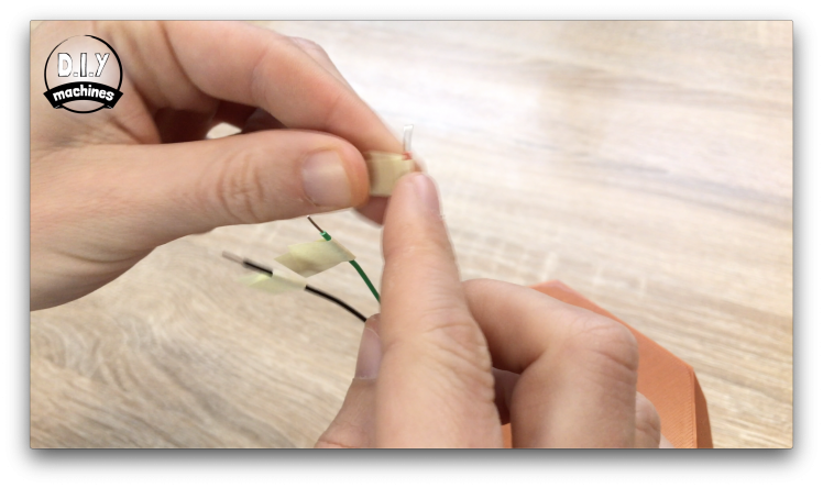
Solder a separate 7cm long wire to each of the LEDs legs. Once you have done this use some insulation tape or heat shrink to prevent the two legs and wires from making contact and shorting our circuit later.
Now the positive leg from the LED, that's the longer of the two legs, needs to be soldered to hole J17 on the board. The negative is then soldered to hole I22.
Step 8: Prepare the Pump
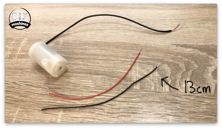
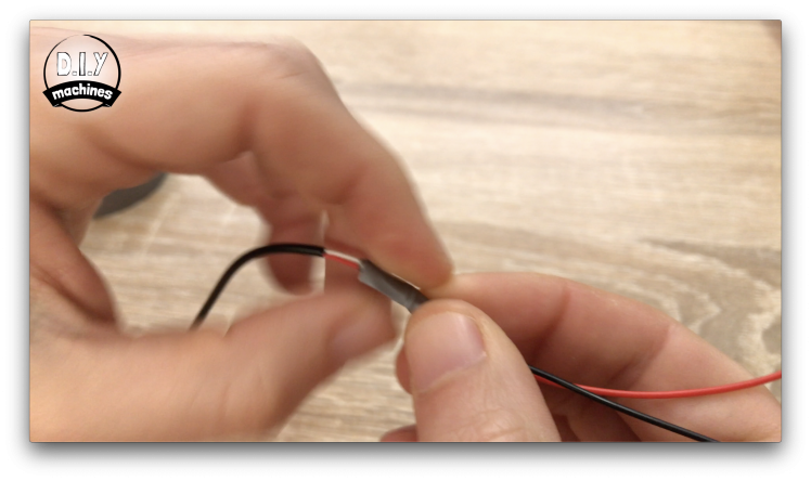
Before we install and connect the pump we need to extend its wires. Add an additional 13cm onto both of the wires coming from the water pump. Again, add some insulation tape to the connections after you have soldered them together.
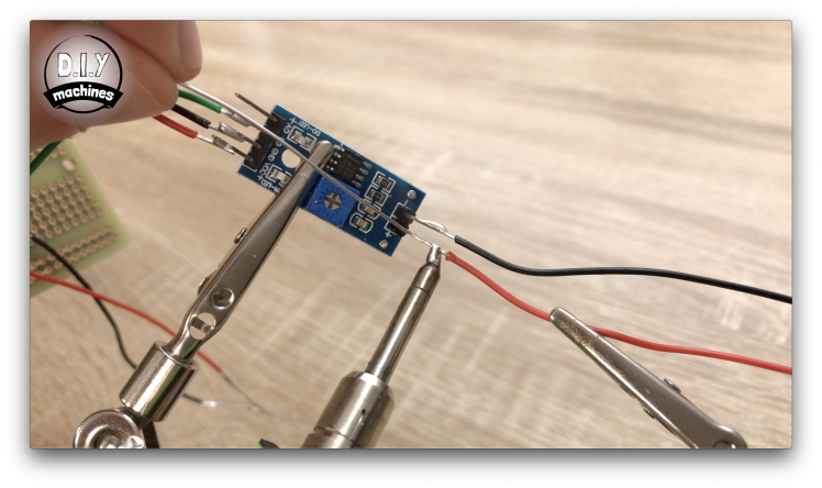
Step 9: Prepare Water Level Sensor

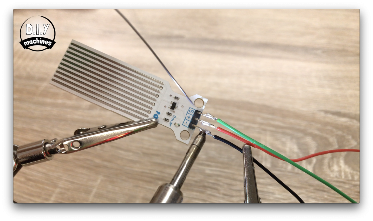
This time solder three 20cm wires to the three pins of the water level sensor.
Step 10: Connect Moisture Sensing Components Together

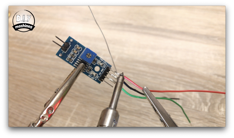
Attach a 10cm to the following pins on the moisture sensors module:
- D0
- GND
- VCC
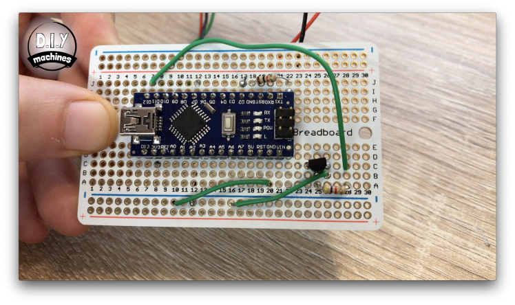
Then solder the wire from D0 to J12 on the Proto board, the ground wire to anywhere along the ground rail and finally the wire from VCC to hole C8.
Next solder two 25cm wires to the negative and positive pins on the other side of the sensors module.
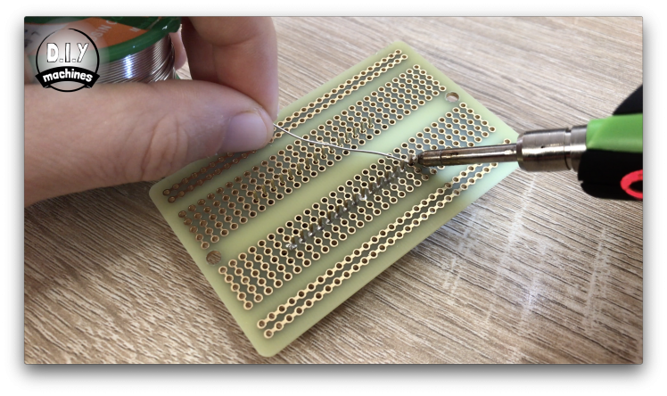
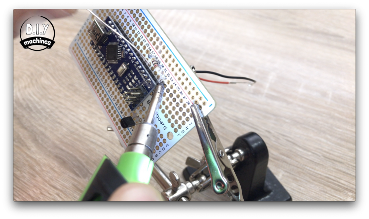
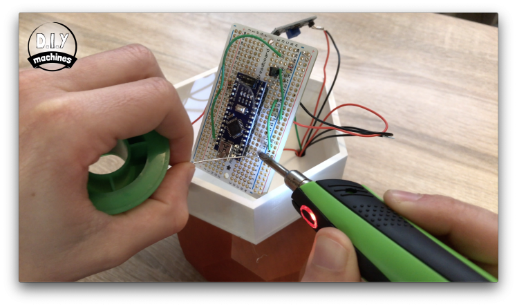
Step 11: Add Additional Connections to the Proto Board
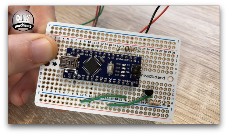
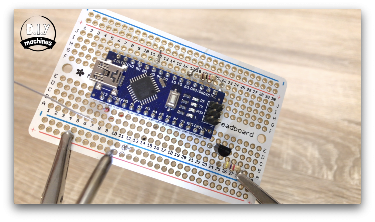
Use a short length of wire (green in the photos) to connect holes B26 to the ground rail and then another wire to connect our ground rail to the ground pin of the Arduino via hole A20.
We need one more wire to connect holes C28 and J7.
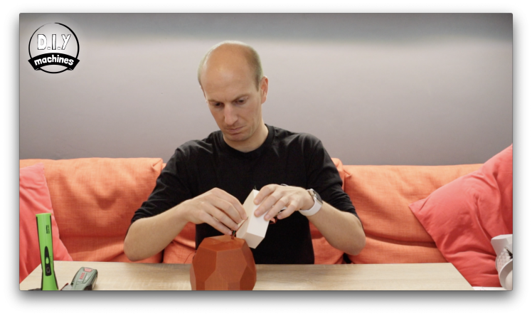
Step 12: Let's Start Assembling Our Parts
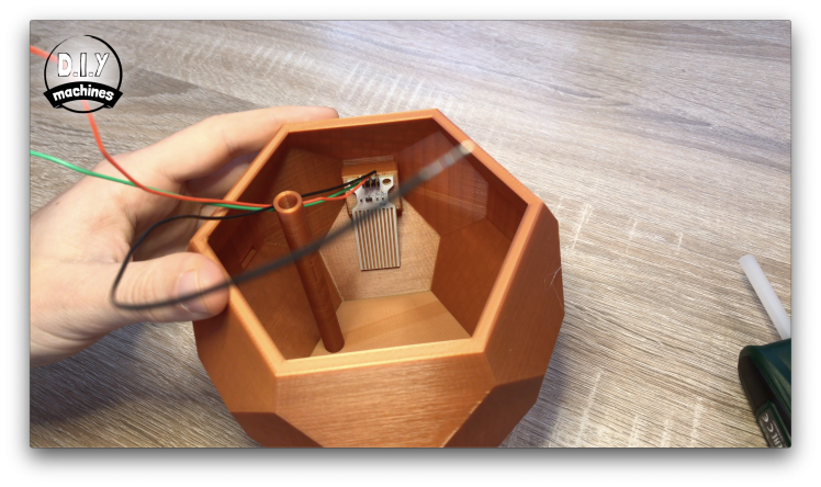
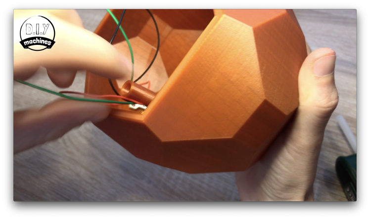
Use some hot melt glue or similar to fix the water level sensor onto its fixing plate on the inside of the Outer Pot. Ensure that the top of the sensor is inline with the top of mounting plate.
Now feed the three wires from this sensor down through the hole you'll find in the side of the column that rises up from the bottom of the Outer Pot. When they appear out the bottom you can pull them through. Now is also a great time to label them whilst we are certain of what they are connected to.
Whilst we have our glue to hand we should fix the LED into place by pushing it though its hole in the stand and gluing it there.
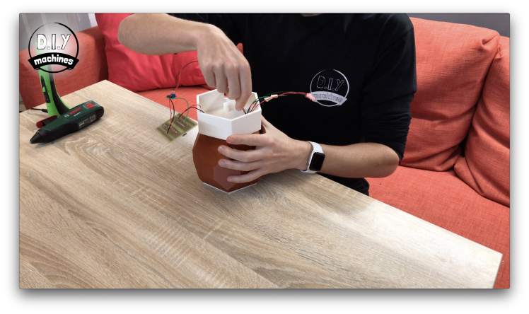
Step 13: Assemble the Water Pump
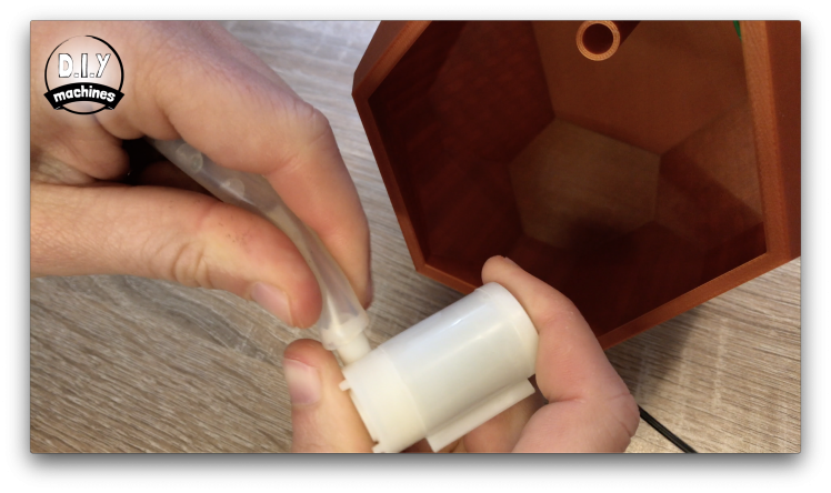

We can also thread the wires from our water pump through the same hole in the Outer Pot as we did for the water level sensor and then label the wires when they come out the other side.
Now take the 5cm of rubber tubing, attach it to the water pump and then the other end to underside of the Inner Pot.
We can then carefully slide the Inner Pot down into the Outer Pot. There is a thin slot for the wires to pass through, be careful that you don't catch the wires when assembling these two parts.
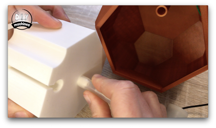
Step 14: Add the Stand

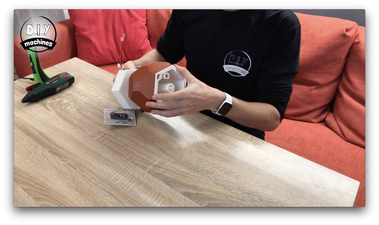
Now we can thread all our labeled wires through the hole in the stand and then place it all on our worktop upside down. Use some hot melt glue to fix the pot onto the stand and keep it in a central position.
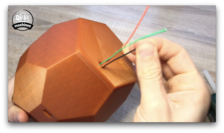
Next take the two wires coming from our moisture sensor and thread these down through the whole that runs all the way through our Smart Plant Pot in the other direction. These should pop out through the top of the column now instead of the small side hole we were utilising earlier.
Step 15: Some More Soldering
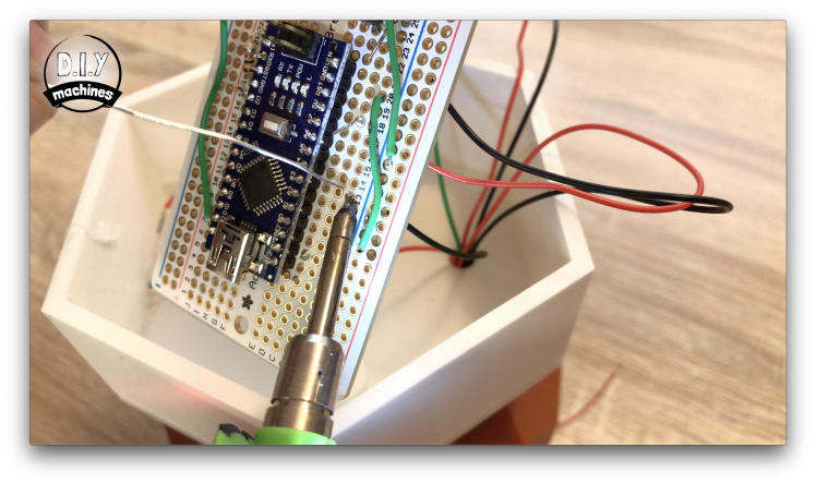
Now solder the wires from the water pump to holes B18 and B24.
The ground wire from the water sensor can be connected to anywhere along the ground rail. The positive lead is soldered to hole A8 and the sensor wire is connected to A13.
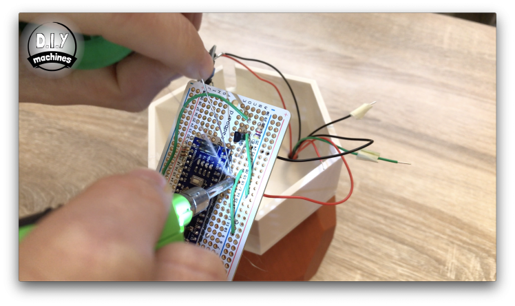
Step 16: Cable Management
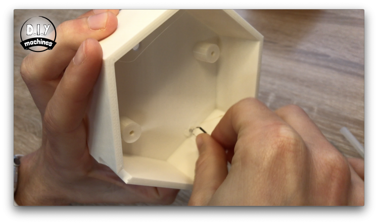
Now glue the module for the soil moisture sensor to one of the interior wall of the stand as shown in the photo.
Using the two bolts we can wriggle the remaining wires into a more tidy arrangement underneath the board and then bolt it in place. Ensure that the end of the Arduino with the USB connection is facing the hole in the stand for the USB cable to be able to pass through.
Step 17: Pot Up a Plant!

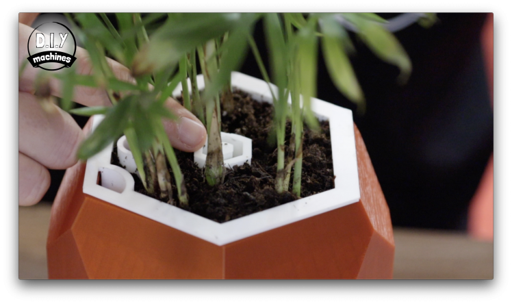
Now we can add our plant. :)
You can be as creative as you want with your choice of plant and growing medium. Just be sure to keep the water outlet, inlet and wiring hole clear of any growing medium.
You can also decorate the top with something like small colourful gravel if you wanted to.
Step 18: Connect Moisture Sensor
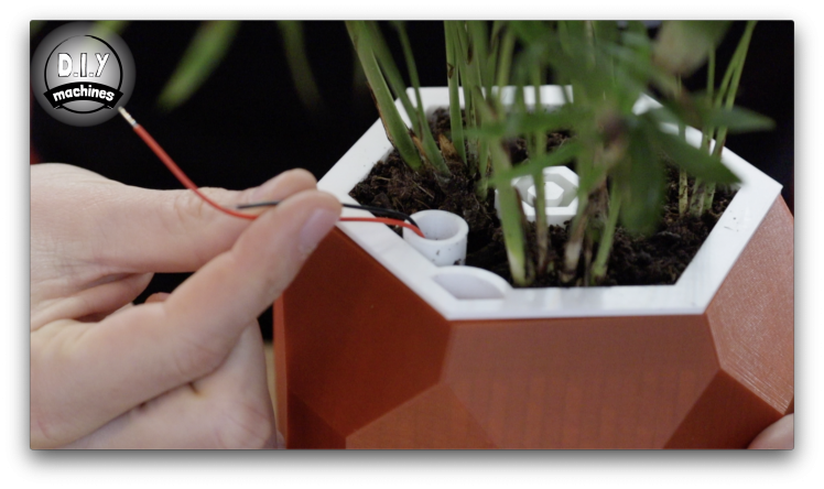


Now we can connect the moisture sensor to the two wires coming out the top of the plant pot then insert its prongs into the soil.
Any excess wire can be pushed back down into the plant pot.
Step 19: Upload Code

You will find the code for the project here: https://github.com/DIY-Machines/SmartPlantV1
Once you have downloaded it, open the file 'SmartPlant-V1-1.ino' in the Arduino IDE and upload it to your creation. With everything going well you should see and hear the following happen:
- When the upload is complete and the Arduino restarts the LED should flash quickly five times to confirm the code is running.
- The IDE serial monitor will print the current water level reading.
- After a few more second you should hear the pump start up as we have not yet calibrated the values for the soil moisture sensor.
- The LED should then begin to blink slowly to warn us that there is not any water in the internal tank.
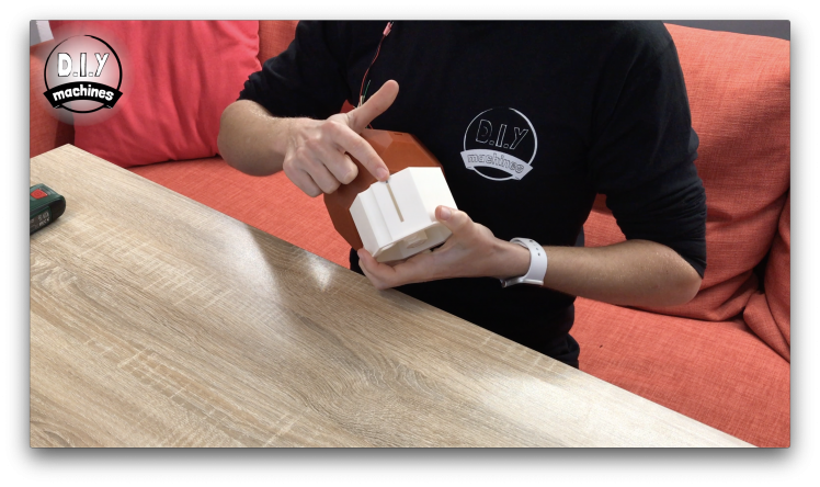
Step 20: Calibrate Soil Moisture Level
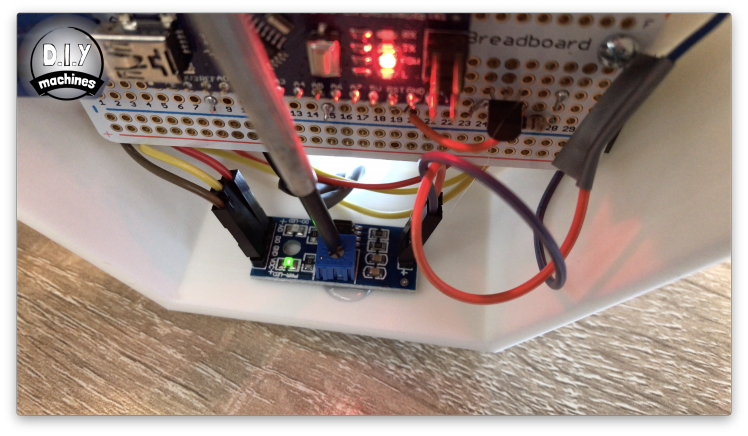
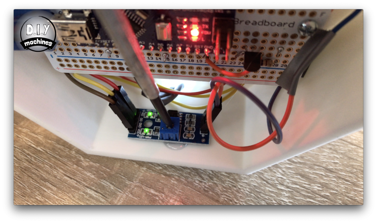
On the underside of the pot is where we attached the sensor module for the soil moisture sensor. This module has a potentiometer on it which we will use to set the level it will flag to the Arduino as the soil being moist enough. To do this, check the dampness of the soil for the plant is just at the bare minimum you would be happy with. Wait an hour or so for the moisture to even itself out through the growing medium and around the sensor.
We can then use a small screwdriver to turn the potentiometer until the second light on it switches on, at this point stop and then turn it back the over direction until the light just goes off. This is then set correctly.
If you ever need to adjust the moisture level of the soil, this is where you do it.
Step 21: Calibrate the Water Level in the Reservoir
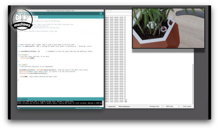
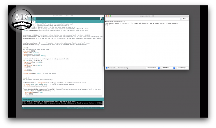
This time open the code 'Water_Tank_Threshold_Test.ino' in the IDE and upload it. We will use this for a short while to help set the correct threshold level for the water level sensor.
Once uploaded open the serial monitor and slowly begin adding water to the tank until you start to see a reading from the sensor. Stop at this point and wait until the readings become fairly consistant. Note down the average value it is now displaying.
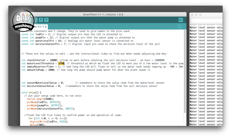
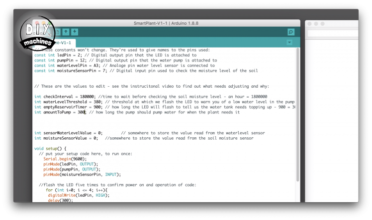
Now we can re-upload the main code and head to the variables at the top to update a few values. First we will enter the value we just noted into the variable 'WaterLevelThreshold'.
Whilst we are here we can also set the check interval value to 180,000. this means the moisture level of the soil will be checked every hour. The 'emptyReservoirTimer' value wants to be set to 900. This means the LED will flash slowly for 30 mins to let us know we need some more water in the tank before the code continues to check the plant, water it if we have any water left and then go back to trying to get our attention.
The variable for the 'amountToPump' controls how much water is pumped to the plant when we water it. I've set mine to 300 but you can adjust this if you need more or less water.
Step 22: Just Add Water..
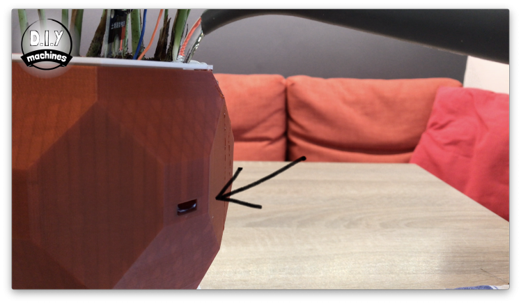
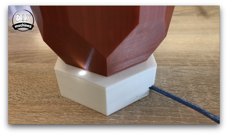
Now we can fill up the water reservoir. Keep an eye on the overflow hole shown in the image. When you see water here stop filling the pot. This is here to ensure you don't flood the internal electronics.
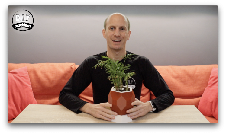
Step 23: Finished!
And that's it - Smart Plant Pot complete. :)
I hope you have enjoyed building yours. Please consider sharing your make on Thingiverse, I really enjoy seeing them: https://www.thingiverse.com/thing:3537287
Support me on Patreon: https://www.patreon.com/diymachines
SUBSCRIBE:www.youtube.com/c/diymachines
If you would like to say thanks please also consider buying me a coffee: https://ko-fi.com/diymachines
Schematics, diagrams and documents
CAD, enclosures and custom parts
Code
Credits
Related products


Leave your feedback...