
Arduino Temperature Alarm Led Display Flash And Beep

About the project
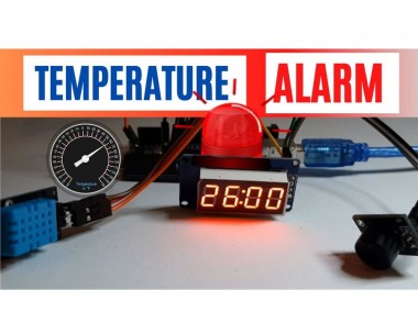
Temperature Alarm that will beep and flash when the temperature is out of out of boundaries. Watch the Video!
Project info
Difficulty: Easy
Estimated time: 1 hour
License: GNU General Public License, version 3 or later (GPL3+)
Items used in this project
Hardware components

Story
In this tutorial we will measure the temperature and when it is out of boundaries the LED display will start to Flash and the buzzer will beep. Once the temperature is back within the boundaries flashing and beeping will stop.
Watch the video!
You can Download the Project File below.
Also check out my other tutorials on how to use TM1637 LED Display
https://www.instructables.com/Arduino-Display-Time-on-TM1637-LED-Display-Using-R/
https://www.instructables.com/Arduino-Counter-Using-TM1637-LED-Display-Obstacle-/
https://www.instructables.com/Arduino-Display-Temperature-on-TM1637-LED-Display/
https://www.instructables.com/Arduino-Counter-Using-TM1637-LED-Display/
Step 1: What You Will Need
1 / 5

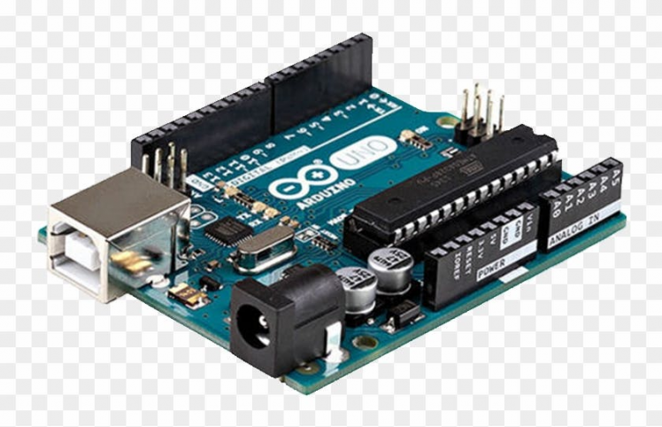
- Arduino UNO (or any other Arduino)
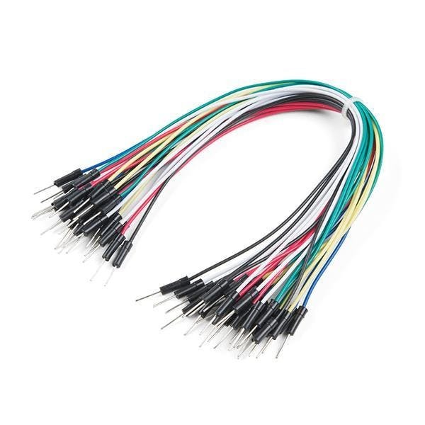
- Jumper wires
- LED Display TM1637
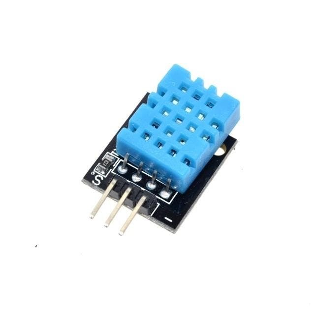
- DHT11 Temperature & Humidity sensor (or any other type of temperature sensor)
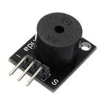
- Buzzer module
- Visuino program: Download Visuino
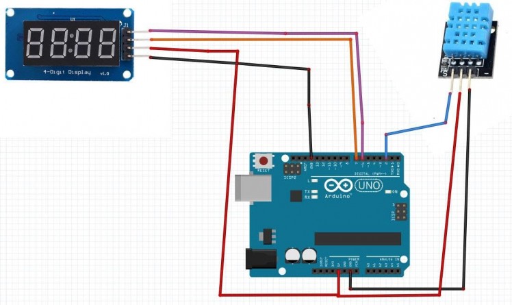
- Connect LED Display pin[CLK] to Arduino digital pin[6]
- Connect LED Display pin[DI0] to Arduino digital pin[7]
- Connect LED Display pin[GND] to Arduino pin[GND]
- Connect LED Display pin[VCC] to Arduino pin[5V]
- Connect DHT11 Sensor pin [VCC] to Arduino pin [5v]
- Connect DHT11 Sensor pin [GND] to Arduino pin [GND]
- Connect DHT11 Sensor pin [S] to Arduino Digital pin [2]
- Connect Buzzer pin [+] to Arduino pin [5V]
- Connect Buzzer pin [-] to Arduino pin [GND]
- Connect Buzzer pin [S] to Arduino digital pin [8]
1 / 2
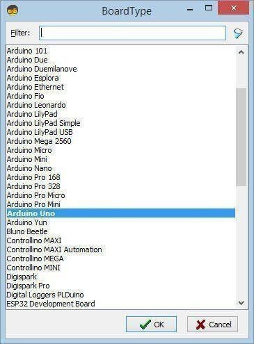
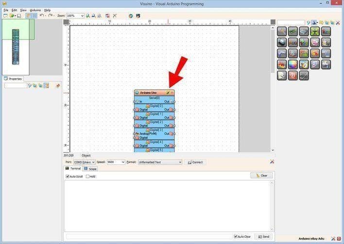
The Visuino: https://www.visuino.eu needs to be installed. Start Visuino as shown in the first picture Click on the "Tools" button on the Arduino component (Picture 1) in Visuino When the dialog appears, select "Arduino UNO" as shown on Picture 2
Step 4: In Visuino Add Components
1 / 7

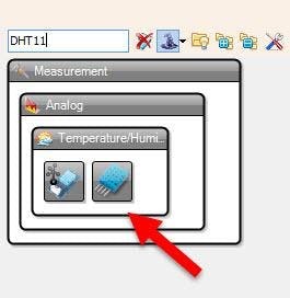
- Add "DHT11" component
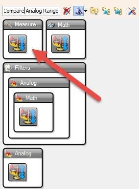
- Add "Compare Analog Range" component
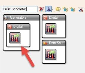
- Add "Pulse Generator" component
- Add "Delay" component
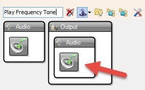
- Add "Play Frequency Tone" component
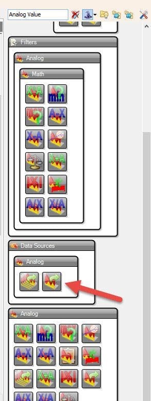
- Add "Analog Value" component
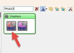
- Add "TM1637 7 Segment Display 4 Digits Module + 2 Vertical Points (CATALEX)" component
1 / 11

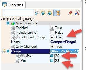
- For this example we will use the Temperature range 23C & 26C, but you can adjust the temperatures to your needs.
- Select "CompareRange1" and in the properties window set "Is Outside Range" to True
This means that we want to measure & to trigger the alarm if its more than 26C or less than 23C, If you want to trigger the alarm just in the range betwen 23-26C then set the "Is Outside Range" to False
- Select "CompareRange1" and in the properties window set Range > Max to 26
- Select "CompareRange1" and in the properties window set Range > Min to 23
This means: that the Alarm will be triggered if the temperature is below 23 or above 26
Optional: You can also set "Include Limits" to true, this means that the alarm will also be triggered by 23C & 26C
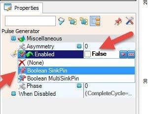
- Select "PulseGenerator1" and in the properties window set "Enabled" to false, and click on the Pin Icon and select "Boolean SinkPin"
- Select "PulseGenerator1" and in the properties window set "When Disabled" > "Reset" to true
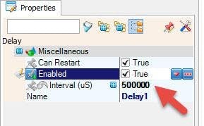
- Select "Delay1" and in the properties window set "Interval (uS)" to 500000
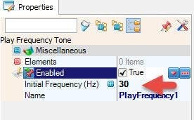
- Select "PlayFrequency1" and in the properties window set "Initial Frequency (Hz)" to 30
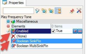
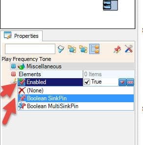
- Select "PlayFrequency1" and in the properties window select "Enabled" & click on the Pin Icon and select "Boolean SinkPin"
- Select "AnalogValue1" and in the properties window set "Value" to 0.5
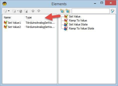
- Double click on the "AnalogValue1" and in the "Elements" window drag 2x "Set Value" to the left side
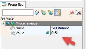
- Select "Set Value2" and in the properties window set "Value" to 0.5
- Close the "Elements" window
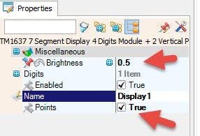
- Select "Display1" and in the properties window set "Brightness" to 0.5 and click on the Pin Icon and select "Float SinkPin" and also set "Points" to True
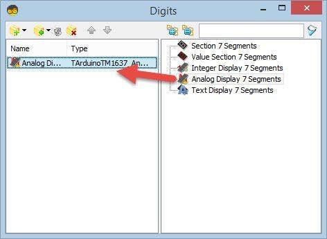
- Double click on the "Display1" and in the "Digits" window drag "Analog Display 7 Segments" to the left side
- Close the "Digits" window
1 / 3
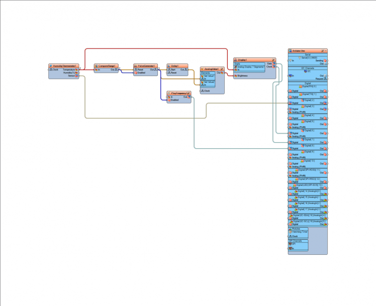
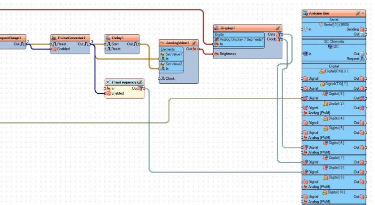
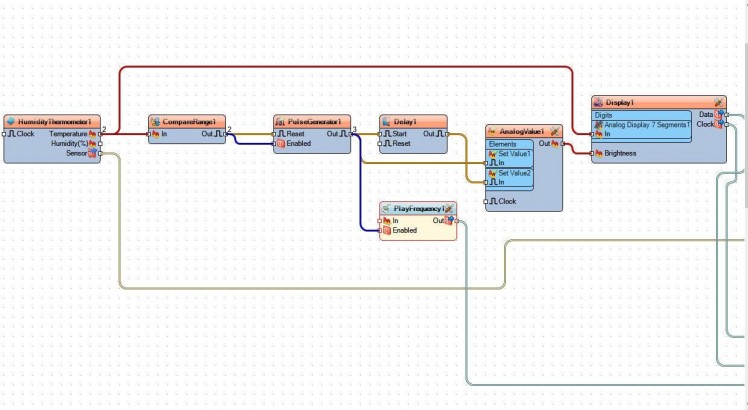
- Connect "HumidityThermometer1" pin [Sensor] to Arduino board digital pin[2]
- Connect "HumidityThermometer1" pin [Temperature] to "Display1" > "Analog Display 7 Segments1" pin[In]
- Connect "HumidityThermometer1" pin [Temperature] to "CompareRange1" pin[In]
- Connect "CompareRange1" pin[Out] to "PulseGenerator1" pin [Reset] and pin [Enabled]
- Connect "PulseGenerator1" pin[Out] to "Delay1" pin [Start], to "AnalogValue1" > "Set Value1" pin[In] and to "PlayFrequency1" pin [Enabled]
- Connect "Delay1" pin[Out] to "AnalogValue1" > "Set Value2" pin[In]
- Connect "AnalogValue1" pin [Out] to "Display1" pin [Brightness]
- Connect "PlayFrequency1" pin [Out] to Arduino board digital pin[8]
- Connect "Display1" pin [Data] to Arduino board digital pin[7]
- Connect "Display1" pin [Clock] to Arduino board digital pin[6]
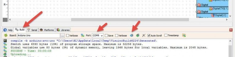
In Visuino, at the bottom click on the "Build" Tab, make sure the correct port is selected, then click on the "Compile/Build and Upload" button.
Step 8: PlayIf you power the Arduino modules, the LED Display will show the current temperature, once the temperature goes outside of the boundaries the LED Display will start to flash and the piezo buzzer will beep.
Congratulations! You have completed your project with Visuino. Also attached are the Visuino project files for Master and Slave, that I created for this Tutorial, you can download it and open it in Visuino: https://www.visuino.eu
Schematics, diagrams and documents
Code
Credits
Related products


Leave your feedback...