
Arduino Nano And Visuino: Control Stepper Motor With Buttons

Made by Ron / Displays / Home Automation / Robotics / Sensors
About the project
Connect stepper motor to Arduino, and control it with buttons - Quick and Easy!
Project info
Difficulty: Easy
Platforms: Arduino, SparkFun, Visuino
Estimated time: 1 hour
License: GNU General Public License, version 3 or later (GPL3+)
Items used in this project
Hardware components

Software apps and online services
Story
Stepper motors are often used in Arduino projects, whenever something needs to be moved or turned. In this Tutorial, I will show you how easy it is to connect Stepper Motor to Arduino Nano and control it with Buttons.
Step 1: Components
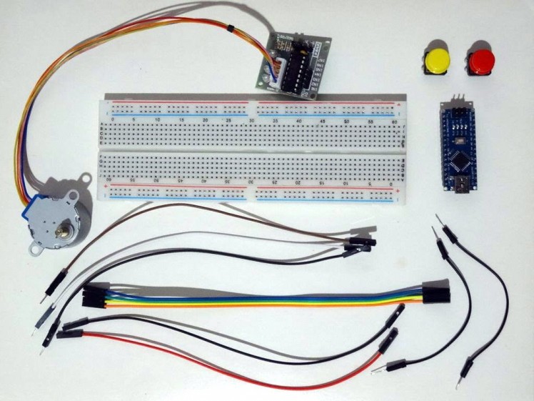
- One Arduino compatible board (I use Arduino Nano, because I have one, but any other will be just fine)
- One 5V Stepper Motor with Driver Board (I used 28BYJ-48 stepper with ULN2003 driver board)
- One Breadboard
- 6 Female-Female jumper wires
- 3 Male-Female jumper wires
- 2 short Male-Male jumper wires
1 / 5 • Picture 1

Picture 1

Picture 2

Picture 3

Picture 4

Picture 5
- If not already connected, plug the Stepper Motor connector into the Driver Board
- Connect one end of Female-Female jumper wires(Blue, Green, Yellow and Orange wires) to the IN1 to IN4pins of the Stepper Driver(Picture 1)
- Connect Ground(Black wire), and Power(Red wire), to the Stepper Driver module (Picture 2)
- Connect the other end of the Power wire(Red wire) to the 5V power pin of the Arduino board(Picture 3)
- Connect the other end of the Ground wire(Black wire) to Ground pin of the Arduino board(Picture 3)
- Connect the IN1 wire(Blue wire) to the Digital pin 4 of the Arduino board(Picture 4)
- Connect the IN2 wire(Green wire) to the Digital pin 5 of the Arduino board(Picture 4)
- Connect the IN3 wire(Yellow wire) to the Digital pin 6 of the Arduino board(Picture 4)
- Connect the IN4 wire(Orange wire) to the Digital pin 7 of the Arduino board(Picture 4)
- Picture 5 shows where are the Ground, 5V Power, and Digital 4 to Digital 7 pins of the Arduino Nano
1 / 2 • Picture 1

Picture 1

Picture 2
To start programming the Arduino, you will need to have the Arduino IDE installed from here: http://www.arduino.cc/ .
The Visuino: https://www.visuino.com also needs to be installed.
- Start Visuino as shown in the first picture
- Click on the "Tools" button on the Arduino component (Picture 1) in Visuino
- When the dialog appears, select Arduino Nano as shown in Picture 2
1 / 3 • Picture 1

Picture 1

Picture 2

Picture 3
- Type "step" in the Filter box of the Component Toolbox then select the "4 Wire Stepper Motor" component (Picture 1), and drop it in the design area
- Click in the "Out" box containing the pins of the Stepper component to start connecting all the Out pins at once (Picture 2)
- Move the mouse over the "Digital" input pin of the "Digital[ 4 ]" channel of the Arduino component. The Visuino will automatically spread the wires so they will connect correctly to the rest of the pins(Picture 2)
- Optionally you can specify the Speed of the Stepper, by setting the value of the StepsPerSecond property of the Stepper4Wire1 component (Picture 3)
1 / 2 • Picture 1

Picture 1

Picture 2
- In Visuino, Press F9 or click on the button shown on Picture 1 to generate the Arduino code, and open the Arduino IDE
- In the Arduino IDE, click on the Upload button, to compile and upload the code (Picture 2)
1 / 2 • Picture 1

Picture 1

Picture 2
Picture 1 shows the connected and powered up stepper motor. If everything is properly connected, the motor should start rotating. On Picture 2 you can see the complete Visuino diagram.
Step 7: Connect the Buttons to Arduino
1 / 6 • Picture 1

Picture 1

Picture 2

Picture 3

Picture 4

Picture 5

Picture 6
- Place the 2 buttons on the Breadboard(Picture 1)
- Connect the Male end of one of the Male-Female wires(White wire) to one end of one of the buttons(Picture 1)
- Connect the Male end of another one of the Male-Female wires(Brown wire) to one end of one of the second button (Picture 1)
- Connect one of the short Male-Male jumper wires(Black wire) between the unconnected end of one of the buttons and the Ground Bus of the Breadboard(Pictures 2 and 3)
- Connect the other one of the short Male-Male jumper wires(Black wire) between the unconnected end of the second button and the Ground bus of the Breadboard(Pictures 2 and 3)
- Connect Male end of the last Male-Female wire(Black wire) to the Ground bus of the Breadboard(Picture 4)
- Connect the other end of the Ground wire(Black wire) to the Ground pin of the Arduino (Picture 5)
- Connect the other end of the Second Button wire(Brown wire) to the Digital pin 2 of the Arduino board(Picture 5)
- Connect the other end of the First Button wire(While wire) to the Digital pin 3 of the Arduino board(Picture 5)
- Picture 4 shows in Red the Arduino Nano pins that ware connected in this step
1 / 4 • Picture 1

Picture 1

Picture 2

Picture 3

Picture 4
When connecting buttons to Arduino, we don't need resistors, as the digital pins of Arduino, have optional Pull-Up resistors. I already made a tutorial on how to use Arduino Pull-Up resistor, and I will use the same here:
- Select the Arduino component(Picture 1)
- In the Object Inspector expand the "Digital" property, then the Digital[ 2 ] sub property, and set the value of the IsPullUp sub property to True(Picture 1)
- In the Object Inspector expand the Digital[ 3 ] sub property, and set the value of the IsPullUp sub property to True(Picture 1)
When using Pull-Up resistors, the the values of the buttons are inverted - when the button is pressed, the value is False, instead of True. To correct this, we need to add Inverters in the code:
- Type "inv" in the Filter box of the Component Toolbox then select the "Boolean Inverter" component (Picture 2), and drop two of them in the design area
- Connect the "Out" pin of the "Digital[ 2 ]" channel of the Arduino component to the "In" pin of the Inverter1 component(Picture 3)
- Connect the "Out" pin of the "Digital[ 3 ]" channel of the Arduino component to the "In" pin of the Inverter2 component(Picture 4)
1 / 3 • Picture 1

Picture 1

Picture 2

Picture 3
- Type "or" in the Filter box of the Component Toolbox then select the "Boolean Or" component (Picture 1), and drop it in the design area
- Connect the "Out" pin of the Inverter1 component to the "Pin[ 0 ]" Input pin of the Or1 component(Picture 2)
- Connect the "Out" pin of the Inverter2 component to the "Pin[ 1 ]" Input pin of the Or1 component(Picture 3)
1 / 4 • Picture 1

Picture 1

Picture 2

Picture 3

Picture 4
- Select the Stepper component (Picture 1)
- In the Object Inspector click on the Pin button at front of the Enabled property, and select "Boolean SinkPin" (Picture 1)
- In the Object Inspector click on the Pin button at front of the Reversed property, and select "Boolean SinkPin" (Picture 2)
- Connect the "Out" pin of the Or1 component to the "Enabled" input pin of the Stepper component(Picture 3)
- Connect the "Out" pin of the Inverter1 component to the "Reversed" input pin of the Stepper component(Picture 4)
1 / 2 • Picture 1

Picture 1

Picture 2
- In Visuino, Press F9 or click on the button shown on Picture 1 to generate the Arduino code, and open the Arduino IDE
- In the Arduino IDE, click on the Upload button, to compile and upload the code (Picture 2)
1 / 2 • Picture 1

Picture 1

Picture 2
Congratulations! You have completed the project.
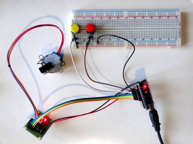
Picture 1 shows the connected and powered up project.
If you press one of the buttons, the stepper will start to rotate, until you release the button. If you press the other button the stepper will start rotating in opposite direction, until you release the button, as you can see in the Video.
On Picture 2 you can see the complete Visuino diagram.
Also attached is the Visuino project, that I created for this Tutorial. You can download and open it in Visuino: https://www.visuino.com
Credits
Related products


Leave your feedback...