
Arduino Lightsaber

Made by 314Reactor / Lights / Sensors / Star Wars / Wearables
About the project
A colour changing lightsaber based on Arduino technology.
Items used in this project
Hardware components


View all
Story
Key Goals
- Make a lightsaber that is relatively easy to wield.
- Have it make sounds on ignite/extuinguish/general use.
- Have the colour be customisable on the fly.
Never tell me the odds.
I’ve thought about making a lightsaber for some time – but I always wanted to make one that would actually cut through stuff; then I realised that would require some serious gear and smarts – like the geniuses over at the Hacksmith:
So eventually I thought well I may as well just make one that doesn’t cut through stuff but would have some additional functionality – such as being able to customise the blade colour on the fly. So I got to work.
These aren’t the droids you’re looking for.
Do. Or do not. There is no try.
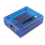
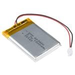
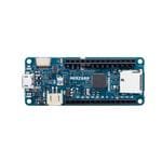
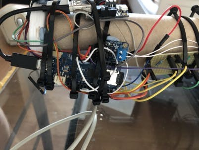
I chose the MKR ZERO as it has the ability to take LiPoly batteries and charge them directly as well as an inbuilt I2S DAC for outputting audio from an SD Card; perfect for this project.
It also has a good deal of pins, more than enough for the project. Unfortunately throughout testing I didn’t think about an off button, so by the time it came around to putting a LiPoly in it to power it I realised there is no in built on/off button (unless I totally missed it). So I opted to chuck a switched Powerboost 500c in with the LiPoly batt – you can find instructions on how to do this here.
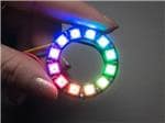
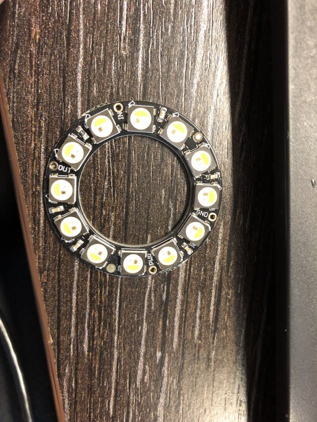
I also chose the Neopixel ring as it was a good size for the project and a decent brightness and would provide a good blade of fully-customisable colour.
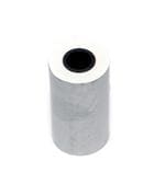
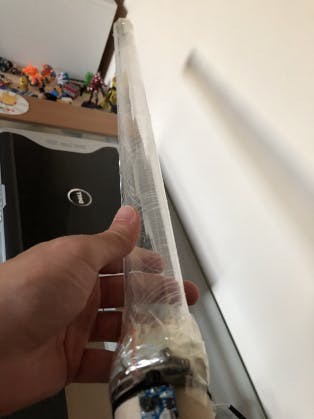
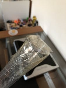
For the actual light producing core itself I had tried a cut down kitchen roll tube and taped the VR lens to the top – I chose this configuration because it would focus the colours of the Neopixels down to a more focused spot and hopefully be a more intense light beam – but in practice this did not turn out to work very well and it was better to just directly have the Neopixels shine through the PVC pipe – but feel free to try for yourself and see what happens (this is mentioned in the intro crawl, which I created before I realised this).
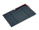
In terms of wiring up the gear first up is the Neopixel ring (pin connections should transpose from the Arduino used there over to the MKR ZERO), with the Power pin connecting to the +5v line from the battery box. I opted for a separate power supply for the Neopixels to ensure they got a good amount of amperage.
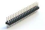
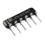
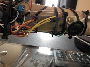
I hooked up some headers and things to a bit of veroboard in order to ensure that everything can share the same VCC/GND lines, as well as the 10k ohm resistors connecting to ground on the Arduino for the buttons that will be mentioned later on.
 IMG_5093
 IMG_5094
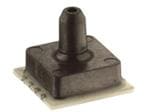
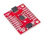
Next up the colour sensor needs wiring up – I also ran a line from the LED pin to D7 on the MKR ZERO so that the LED can be controlled by code so its not on all the time. The power from this is run from the 3v VCC/GND line on the Arduino itself.
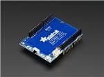
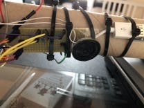
Now for the amplifier – you can follow the instructions here for a hookup to a custom made amp but the connections are similar for the one I’m using, the VIN connected to the 5v rail of the Arduino and GND > GND of course – the DAC0 pin on the MKR ZERO connects to the A+ pin and the A- pin goes to GND.
 IMG_5091
 IMG_5088
 IMG_5097
 IMG_5096
 IMG_5092
;
;
IMG_5092
;
;
 1 / 2 • IMG_5093
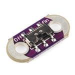
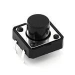
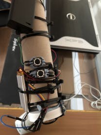
Finally, hook in the buttons for ignition/extinguish and colour sensing. I opted to go for the digital route and have each button running from the 3v on the Arduino and into digital pins 0 and 1. Also having the outputs ran to a 10k ohm resistor each, that runs to GND to keep the pins pulled LOW.
 IMG_5098
 IMG_5097
 IMG_5076
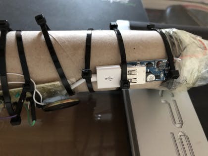
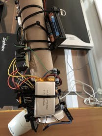
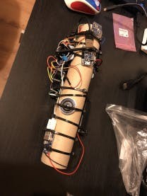
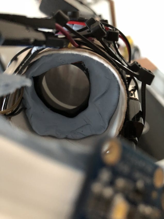
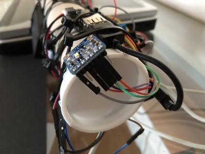
I then stuck the parts to the outside of the main kitchen roll and put the Neopixel ring inside the tube as you can see here:
For extra strength I put on a bunch of tie wraps to hold it all together as well.
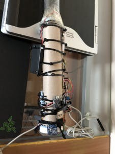
The final piece is the PVC pipe, I made sure it was attached firmly with -of course- blu tac, tape and tie wraps. As well as some reflective material onto the top of the blade and a cap on the bottom, to reduce light leak.
 IMG_5099
 IMG_5090
In terms of software the first thing to get working is the Neopixels themselves – Adafruit has a very good guide on this that has some code that can be used for testing.
Next up is getting the colour sensor to work and relay information Adafruit again saves the day here by having a guide with useful code.
Lastly is testing the audio for the ignition sounds – Arduino themselves have some code/setup for this for the MKR ZERO itself as well as a standard Arduino board.
I combined elements from all of the above code and added in some of my own in order to get all three working together nicely – one issue I found was with trying to get the saber to make a constant hum sound was difficult, as it would be looping the sound; in which during the buttons would not respond. So I had to cut the hum sound unfortunately – any ideas on this let me know.
For some reason when there wasn’t a sound initiated a horrendous buzz would be coming out of the speaker constantly. So I worked around this by playing a tiny silent wav file in setup(), which seemed to have resolved it – again, any ideas on this let me know; I may have goofed some wiring up somewhere.
You can grab the code and audio files here.
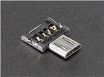
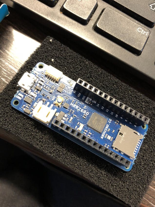
Chuck the wav files onto a FAT16 formatted SD Card and plug that into the board, plug the board via USB into a PC with the Arduino IDE and load up the code. Ensure the right board library is loaded via the board manager and ensure the colour sensor/audio/neopixel libraries are also loaded in.
Then hit CTRL+U and watch it compile and upload to the board.
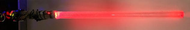
Now when you hit the ignite button the blade will fire up with whatever default setting is in the code – in the above case 255, 0, 0 (pure red) – and the sound will play. When the button is pressed again the extinguish (love using those terms) sound will play and the blade will turn off.
The second button will cause a small flash of the white LED on the colour sensor and grab a reading from something close to it (like holding it near a blue piece of plastic), the next time the saber fires up it should be (approximately) the colour that was picked up.
Finally the board can be removed from USB, plugged into the Powerboost – ensure the power is on for the battery box and the Powerboost and away you go.
The strongest stars have hearts of kyber.
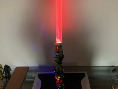
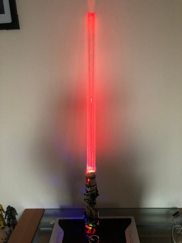
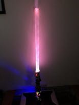
Here is the finished product:
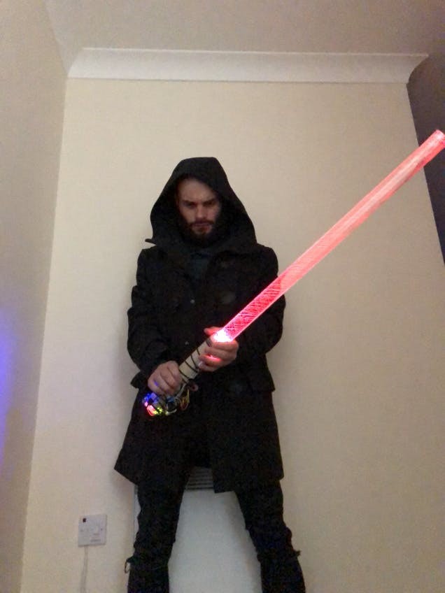
 IMG_5102
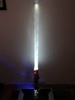
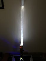
Here’s a couple of other colours I tried with it:
 IMG_5104
 IMG_5105
 IMG_5106
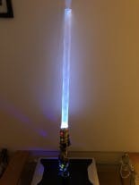 IMG_5107
And of course the video from above with it in action (and having way too much fun):
The Force will be with you. Always.
In the future I’d like to somehow be able to have a non-physical blade; not sure how this would be done – was thinking of something crazy like being able to gather dust using electrostatic or something in a ‘tube’ above the main device, so that the Neopixel LED’s can reflect off of to make a true lightsaber when its on.
The construction could be much better but I’m very happy with the overall results; nothing is cooler than firing up a lightsaber you made yourself. Much like all of my projects this can be considered a prototype and one day I will probably make a much better MKII version.
There was also some issues with picking up the right colour – I found if the surface is too reflective then it will pick up a pure white colour as I think it is reflecting the LED back too much; but the LED is needed to pick up a decent colour sample I think. So best to stick to using matte surfaces for readings.
Let me know what you thought and any improvements you can make, feel free to use the code and designs for your own lightsaber.
Also the Hacksmith people – I'd love to work with you guys on something, I want to try out that super awesome lightsaber you made.
Code
Credits
Related products


Leave your feedback...