
Arduino Led Strip Thermometer And Barometer With Ws2812 A...

Made by Ron / Home Automation / Lights / Sensors / Weather
About the project
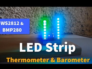
Make a LED Strip Thermometer and Barometer with WS2812 LED strips and BMP280 I2C Sensor. to measure the current temperature and pressure.
Project info
Difficulty: Moderate
Estimated time: 1 hour
License: GNU General Public License, version 3 or later (GPL3+)
Items used in this project
Hardware components

Story
In this tutorial we will learn how to make a LED Strip Thermometer and Barometer with WS2812 LED strips and BMP280 I2C Sensor. to measure the current temperature and atmospheric pressure.
Watch the video!
Step 1: What You Will Need
1 / 5
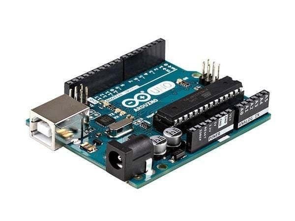
- Arduino UNO (or any other Arduino)
- 2X WS2812 LED strip
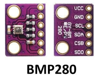
- BMP085 I2C Sensor.
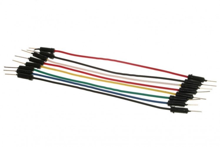
- Jumper wires
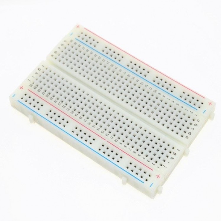
- Breadboard
- Visuino program: Download Visuino
Step 2: The Circuit
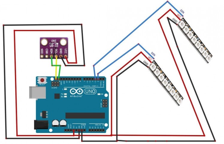
- Connect BMP280 Sensor pin VCC to Arduino pin 5V
- Connect BMP280 Sensor pin GND to Arduino pin GND
- Connect BMP280 Sensor pin SCL to Arduino pin SCL
- Connect BMP280 Sensor pin SDA to Arduino pin SDA
- Connect First LedStrip pin VCC to Arduino pin 5V
- Connect First LedStrip pin GND to Arduino pin GND
- Connect First LedStrip pin DIN to Arduino Digital pin 2
- Connect Second LedStrip pin VCC to Arduino pin 5V
- Connect Second LedStrip pin GND to Arduino pin GND
- Connect Second LedStrip pin DIN to Arduino Digital pin 3
Step 3: Start Visuino, and Select the Arduino UNO Board Type
1 / 2
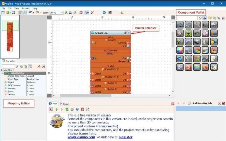
The Visuino: https://www.visuino.eu also needs to be installed. Download Free version or register for a Free Trial.
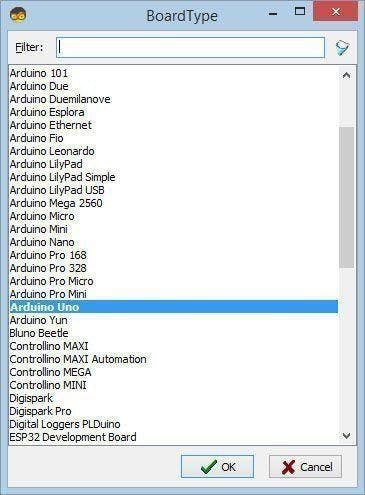
Start Visuino as shown in the first picture Click on the "Tools" button on the Arduino component (Picture 1) in Visuino When the dialog appears, select "Arduino UNO" as shown on Picture 2
Step 4: In Visuino Add Components
1 / 7
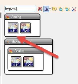

- Add "Pressure Temperature BMP280 I2C" component
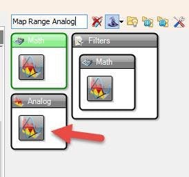
- Add two "Map Range Analog" components
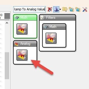
- Add two "Ramp To Analog Value" components
- Add two "Analog To Unsigned" components
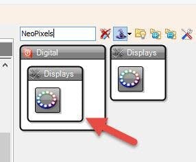
- Add two "NeoPixels" components
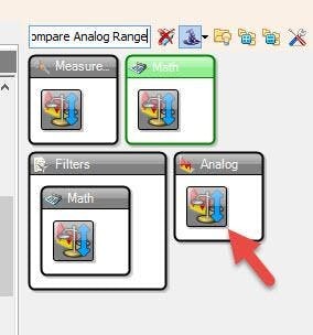
- Add three "Compare Analog Range" components
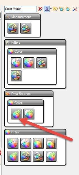
- Add "Color Value" component
Step 5: In Visuino Set Components
1 / 24

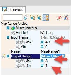


- Select "MapRange1" and in the properties window set Input Range: Max to 40, and Output Range: Max to 8 (this is the number of LEDS on the strip) and Min to 1
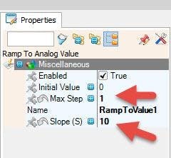
- Select "RampToValue1" and in the properties window set Slope to 10, and Max Step to 1
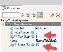
- Select "RampToValue2" and in the properties window set Slope to 10, and Max Step to 1
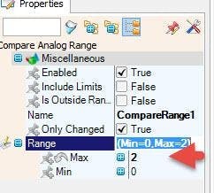
- Select "CompareRange1" and in the properties window set Range: Max to 2
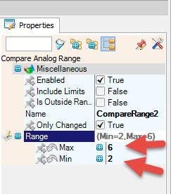
- Select "CompareRange2" and in the properties window set Range: Max to 6 and Min to 2
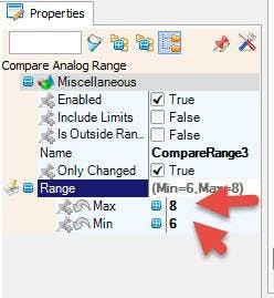
- Select "CompareRange3" and in the properties window set Range: Max to 8 and Min to 6
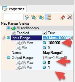
- Select "MapRange2" and in the properties window set Input Range: Max to 100000 (this is the maximum value of the atmospheric pressure you can adjust this value), and Output Range: Max to 8 (this is the number of LEDS on the strip) and Min to 1
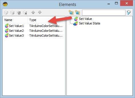
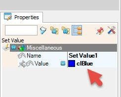
- Double Click on the "ColorValue1" and in the Elements window drag "Set Value" to the left side and in the properties window set Value to clBlue
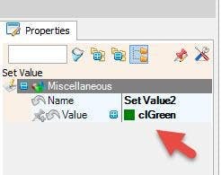
- Drag another "Set Value" to the left side and in the properties window set Value to clGreen
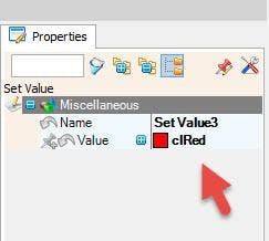
- Drag another "Set Value" to the left side and in the properties window set Value to clRed
- Close the Elements window
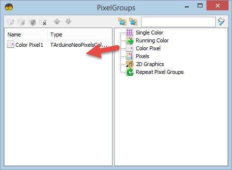
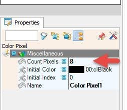
- Double Click on the "NeoPixels1" and in the
- PixelGroups window drag Color Pixel to the left side and in the properties window set Count Pixels to 8 (this is the number of LEDS on the strip)
- Close the PixelGroups window
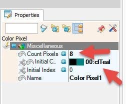
- Double Click on the "NeoPixels2" and in the
- PixelGroups window drag Color Pixel to the left side and in the properties window set Count Pixels to 8 (this is the number of LEDS on the strip), and set "Initial Color" to clTeal
Step 6: In Visuino Connect Components
1 / 3
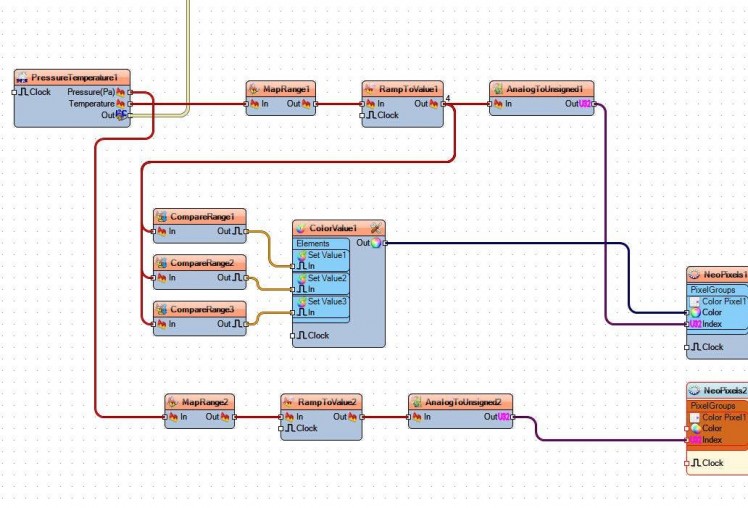
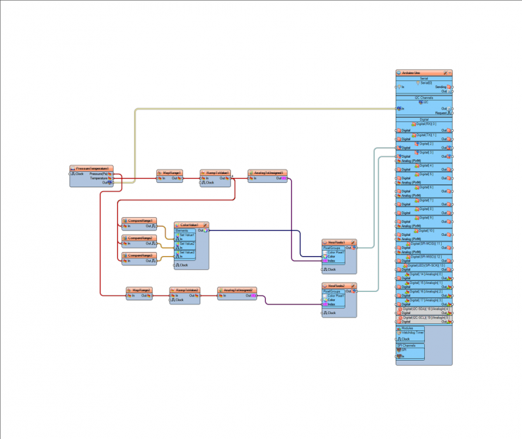
- Connect "PressureTemperature1" pin I2C Out to Arduino board pin I2C In
- Connect "PressureTemperature1" pin Temperature to MapRange1 pin In
- Connect "PressureTemperature1" pin Pressure to MapRange2 pin In
- Connect "MapRange1" pin Out to "RampToValue1" pin In
- Connect "MapRange2" pin Out to "RampToValue2" pin In
- Connect "RampToValue1" pin Out to "CompareRange1", "CompareRange2" and "CompareRange3" pin In
- Connect "RampToValue1" pin Out to "AnalogToUnsigned1" pin In
- Connect "RampToValue2" pin Out to "AnalogToUnsigned2" pin In
- Connect "CompareRange1" pin Out to ColorValue1: Set Value1 Pin In
- Connect "CompareRange2" pin Out to ColorValue1: Set Value2 Pin In
- Connect "CompareRange3" pin Out to ColorValue1: Set Value3 Pin In
- Connect "AnalogToUnsigned1" Pin Out to "NeoPixels1" PixelGroups pin Index
- Connect "AnalogToUnsigned2" Pin Out to "NeoPixels2" PixelGroups pin Index
- Connect "ColorValue1" Pin Out to "NeoPixels1" PixelGroups pin Color
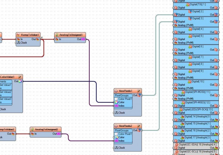
- Connect "NeoPixels1" pin Out to Arduino Digital pin 2
- Connect "NeoPixels2" pin Out to Arduino Digital pin 3
Step 7: Generate, Compile, and Upload the Arduino Code
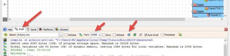
In Visuino, at the bottom click on the "Build" Tab, make sure the correct port is selected, then click on the "Compile/Build and Upload" button.
Step 8: Play
If you power the Arduino module the first LED strip will show the temperature and the second LED strip will show the atmospheric pressure.
Congratulations! You have completed your project with Visuino. Also attached is the Visuino project, that I created for this tutorial, you can download it and open it in Visuino: https://www.visuino.eu
Schematics, diagrams and documents
Code
Credits
Related products


Leave your feedback...