
Drink Temperature Monitor With "invisible" Leds

Made by goscott / 3D Printing / Art / Food & Drinks / Sensors
About the project
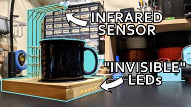
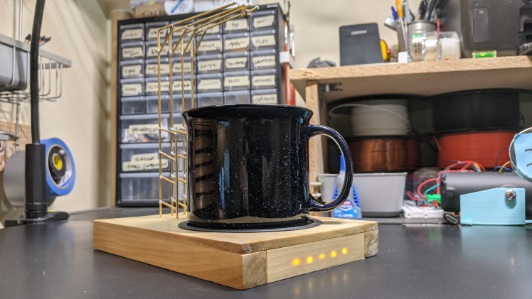
An artsy device that measures the temperature of your drink using an Adafruit infrared sensor supported by a brass sculpture, and displays it using "invisible" LEDs hidden behind a thin layer of wood that aren't visible unless the device is turned on. Powered by an Arduino Nano hidden in the base.
Project info
Difficulty: Easy
Estimated time: 1 day
License: GNU General Public License, version 3 or later (GPL3+)
Items used in this project
Hardware components

View all
Software apps and online services
Hand tools and fabrication machines
View all
Story
Overview
This project was born out of a combination of two ideas: I wanted a device that would let me know when a hot drink had cooled off enough, and I wanted to build something that didn't look at first glance like a piece of electronics, where the wiring was hidden in plain sight or used as decoration rather than purely functionally.
The project consists of a wooden base (poplar, if you’re curious), hiding an Arduino Nano, a battery, and a series of LEDs embedded in the front piece of wood. The Arduino reads temperature data from an Adafruit Melexis infrared sensor that’s supported by a structure built from brass rods, which also acts as the electrical connection between the sensor and the Arduino. There’s a coaster for a mug beneath the switch, in a 3D-printed recess that hides a switch that turns the device on.
The full build process is documented in a YouTube video, which I recommend watching before continuing as it'll give you a better idea of how everything works.
Specific product links for most of the materials used can also be found in the video description.
DISCLAIMER: This project involves keeping exposed live wires next to liquid. Build at your own risk.
The Base
The base is fairly simple, but with one tricky part.
It consists of a 1/4" piece of wood as the top, and 3/4 x 3/4 pieces for the sides, which happens to make the inside just big enough to fit a 9V battery. The dimensions for this are really up to you, as long as the distance between the inside of the inner legs is at least 4", so there's room for the coaster to be inset into the surface.
Cutting the Wood
First, you'll need to cut the wood to size since you're unlikely to find pieces of wood that happen to be the correct size. Again, these sizes are customizable, but I'll document with the sizes I used.
- You'll want to cut the top piece of 1/4" wood first so that it's 8" long (the piece I found was already 5 1/2" wide, but you may need to make a second cut to get to that width).
- Cut two pieces of the 3/4" x 3/4" pieces to match the full length of the top piece (8")
- Cut two pieces of the 3/4" x 3/4" pieces to 4", or whatever the gap between the two long side pieces is when you hold them in place under the top piece of wood.
- Cut a piece of scrap 1/2" thick wood so it's 2" x 3". This will be used as backing for the brass rods, and it's important that it's only 1/2" thick so the brass rods have some room to stick out the bottom without touching the floor.
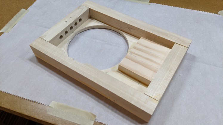
- Cut a 4" diameter hole in the top piece, centered between the long sides of the top and 1 inch from one of the short edges. This short edge is now the "front" of the device.
The "Invisible" LEDs
This is the hardest part of the base, and you may end up needing to re-cut the front piece; any mistake will require you to start this step over. To make the device look as elegant as possible, the LEDs glow through the front piece of wood to indicate the temperature, rather than stick all the way through. This is optional, but the LEDs being hidden unless the device is turned on adds a lot to the effect.
This is achieved by drilling five holes in the back of the front piece of wood, as close to all the way through as possible without actually finishing the hole. I'd recommend doing this with a drill press, although I did it by hand. Don't be discouraged if you accidentally drill too far! I made a second one of these devices as a gift and had to start over on this step three different times before I got it right.
- Mark the center of the piece of wood, and then four other spots (two on each side), spaced out however you like (I separated them by one centimeter).
- Hold your drill bit (1/8" ideally, as it's just a bit bigger than the 3mm LEDs) up to the piece of wood and wrap tape around the bit to help you remember where you need to stop drilling.
- Drill each hole up to the taped mark on your drill bit.
- Knock out all the sawdust and hold the holes up to a bright light. Can you see the light glow through the wood? If you can, you're ready to continue! If not, go make the necessary holes a bit deeper. You really can't be too careful here! The wood needs to be as thin as you possibly can make it, so try to deepen it as little as possible each pass and be prepared to make many passes. If you accidentally go through all the way, you'll need to cut a new front piece and start over.
- Swap out your drill bit for a larger one, around 1/4". Widen the holes, but only until about half way down. This will make getting the LEDs and their wires into the holes much easier.
Gluing
You can now sand the pieces as needed and glue everything together using standard wood glue, and leave clamped to dry overnight (ideally 24 hours). One important note regarding the battery: when you glue in the backing piece you'll want to pinch a 9V battery between the backing piece and one of the sides. This will create a nice press-fit, so you can hold the battery in place without any additional effort (you may need tape if this doesn't work).
Once the glue is dry, you may need to do some additional sanding to remove dried glue marks or fix any rough edges between pieces of wood. Then, apply at least one coat of your preferred waterproof sealant. I used a clear polyurethane, but anything should work. You'll likely want more than one coat as well, and it will probably require another light sanding. Once the coating is dried, the base is complete!
The Coaster
You've drilled the hole for the coaster in the top piece, and you need something to go in it. Attached to the YouTube video and this article is a link to a Thingiverse page that contains the model for the coaster enclosure. You can print this on any 3D printer and in the filament and color of your choosing. I printed it in white because that's what I had on hand, but I wanted it to match the black coasters I had bought so I primed it with filler primer, spray-painted it black, and gave it a protective clear coating. That's all optional, and if you're happy with how it looks right after printing, there's no additional work required here.
If you purchased rubber coasters like I did, you may want to find some scrap balsa wood to superglue to the back of it to make it a bit more rigid. This will help it not get stuck in the "on" position.
The Brass "Sculpture"
Other than the hidden LEDs, this is the part of this project that draws the eye. I tried multiple different ways of supporting the infrared sensor above the drink (check out the YouTube video to see how those ideas went), and this was the best-performing and best-looking solution I found. You're free to play around a bit here, though! The only requirements are:
- There are at least four pieces of some conductive material (brass rods, in my case) that go from the wooden base to the sensor, which must be above the coaster.
- The four conductive pieces must not touch at all, or the circuit won't work (and might be dangerous).
- There must be enough room between the sensor and the coaster for you to fit your favorite mug.
Here's how I did it:
- Draw out a pattern on a piece of paper. You want to avoid curves on this, at least if you're using brass rods. You'll also want to plan on the piece entering the wood in at least two places to keep it from spinning around, and the rods need to stick through the bottom of the backing plate so you'll need at least 3/4" of rod below the top of the base. This is particularly difficult to describe; I'd recommend checking out the video to see it done.
- Scrub any coating off the brass rods with steel wool.
- Cut 2mm brass rods so that you can lay them out on the pattern.
- Tape them down with masking tape.
- Solder the joints together. I'd recommend using the widest tip that you have for your soldering iron, since the brass will take a while to heat up. WARNING: The brass will also take a while to cool down, and it will be very hot. Be careful!
- Once cooled, rub off any gunk that came off of the tape. Steel wool will help with this.
- Repeat this process four times.
Once those are done (and cooled), drill into the wooden base so that each piece can be inserted in parallel. It's important that you drill all the way through for at least one of the legs for each piece, so you can solder to them later on the underside of the device. You may want to add some superglue when you put the rods through the wood to help hold them in place, but this may not be necessary.
At this point, you should have the bulk of the construction complete! All that's left is building the circuit and wiring everything up.
The Wiring
The code and circuit diagram for this project can be found here.
You'll need to upload the code to the Arduino, and configure it so the displayed temperature matches your preferences. That's easy enough to do; you just need to pick a temperature scale (like Celsius, Fahrenheit, or one of the many weird ones the code already supports), and minimum/maximum values. Any temperature at or above the maximum value will be displayed with five LEDs, and anything at or below the minimum value will only be displayed with one.
- Configure the code (you can do this post-assembly as well, as long as you can still plug into the Arudino).
- Upload the code to the Arduino. This can be done with the Arduino IDE, or your preferred method.
- Solder everything together, according to the circuit diagram.
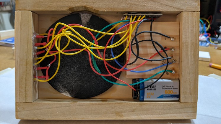
Some things to keep in mind while soldering:
- I recommend testing the circuit out on a breadboard first; it's much easier to catch a mistake there than after you've soldered!
- The wires for the switch need to go through the holes in the coaster enclosure, AND through the hole in the top of the base. If you forget to do this (like I did), you won't be able to get the switch inserted properly and you'll need to cut and re-attach the wires.
- Keep track of which LED is which, since you'll want to insert them into the wooden base in order.
- To positive ends of the LEDs can all be shorted together, which cuts down on how many wires you need to manage.
- Try not to use wires that are too long! They don't need to reach that far, and a huge bundle of wires under your device can get pretty annoying.
- Soldering the infrared sensor to the brass rods can be tricky. Do your best to hold it in place, and bend the sensor's wires ahead of time so it's held in place by gravity as much as possible.
Assembly
You're almost done! The following steps can be done in any order, and when these are done, so are you!
- Glue the coaster enclosure into the wooden base with superglue, with the switch lined up in the center and as close to the brass as possible.
- Glue the LEDs into the wooden front piece with super glue. You may want to then fill up the rest of the holes with super glue to ensure that the LEDs are really well stuck.
- Put the coaster in the enclosure.
- Re-calibrate the Arduino as necessary until you're happy with the temperature range.
Final Thoughts
This was a very fun project to build, I'm really happy with how it looks and it's getting daily use. I hope you enjoyed, and I'd love to see what you come up with if you decide to build your own. I've got some other fun projects in the pipeline as well, check back later to see what else I've been working on if you liked this one. Happy making!
CAD, enclosures and custom parts
Code
Credits
Related products


Leave your feedback...