
Arduino Display Time On Tm1637 Led Display Using Rtc Ds1307

About the project
In this tutorial we will learn how to display time using RTC DS1307 module and LED Display TM1637 and Visuino.
Project info
Difficulty: Easy
Platforms: Arduino, SparkFun, Visuino
Estimated time: 1 hour
License: GNU General Public License, version 3 or later (GPL3+)
Items used in this project
Hardware components

Story
In this tutorial we will learn how to display time using RTC DS1307 module and LED Display TM1637 and Visuino.
Watch the video.
Step 1: What You Will Need
1 / 5

- Arduino UNO (or any other Arduino)
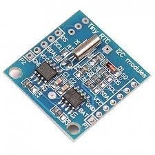
- RTC DS1307 module
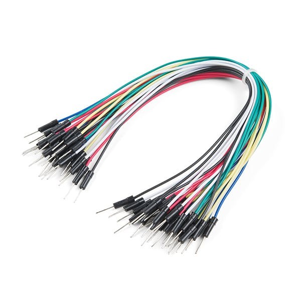
- Jumper wires
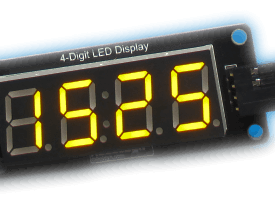
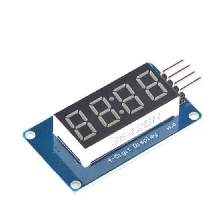
- LED Display TM1637
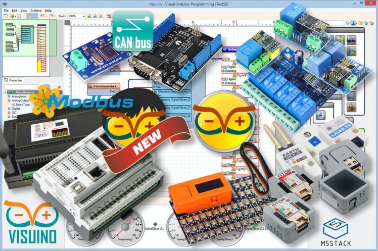
- Visuino program: Download Visuino
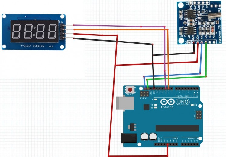
- Connect LED Display pin[CLK] to Arduino digital pin[10]
- Connect LED Display pin[DI0] to Arduino digital pin[9]
- Connect LED Display pin[GND] to Arduino pin[GND]
- Connect LED Display pin[VCC] to Arduino pin[5V]
- Connect RTC DS1307 module pin[VCC] to Arduino pin[5V]
- Connect RTC DS1307 module pin[GND] to Arduino pin[GND]
- Connect RTC DS1307 module pin[SDA] to Arduino pin[SDA]
- Connect RTC DS1307 module pin[SCL] to Arduino pin[SCL]
1 / 2
To start programming the Arduino, you will need to have the Arduino IDE installed from here: https://www.arduino.cc/.
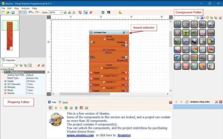
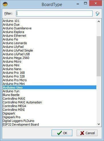
Please be aware that there are some critical bugs in Arduino IDE 1.6.6. Make sure that you install 1.6.7 or higher, otherwise this tutorial will not work! If you have not done follow the steps in this tutorial to setup the Arduino IDE to program Arduino UNO! The Visuino: https://www.visuino.eu also needs to be installed. Start Visuino as shown in the first picture Click on the "Tools" button on the Arduino component (Picture 1) in Visuino When the dialog appears, select "Arduino UNO" as shown on Picture 2
Step 4: In Visuino ADD Components
1 / 6
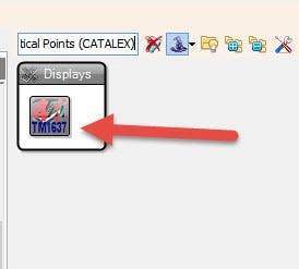
- Add "TM1637 7 Segment Display 4 Digits Module + 2 Vertical Points (CATALEX)" component
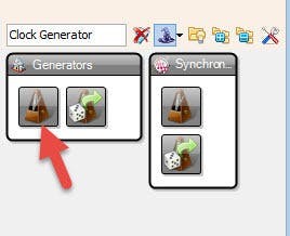
- Add "Clock Generator" component
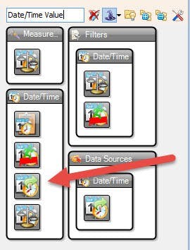
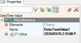
- Add "Date/Time Value" component
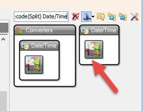
- Add "Decode(Split) Date/Time" component
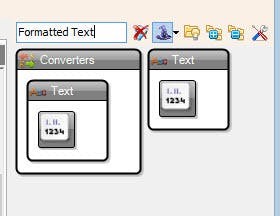
- Add "Formatted Text" component
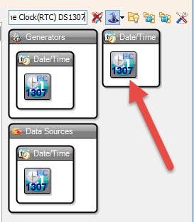
- Add "Real Time Clock(RTC) DS1307" component
- Add "Pulse generator" component
1 / 4
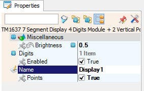
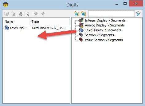
- Double click on "Display1" component and in the "Digits" window drag "Text Display 7 Segments" to the left sideOn the left side of the "Digits" window select "Text Display 7 Segments1" and in the properties window set "Count Digits" to 4
- Close the "Digits" window
- Select "DateTimeValue1" and in the properties window set "Value" to current date and time
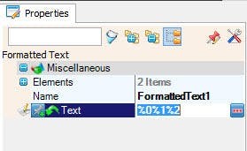
- Double click on "FormattedText1" component and in the elements window drag 2x "Text element" to the left side, for both set in the properties window "Length" to 2
- Select "FormattedText1" and in the properties window set "Text" to %0%1%2
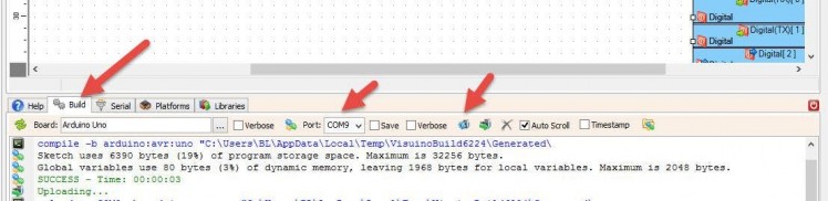
In Visuino, at the bottom click on the "Build" Tab, make sure the correct port is selected, then click on the "Compile/Build and Upload" button.
Step 7: PlayIf you power the Arduino UNO module, the LED display should start showing the time.
Congratulations! You have completed your project with Visuino. Also attached is the Visuino project, that I created for this tutorial, you can download it here and open it in Visuino: https://www.visuino.eu
Step 8: In Visuino: Connect Components- Connect ClockGenerator1 pin out to RealTimeClock1 pin Clock
- Connect DateTimeValue1 to RealTimeClock1 pin Set
- Connect RealTimeClock1 pin Out to DecodeDateTime1 pin In
- Connect RealTimeClock1 pin Control I2C to Arduino board pin I2C In
- Connect DecodeDateTime1 pin Hour to FormattedText1> Text Element1 pin In
- Connect DecodeDateTime1 pin Minute to FormattedText1> Text Element2 pin In
- Connect FormattedText1 pin Out to Display1>Text Display 7 Segments1> Pin In
- Connect Display1 pin Clock to Arduino board digital Pin 10
- Connect Display1 pin Data to Arduino board digital Pin 9
Schematics, diagrams and documents
Code
Credits
Related products


Leave your feedback...