
Arduino And Visuino: Use Lego Mindstorm Rcx Light Sensor

Made by Ron / Games & Gaming / Home Automation / Robotics / Sensors
About the project
We all love LEGO, and many of us have old LEGO Mindstorm sets. Why not use the Light Sensor from the set with Arduino?
Project info
Difficulty: Easy
Estimated time: 1 hour
License: GNU General Public License, version 3 or later (GPL3+)
Items used in this project

Story
In this Tutorial you will learn how to program Arduino to control, and get data from LEGO Mindstorm RCX Light Sensor with the help of Visuino - an easy to use graphical development environment for Arduino.
Step 1: Components
- One Arduino board (I use Arduino MEGA in this tutorial, just because I have one available, but any other will work)
- One LEGO Mindstorm RCX Light Sensor (From an old LEGO set)
- 2 or 3 male-male jumper wires
1 / 4 • Picture 1

Picture 1

Picture 2

Picture 3

Picture 4
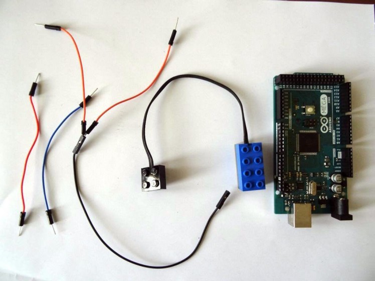
- Connect 2 wires to the 2 metal strips(plates) on the bottom of the electrical connection LEGO block as shown in the (Picture 1)
- Connect the single wire from the sensor to the Arduino Ground as shown in (Picture 2)
Arduino UNO:
- Connect the second wire to the Arduino Analog 0 pin (On Arduino UNO Analog 0 and Digital 14 are the same pin) (Picture 3)
Arduino MEGA:
- If you use Arduino MEGA as in my case, split the secondwire into 2 wires. You can use a Female-Female wire as I did or a Breadboard
- Connect one of the split wires to the Digital 14 pin as shown in (Picture 2)
- Connect the other one to Analog 0 pin (Picture 3)
You can see the Arduino MEGA connected on (Picture 4) . In my case I used a spare LEGO wire so I can experiment easily with different sensors. This is not needed for this project, so you can connect directly to the sensor without the additional wire.
Step 3: Start Visuino, and select the Arduino board
1 / 2 • Picture 1

Picture 1

Picture 2
To start programming the Arduino, you will need to have the Arduino IDE installed from here: http://www.arduino.cc/.
Please be aware that there are some critical bugs in Arduino IDE 1.6.6.
Make sure that you install 1.6.7 or higher, otherwise this Tutorial will not work!
The Visuino: https://www.visuino.com also needs to be installed.
- Start Visuino as shown in the first picture.
- Click on the tools button on the Arduino component in Visuino, and when the dialog appears, select your Arduino board type as shown in Picture 2 (In my case I selected Arduino Mega)
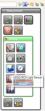
- From the toolbar expand the "Measurement" Category, then the "Analog" Sub Category, and select the "LEGO RCX Light Sensor" as shown on the picture
- Then drop the component in the design area

Connect the "Charge" output pin of the Light Sensor component to the "Digital" input pin of the "Digital[14]" of the Arduino component as shown on the picture
Step 6: Connect the LEGO component's Sensor Analog Pin in Visuino
1 / 2 • Picture 1

Picture 1

Picture 2
Connect the "Sensor" input pin of the Light sensor (Picture 1) to the "Out" pin of the "AnalogInput[ 0 ]" channel of the Arduino component (Picture 2)
Step 7: Connect the LEGO component's Analog Output Pin to the serial port in Visuino
1 / 2 • Picture 1

Picture 1

Picture 2
- Connect the "Out" pin of the Light Sensor (Picture 1)
- To the "In" pin of the "Serial[ 0 ]" on the Arduino component (Picture 2)
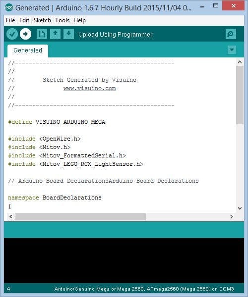
- In Visuino press the F9 key. This will generate the Arduino code and start the Arduino IDE
- Connect your Arduino board, with the USB cable
- Click on the Upload button in the Arduino IDE to compile, and upload the sketch
1 / 3 • Picture 1

Picture 1

Picture 2

Picture 3
- In Visuino select the Serial port to which the Arduino is connected, then click on the "Connect" button (Picture 1)
- You will see the data arriving from the sensor in the Terminal (Picture 2)
- You can also switch to the Scope tab to see the data plotted in the Scope (Picture 3)
Now we will extend it, to turn ON the pin 13 LED of the Arduino board when the sensor is over white surface.
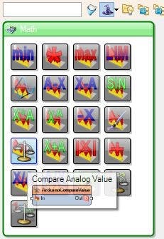
- From the toolbar expand the "Math" Category, and select the "Compare Analog Value" as shown on the picture
- Then drop the component in the design area
1 / 3 • Picture 1

Picture 1

Picture 2

Picture 3
- Connect the "Out" pin of the Light Sensor to the "In" pin of the Compare Analog Value component (Picture 1)
- Connect the "Out" pin of the Compare Analog Value component to the "Digital" pin of the "Digital[ 13 ]" channel (Picture 2)
- In the object inspector, set the "CompareType" to ctBigger
- In the object inspector, set the "Value" property to between 0.25 to 0.35 ( you may need to experiment to find the best value) (Picture 3)
1 / 2 • Picture 1

Picture 1

Picture 2
- Move the sensor over black, and while surface.
- If the sensor is over black surface, the LED on pin 13 will turn off (Picture 1)
- If the sensor is over white surface, the LED on pin 13 will turn on (Picture 2)
Congratulations! You created your own Arduino program to read data from LEGO Mindstorm RCX Light Sensor in just few minutes!
Also attached is the Visuino project, that I created for this Tutorial. You can download and open it in Visuino: https://www.visuino.com
Credits
Related products


Leave your feedback...