
Arduino And Visuino: Control Servo With Buttons

Made by Ron / Home Automation / Robotics / Sensors
About the project
There are a lot of tutorials, on how to control Servos with joysticks, or analog sensors, but sometimes we need to control them with buttons
Project info
Difficulty: Easy
Platforms: Arduino, SparkFun, Visuino
Estimated time: 1 hour
License: GNU General Public License, version 3 or later (GPL3+)
Items used in this project
Hardware components

Story
While there are a lot of tutorials, on how to control Servos with joysticks, and analog sensors, sometimes we want to control a servo with buttons.
Here is a really easy and quick way to achieve this, with the help of Visuino - an easy to use and powerful graphical development environment for Arduino.
Step 1: Components
1 / 2 • Picture 1

Picture 1

Picture 2
- One Arduino board (I used Mega because I had one available, but ONO will be perfectly fine)
- One Breadboard
- 2 Push Buttons
- 2 10K resistors
- One Servo (I used SG90)
- Few jumper wires
- Optionally: one Breadboard power supply
1 / 3 • Picture 1

Picture 1

Picture 2

Picture 3
- Install the 2 push buttons on the Breadboard (Picture 1)
- Connect the Resistors between one ends of the buttons, and Ground on the Breadboard Power Bus (Picture 2)
- Connect jumper wires between the other ends of the buttons and Power on the Breadboard Power Bus (Picture 3)
1 / 4 • Picture 1

Picture 1

Picture 2

Picture 3

Picture 4
- Connect 2 jumper wires (Green and White wires on Picture 1) to the same connection point on the buttons where the 2 resistors are connected (Picture 1)
- Connect the other end of one of the wires (Green wire) to Digital Pin 2 of the Arduino Board (Picture 2)
- Connect the other end of the second wire (White wire) to Digital Pin 3 of the Arduino Board (Picture 2)
- Connect 2 wires to the Power (Red wire) and Ground (Black wire) of he Breadboard Power Bus (Picture 3)
- Connect the other end of the Power (Red wire) wire to the 5V power pin of the Arduino Board (Picture 4)
- Connect the other end of the Ground (Black wire) wire to the Ground pin of the Arduino Board (Picture 4)
1 / 6 • Picture 1

Picture 1

Picture 2

Picture 3

Picture 4

Picture 5

Picture 6
- Attach the Breadboard Power Supply to the Breadboard on the side opposite to the buttons as seen on pictures 4 and 5
- Connect a jumper wire between the Grounds of the two Power Buses on the Breadboard as shown on Picture 1
- Add Ground(Black wire), Power(Red wire), and Control(Yellow wire) to the Servo connector (Picture 2, and 3)
- Connect the other end of the Ground(Black wire), and Power(Red wire) to the separated power bus on the Breadboard(Picture 4) . If you decide to power the Servo directly from Arduino, connect to the same Breadboard power bus, where the Buttons are connected
- Connect the other end of the Control(Yellow wire) to the Digital Pin 4 of the Arduino Board (Picture 5)
1 / 3 • Picture 1

Picture 1

Picture 2

Picture 3
To start programming the Arduino, you will need to have the Arduino IDE installed from here: http://www.arduino.cc/ .
Please be aware that there are some critical bugs in Arduino IDE 1.6.6. Make sure that you install 1.6.7 or higher, otherwise this Tutorial will not work!
The Visuino: https://www.visuino.com also needs to be installed.
- Start Visuino
- Type "clo" in the Filter box of the Component Toolbox then select the "Clock Generator" component (Picture 1), and drop two of them in the design area
To Enable/Disable the generators we need to add pins to the Enabled property of the components:
- Select the ClockGenerator1 in the design area. In the Object Inspector click on the Pin button at front of the Enabled property, and select "Boolean SinkPin" (Picture 2)
- Select the ClockGenerator2 in the design area. In the Object Inspector click on the Pin button at front of the Enabled property, and select "Boolean SinkPin" (Picture 3)
1 / 5 • Picture 1

Picture 1

Picture 2

Picture 3

Picture 4

Picture 5
- Type "count" in the Filter box of the Component Toolbox then select the "Up/Down Counter" component (Picture 1), and drop it in the design area
- Connect the components as shown on Picture 2
- In the Object Inspector expand the Counter's Min property, then set the RollOver sub property to False, and the Value sub property to 0 (Picture 3)
- In the Object Inspector expand the Counter's Max property, then set the RollOver sub property to False, and the Value sub property to 200 (Picture 4)
- Select the the Clock Generators, and in the Object Inspector set the Enabled property to False, and the Frequency property to 40 (Picture 5)
1 / 3 • Picture 1

Picture 1

Picture 2

Picture 3
- Type "Inte" in the Filter box of the Component Toolbox then select the "Integer To Analog" component (Picture 1), and drop it in the design area
- In the Object Inspector set the Scale property to 0.005 (Picture 2) . This will convert the counter values from the integer range of 0 to 200, to the analog range of 0.0 to 1.0.
- Connect the "Out" pin of the UpDownCounter1 to the "In" pin of the IntegerToAnalog1 component (Picture 3)
1 / 4 • Picture 1

Picture 1

Picture 2

Picture 3

Picture 4
- From the Component Toolbox expand the "Motors" Category, and select the "Servo" component as shown on the first picture, then drop it in the design area
- Connect the "Out" pin of the IntegerToAnalog1 component to the "In" pin of the Servo1 component (Picture 2)
- Connect the "Out" pin of the Servo1 (Picture 3) to the "Digital" input pin of the Digital[ 4 ] channel of the Arduino component (Picture 4)
1 / 2
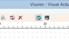
- In Visuino, Press F9 or click on the button shown on Picture 1 to generate the Arduino code, and open the Arduino IDE
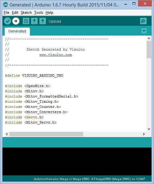
- In the Arduino IDE, click on the Upload button, to compile and upload the code (Picture 2)
1 / 3 • Picture 1

Picture 1

Picture 2

Picture 3
Congratulations!
The project is completed. You can use the buttons to control the servo. If you press and hold one of the buttons the servo will move in one direction until it reaches the end position. If you press and hold the other button the servo will move in the opposite direction until it reaches the end position.
On Picture 3 you can see the complete Visuino diagram.
Enjoy your servo control :-)
Also attached is the Visuino project, that I created for this Tutorial. You can download and open it in Visuino: https://www.visuino.com
Credits
Related products


Leave your feedback...