
Arduino Ambient Light With 433mhz Rf Remote Control

Made by Ron / Communication / Displays / Home Automation / Lights / Robotics
About the project
In this tutorial we will learn how to control the RGB LED Random color with a 433MHz RF Remote and Arduino, also how to turn it ON or OFF, o
Project info
Difficulty: Easy
Estimated time: 1 hour
License: GNU General Public License, version 3 or later (GPL3+)
Items used in this project
Hardware components

Story
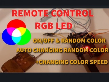
In this tutorial we will learn how to control the RGB LED Random color with a 433MHz RF Remote and Arduino, also how to turn it ON or OFF, or set the auto changing color and the speed of the changing color.
Watch the Video!
Step 1: What You Will Need
1 / 5
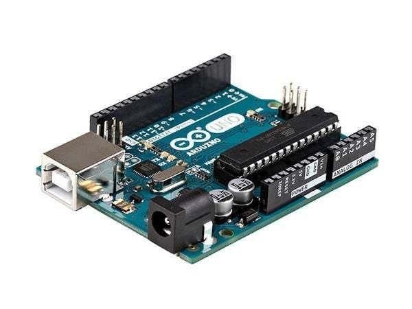

- Arduino UNO (or any other Arduino)
- Jumper wires
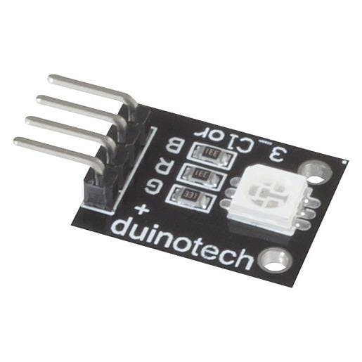
- RGB LED Module
- 433 MHz RF module
- Visuino program: Download Visuino
Step 2: The Circuit
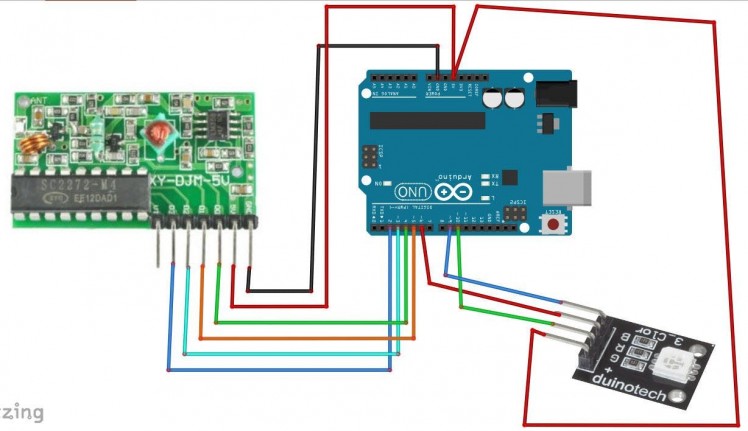
- Connect Remote pin [VCC] to Arduino pin [5V]
- Connect Remote pin [GND] to Arduino pin [GND]
- Connect Remote pin [D0] to Arduino digital pin [4]
- Connect Remote pin [D1] to Arduino digital pin [5]
- Connect Remote pin [D2] to Arduino digital pin [3]
- Connect Remote pin [D3] to Arduino digital pin [2]
- Connect RGB LED pin [+] to Arduino pin [5V]
- Connect RGB LED pin [R] to Arduino digital pin [6]
- Connect RGB LED pin [G] to Arduino digital pin [10]
- Connect RGB LED pin [B] to Arduino digital pin [9]
Note: some RGB LED modules have pin (-) instead of pin (+) in that case you connect it to the Arduino pin [GND]
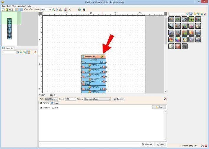
Step 3: Start Visuino, and Select the Arduino UNO Board Type
1 / 2
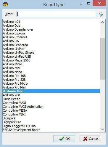
The Visuino: https://www.visuino.eu also needs to be installed. Download Free version or register for a Free Trial.
Start Visuino as shown in the first picture Click on the "Tools" button on the Arduino component (Picture 1) in Visuino When the dialog appears, select "Arduino UNO" as shown on Picture 2
Step 4: In Visuino Add, Set & Connect Components
1 / 20
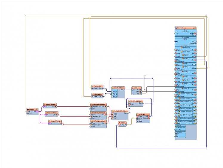
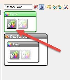
- Add "Random Color" component
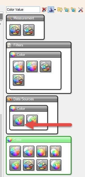
- Add "Color Value" component
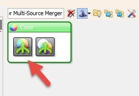
- Add "Color Multi-Source Merger" component
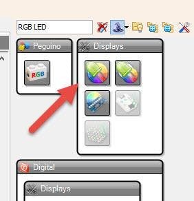
- Add "RGB LED" component
Note: If the LED is not shining then Select "LED1" and in the properties window set "Inverted" to True
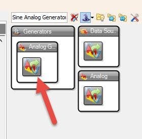
- Add "Sine Analog Generator" component
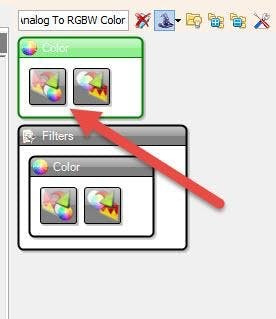
- Add "Analog To RGBW Color" component
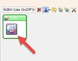
- Add "RGBW Color On/Off Switch" component
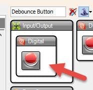
- Add "Debounce Button" component
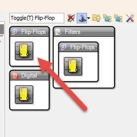
- Add "Toggle(T) Flip-Flop" component
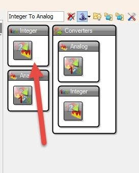
- Add 3X "Integer To Analog" component
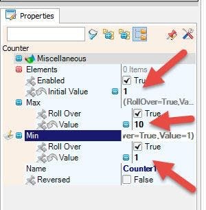
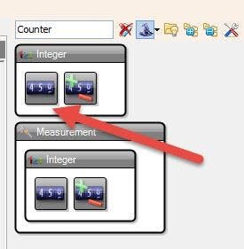
- Add "Counter" component
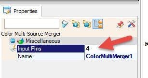
- Select "ColorMultiMerger1" and in the properties window set "Input Pins" to 4
- Select "Counter1" and in the properties window set "Initial Value" to 1 , Max > Value to 10, Min > Value to 1
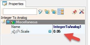
- Select "IntegerToAnalog1" and the properties window set Scale to 0.05
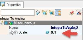
- Select "IntegerToAnalog2" and the properties window set Scale to 0.1
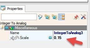
- Select "IntegerToAnalog3" and the properties window set Scale to 0.05
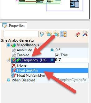
- Select "SineAnalogGenerator1" and the properties window click on the "Frequency" pin icon and select "Float SinkPin"
- Select "SineAnalogGenerator2" and the properties window click on the "Frequency" pin icon and select "Float SinkPin"
- Select "SineAnalogGenerator3" and the properties window click on the "Frequency" pin icon and select "Float SinkPin"
- Connect Arduino digital Out pin[4] to "ColorValue1" pin [Clock] , this will be used to turn the LED Off
- Connect Arduino digital Out pin[5] to "RandomColor1" pin [Clock] , this will be used to set the random color on the LED
- Connect Arduino digital Out pin[2] to "Counter1" pin [In] , this will be used to set the color changing speed on the LED
- Connect Arduino digital Out pin[3] to "Button1" pin [In] , this will be used to turn ON/OFF the auto color changing on the LED
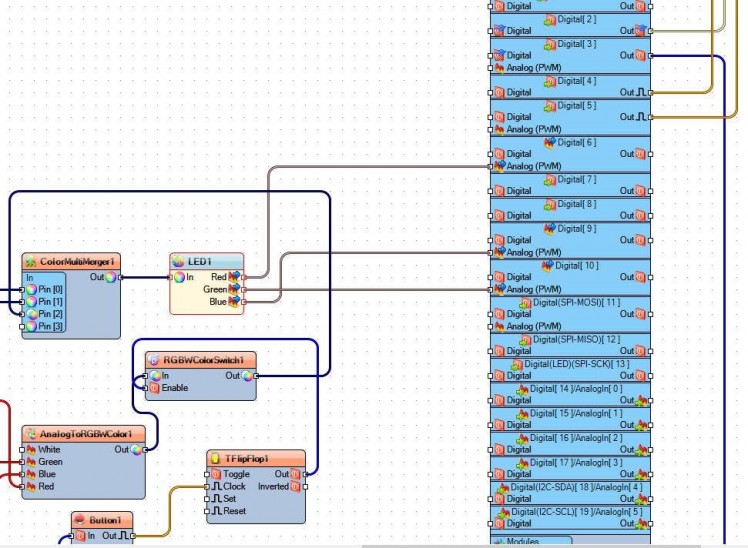
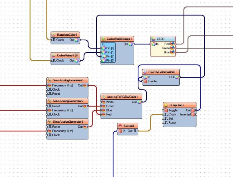
- Connect "RandomColor1" pin [Out] to "ColorMultiMerger1" pin [0]
- Connect "ColorValue1" pin [Out] to "ColorMultiMerger1" pin [1]
- Connect "ColorMultiMerger1" pin [Out] to "LED1" pin [In]
- Connect "LED1" pin[Red] to Arduino Digital-Analog PWM pin[6]
- Connect "LED1" pin[Green] to Arduino Digital-Analog PWM pin[10]
- Connect "LED1" pin[Blue] to Arduino Digital-Analog PWM pin[9]
- Connect "Counter1" pin [Out] to "IntegerToAnalog1" pin [In] and "IntegerToAnalog2" pin [In] and "IntegerToAnalog3" pin [In]
- Connect "IntegerToAnalog1" pin [Out to "SineAnalogGenerator1" pin [Frequency]
- Connect "IntegerToAnalog2" pin [Out to "SineAnalogGenerator2" pin [Frequency]
- Connect "IntegerToAnalog3" pin [Out to "SineAnalogGenerator3" pin [Frequency]
- Connect "SineAnalogGenerator1" pin [Out] to "AnalogToRGBWColor1" pin [Red]
- Connect "SineAnalogGenerator2" pin [Out] to "AnalogToRGBWColor1" pin [Green]
- Connect "SineAnalogGenerator3" pin [Out] to "AnalogToRGBWColor1" pin [Blue]
- Connect "AnalogToRGBWColor1" pin [Out] to "RGBWColorSwitch1" pin [In]
- Connect "Button1" pin [Out] to "TFlipFlop1" pin [Clock]
- Connect "TFlipFlop1" pin [Out] "RGBWColorSwitch1" pin [Enable]
- Connect "RGBWColorSwitch1" pin [Out] to "ColorMultiMerger1" pin[3]
Step 5: Generate, Compile, and Upload the Arduino Code
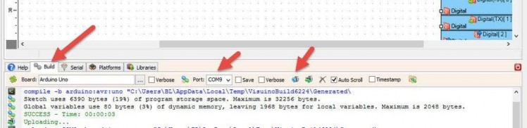
In Visuino, at the bottom click on the "Build" Tab, make sure the correct port is selected, then click on the "Compile/Build and Upload" button.
Step 6: Play
If you power the Arduino module, and press the button "A" on the Remote the LED will Turn ON and a random color will shine, If you press the button "B" on the Remote the LED will turn off.
If you press the button "C" on the Remote the color will start to change on the LED.
If you press the button "D" on the Remote the speed of the color changing will change.
Congratulations! You have completed your project with Visuino. Also attached is the Visuino project, that I created for this Tutorial, you can download it and open it in Visuino: https://www.visuino.eu
Schematics, diagrams and documents
Code
Credits
Related products


Leave your feedback...