

555 Pulse Generator Module, How It Works

Made by tarantula3 / Home Automation / Lights / Productivity / Robotics / Sensors
About the project
The 555 timer IC is an integrated circuit that is used in a variety of timer circuits, pulse generators and oscillator applications.
Project info
Difficulty: Easy
Platforms: Adafruit, Android, Arduino, Maxim Integrated, Helium
Estimated time: 1 hour
License: GNU General Public License, version 3 or later (GPL3+)
Items used in this project

Story
The 555 timer IC is an integrated circuit that is used in a variety of timer circuits, pulse generators and oscillator applications. The heart of the module is the 555 timer IC that is wired as an astable multivibrator, generating pulses from about 4Hz to 1.3Khz.
This circuit can be used in any project, that requires positive pulses.
To demonstrate the operation, a LED is used at the output of the IC to show the visual indication of the output pulses.
The output frequency of pulses can be adjusted using a potentiometer. The circuit can be operated from any voltage between 5 to 15 volt DC.
For this project we need:
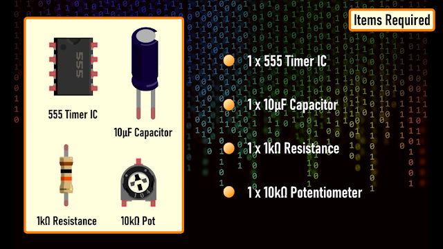
- 1 x 555 Timer IC
- 1 x 10µF Capacitor
- 1 x 1kΩ Resistance and a
- 1 x 10kΩ Potentiometer
Circuit Diagram

The circuit is very simple.
By connecting pin 2 and 6 we put the 555 timer in astable mode. Astable mode causes the 555 timer to re-trigger itself, producing a stream of pulses [PWM Signals] as long as its hooked up to a power supply.
Pin number 3 is the output pin. By changing the values of R1, R2, and C3 we can change the frequency of output pulses generated at pin number 3.
How It Works
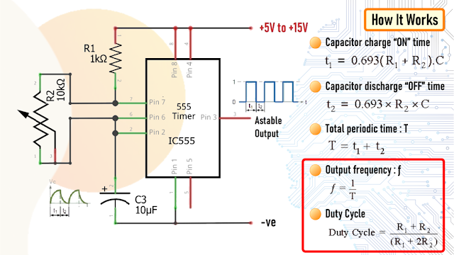
The working voltage of the circuit is between 5V~15V DC.
As previously discussed 555 timer generates PWM signals when set up in an astable mode by connecting the pin 2 and 6 together.
During each cycle capacitor C3 charges up through both R1 and R2 resistors but discharges itself only through resistor R2 as the other side of R2 is connected to the discharge terminal pin 7.
Changing the values of R1, R2, and C3 will change the frequency of output pulses, or different duty cycle of the square wave coming out of pin 3.
By changing the value of R2 we can change the duration of the OFF cycle.
In this setup the ON time depends on the resistor R1, the left side of the pot and the capacitor C3, while the OFF time depends on the capacitor C3 and the right side of the pot.
Now, lets calculate the output frequency and the duty cycle of the output waveform.
In my setup I have resistance R1 = 1kΩ, R2 = 10kΩ and capacitor C = 10uF
There are many online calculators to calculate this online. I will provide a link to one of the astable calculators in the description below: https://ohmslawcalculator.com/555-astable-calculator
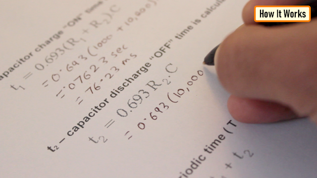
Lets first calculate the value of t1 or the 'capacitor charge “ON” time which is 0.693(R1 + R2 ) * C3. Putting the values together we get 76.23 milliseconds.
Now, for capacitor discharge “OFF” time or t2 we need to multiply 0.693 to R2 and C3, which then gives us a value of 69.3 milliseconds.
Next, the total periodic time T is equal to t1 + t2 which comes out to be 145.53 milliseconds.

The output frequency, ƒ is therefore comes out to be to 6.871Hz.

Which gives a duty cycle value of 52.38%
If you want to have more control over the charging and discharging use a higher value for R2 (100K) and lower value for R1 (1K). That way you will have 99% control over the charging and discharging resistance in the circuit.
The maximum output current of this IC is 200mA therefore to drive a higher current load of up to 1A we have to use a transistor like the BD135.
For driving a much higher current than 1A you can use other high current transistors like TIP31, 2N3055, etc. with a good heatsink. TIP122 can only go up to about 1.5 amps without a heatsink, however it can go up to 5 amps with a good heatsink. IRLB8743 FET is good to around 20 amps without a heatsink.
The Board


Soldering
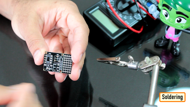
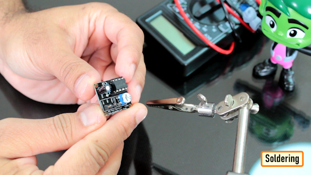
To conclude I have soldered 3 x Male pin headers to the board.
Demo

Applications and Uses
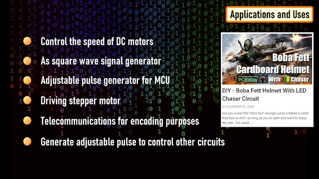
- This circuit can be used to control the speed of DC motors
- As square wave signal generator
- Adjustable pulse generator for MCU
- Driving stepper motor
- Telecommunications for encoding purposes
- Generate adjustable pulse to control other circuits
I have used this in few of my projects like:
Thanks
Thanks again for checking my post. I hope it helps you.
If you want to support me subscribe to my YouTube Channel: https://www.youtube.com/user/tarantula3
Full Blog Post: https://diy-projects4u.blogspot.com/2021/07/555-pulse-generator-module-how-it-works.html
Video: https://youtu.be/bMAnipPOjFo
Related Videos:
1. DIY - Boba Fett Helmet With LED Chaser Circuit : https://youtu.be/vtO_GD0SS2s
2. LED Chaser Circuits Using IC4017 and Arduino : https://youtu.be/F6V1AjESWbU
3. DIY - LAN CABLE TESTER : https://youtu.be/PSK5Aa-byHA
Gerber File: https://drive.google.com/file/d/1YE5vznhAcQx2cmlXouRhn2yxZB3Lb2RK/view?usp=sharing
Calculator: https://drive.google.com/file/d/17dTw22opXIw8WI4-knUZu4rr6k-6zlxV/view?usp=sharing
Schema: https://drive.google.com/file/d/1K635sLu-J3UQzEibjANlfm8ywCgy4tJ0/view?usp=sharing
Support My Work
- BTC: 1M1PdxVxSTPLoMK91XnvEPksVuAa4J4dDp
- LTC: MQFkVkWimYngMwp5SMuSbMP4ADStjysstm
- DOGE: DDe7Fws24zf7acZevoT8uERnmisiHwR5st
- ETH: 0x939aa4e13ecb4b46663c8017986abc0d204cde60
- BAT: 0x939aa4e13ecb4b46663c8017986abc0d204cde60
- LBC: bZ8ANEJFsd2MNFfpoxBhtFNPboh7PmD7M2
Thanks, ca again in my next tutorial.
Credits
Related products


Leave your feedback...