
What is the Gemma M0 and CircuitPython?
MicroPython has come a long way since Damien George first released his Kickstarter for the PyBoard in 2014. Originally a fork of Python 3 for microcontrollers we now have a mature Micro Python platform available for a diverse range of boards such as the BBC micro:bit, WiPy, and ESP32 and this range keeps growing. Adafruit, the American maker company has long been a supporter of the maker community, and in recent months they have released their own “fork” of the MicroPython project and it is called CircuitPython.
So what is CircuitPython?
CircuitPython is a simplified version of MicroPython designed for users to just plug in a compatible board, write some code and see the results. No downloads, configuration are required. CircuitPython has been created to enable anyone to take their first steps with Python and create physical projects.
And who is Gemma M0?
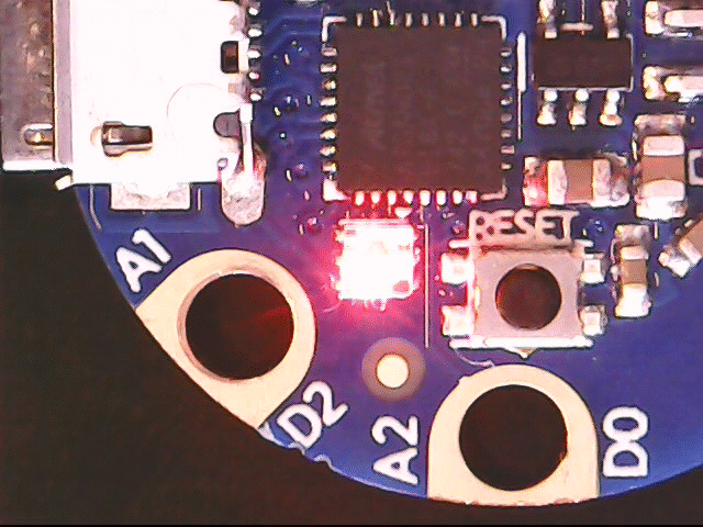
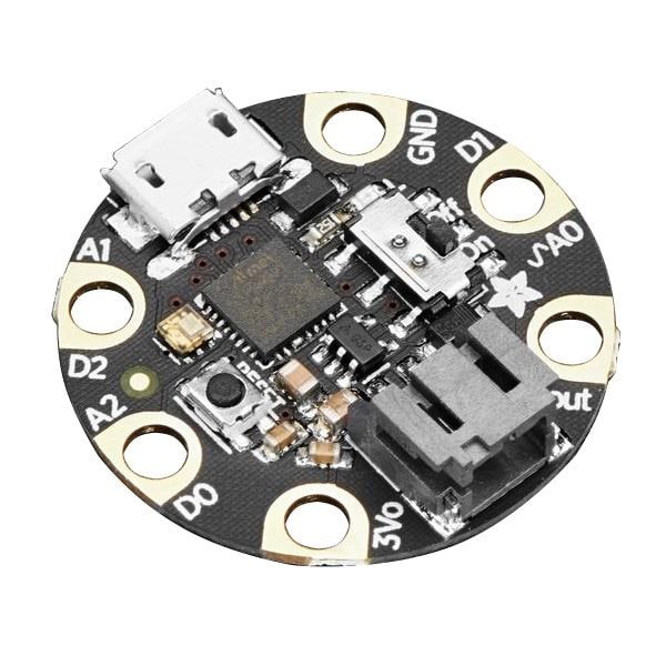
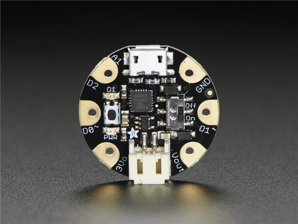
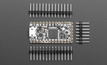
Gemma is not a person, rather a basic wearable board developed by Adafruit. Originally based upon the ATtiny85, itself a great and cheap platform for Arduino projects, the Gemma M0 replaces the Attiny85 with an ATSAMD21E18 32-bit Cortex M0+ for a much more powerful board, in a tiny package.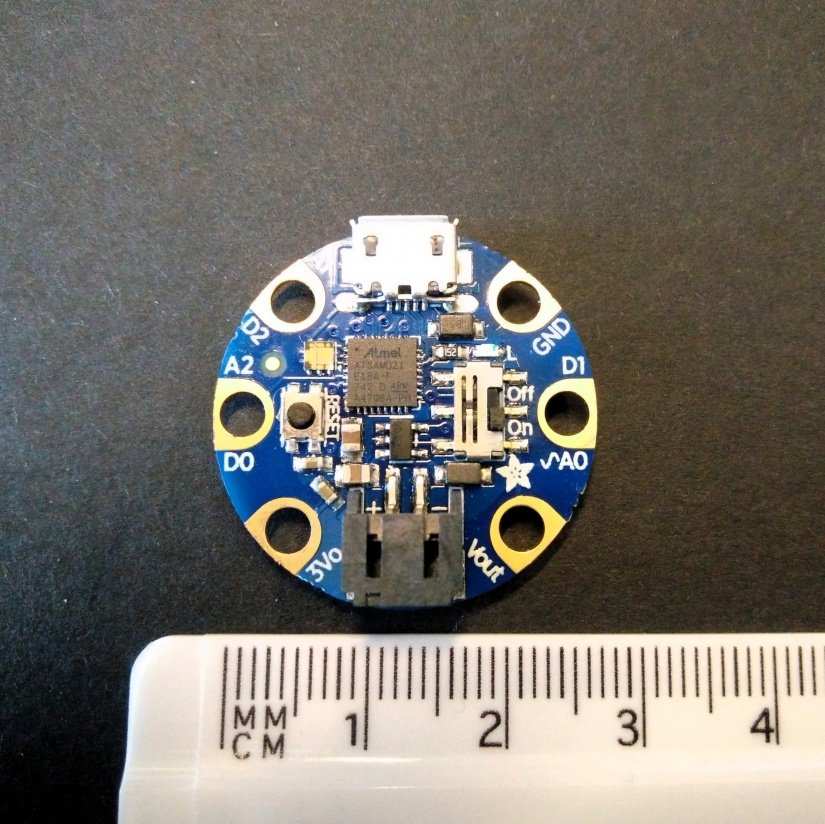

Technical Details
- Same size, form-factor, and pinout as classic Gemma
- ATSAMD21E18 32-bit Cortex M0+
- 256KB Flash - 8x as much as 8 KB on ATtiny85
- 32 KB RAM - 64x as much as 512 bytes on ATtiny85
- 48 MHz 32 bit processor - 6x as fast as ATtiny85 (not even taking into account 32-bit speedups)
- Native USB supported by every OS - can be used in Arduino or CircuitPython as USB serial console, Keyboard/Mouse HID, even a little disk drive for storing Python scripts.
- Can be used with Arduino IDE or CircuitPython
- Built-in RGB DotStar LED (APA102 LED)
- Three big-hole sew-pads can be used for conductive thread or alligator-clips for fast prototyping
During a recent trip to the USA, for PyCon, we received a special PyCon 2018 branded version of the board, but that hardware is identical to the typical Gemma M0.

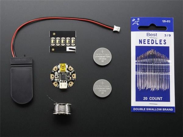
Taking our first steps with Gemma M0 and CircuitPython
The first thing that we need to do is download the Mu editor which has been created by Nicholas Tollervey to work with MicroPython and CircuitPython, and it can be used with PyGame Zero, a simple game creation library for Python, and Mu can also be used with Python 3. To download Mu head over to the following links:
Linux users
Install using the pip package manager for Python 3. Open a terminal and type
sudo apt update
sudo apt python3-pip
sudo pip3 install python-mu
With Mu installed, connect your Gemma M0 to the computer, it will pop up and act like a USB flash drive this is normal. Now open the Mu application.
Taking a quick look at Mu
Mu has been designed as a basic Python editor for those starting on their Python journey. So while it may not have the advanced features of mainstream editors, it does have simplicity and ease of use for new users. At the top of the screen we can see icons to perform Open/Save files. But we can also see a REPL (Read Eval Print Loop, the Python shell interface) and Plotter, used to graphically display data using a chart. We can also zoom in/out of code and change the theme. There is also a built-in code checker, for making sure our code meets the requirements.
Mu can be used with Python 3, PyGame Zero, micro:bit, and Adafruit boards but we need to ensure that we are using the correct mode for the project. To do that we need to click on the mode in the bottom right of the screen and set the mode to Adafruit CircuitPython.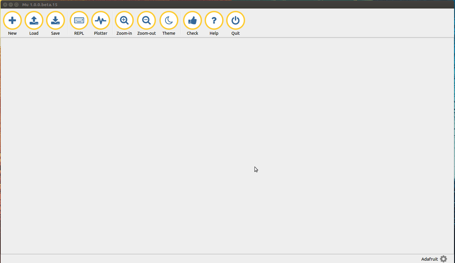
Creating some code
For this brief tutorial, we shall blink the onboard DotStar RGB LED. Three times red, three times green and then three times blue.
So let us start the code for this project by first importing three Python libraries. The first is called board, and this enables us to work with the Gemma M0. The second is adafruit_dotstar and this enables us to use the onboard DotStar LED. The final library is time which we shall use to pace the speed of the colour change.
Create a new file in Mu and add this code.
import board
import adafruit_dotstar
import time
We next create two variables, the first is t and in it we store the duration of how long the DotStar LED will be on and off. In this case we chose 0.1 seconds, but the value can be whatever you wish. The second variable is an object that creates a link to the onboard DotStar LED that we can easily use by calling the name of the object, in this case, pixels. Add the following code to the project.
t = 0.1
pixels = adafruit_dotstar.DotStar(board.APA102_SCK, board.APA102_MOSI, 1)
On to the main body of code, and for this we need to use a while True loop which will run indefinitely the code contained within it.
Add the code to your project
while True:
Inside the loop, and we create three for loops that will blink the DotStar LED three times for red, green and blue. To set the number of times the loop will iterate, we create a range, starting at 0 and stopping before it hits 3. Each time the for loop iterates, the value of i is increased by 1.
Add the code to your project.
for i in range(3):
So now we are in the for loop, writing the code to control the DotStar LED. In this case we will tell the onboard LED to turn red. To do this we use the pixels object and tell it the position of the DotStar LED in the “chain”. Here we only have one LED, and as Gemma M0 starts counting from zero, it is position 0. Then we pass three numbers (64,0,0) which represent the mixture of RED GREEN BLUE that the LED can show. The values range from 0 (off) to 255 (full brightness). In this case we shall set the value to 64 (¼ brightness. To see the colour we need to tell the pixels to show the change.
Add the code to your project.
pixels[0] = (64, 0, 0)
pixels.show()
To make sure we can see the colour, we need to tell the code to pause/sleep for a period of time. In this case we call the time.sleep function and pass it the variable t, which stores the value we earlier put into it (0.1 seconds.)
Add the code to your project.
time.sleep(t)
So the LED will show red, but we want it to “blink” and to do that we need to tell the LED to turn off, and to do this we reuse the code that we have just written but change the (64,0,0) to (0,0,0)
Add the code to your project.
pixels[0] = (0, 0, 0)
pixels.show()
time.sleep(t)
With the code completed for red, we can now copy and paste that code, and edit it for green and blue. All we need to do is change the value of the numbers in the (64,0,0) section to represent the RED, GREEN and BLUE values.
Here is the code for green, add this to your project.
for i in range(3):
  pixels[0] = (0, 64, 0)
  pixels.show()
  time.sleep(t)
  pixels[0] = (0, 0, 0)
  pixels.show()
  time.sleep(t)
And here is the code for blue, add this to your project.
   for i in range(3):
        pixels[0] = (0, 0, 64)
        pixels.show()
        time.sleep(t)
        pixels[0] = (0, 0, 0)
        pixels.show()
        time.sleep(t)
So now that we have all of the code for this project, click on Save and save the project as code.py on your Gemma M0 which will be mounted as a USB flash drive. After a few seconds, the Gemma M0 will reboot and you will see the onboard LED blink to match the pattern that we have created.
So there we have it, a brief and simple project for the Gemma M0 that introduces the workflow of this impressively cheap introduction to CircuitPython.

Les Pounder loves hacking and tinkering with Arduino, Raspberry Pi and new technologies. He passes on his skills and discoveries to Electromaker readers via tutorials and reviews.


Leave your feedback...