


Choosing an Edge AI Computer for Your Mobile Robot
With electronica 2026 now over, D-Robotics' mobile-robot briefing with Fibocom leaves a useful engineering takeaway: choose your computer around the work your robot needs to do. The company outlined three examples, spanning a single-camera mower, X5-based stereo vision and an S100 depth-estimation pipeline. Each gave the cameras and software a different job.
This post-event recap looks at what those examples mean for anyone choosing an edge AI computer for mobile robots. Processing images locally can keep perception onboard, but the computer still has to capture those images, run the right models and deliver useful results to the rest of the robot. Camera support, memory, software and timing all belong on your shopping list.
electronica 2026 took place November 10–13 in Munich, with Fibocom listed at C2.724. This recap draws on D-Robotics' November 4 event briefing and official technical documentation.
Why robot workloads come before peak TOPS
Start by writing down what your robot needs to know. Object detection can identify a person or a garden obstacle. Semantic segmentation labels image regions, such as grass and paving. Depth estimation adds information about distance. Localization estimates where the robot is, while planning chooses a route and motion control turns that plan into movement.
Those jobs need different resources. A detection model may use the AI accelerator while camera handling, navigation and communications consume CPU time and memory. Add a second model for human interaction and you have another task competing for a timely result. The useful question is whether the whole pipeline keeps up with your robot.
The mower example: focused perception for a focused job
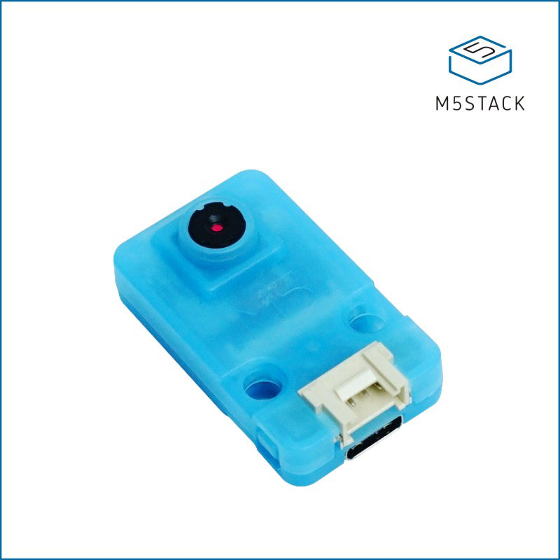
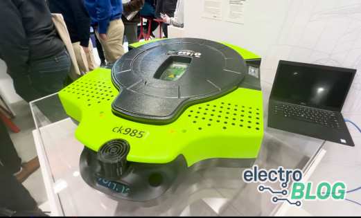
For the joint mower reference design, D-Robotics described a monocular workload built around its Sunrise 3 platform. One camera supplies images for obstacle detection and lawn segmentation. D-Robotics supplies the computing platform, while Fibocom integrates the camera, algorithm board, drive board and the wider perception, navigation and control stack.
The event briefing specified a 5 TOPS platform and a reference design targeting lawns of up to 600 square meters. That area describes the design's intended application. It does not establish mowing time, battery coverage or performance on every lawn.
For your own project, separating the outputs is helpful. A grass mask can inform the navigation software about the working area. An obstacle label can trigger further decisions. You still need a way to estimate position, select a path, control the drive hardware and handle uncertain perception. Recognizing a garden chair is one step in deciding what the mower should do about it.
Sunrise 3 also names a processor family. The official processor documentation distinguishes X3M and X3E configurations. Keep the mower's 5 TOPS example attached to that design instead of assigning one CPU specification to every Sunrise 3 product.
The X5 lesson: stereo depth changes the requirements
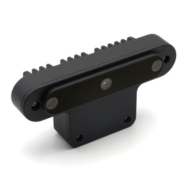
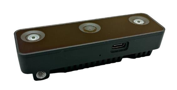
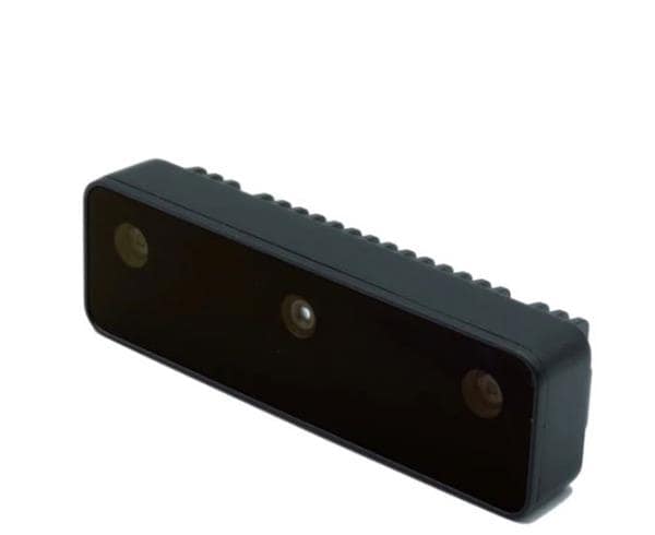
Stereo vision compares corresponding features in left and right images. Their apparent displacement, called disparity, can be converted into depth using the camera geometry. The OpenCV stereo-depth explanation shows why camera separation and focal length matter to that calculation.
A useful stereo system needs synchronized captures, calibration and a supported processing path. Two camera sockets are only part of the picture. For a moving robot, mismatched capture times can complicate correspondence. Texture, lighting and the camera baseline also affect which distances and surfaces produce useful results.
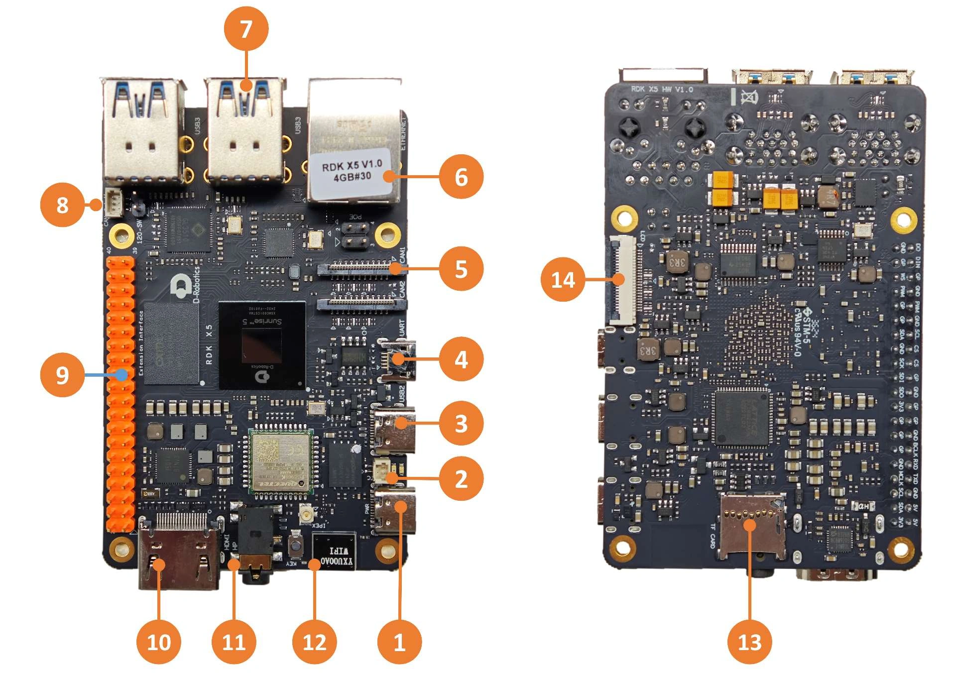
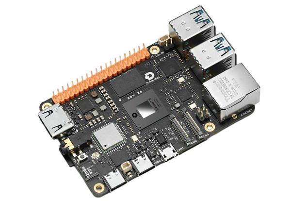
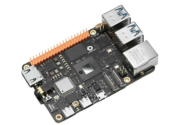
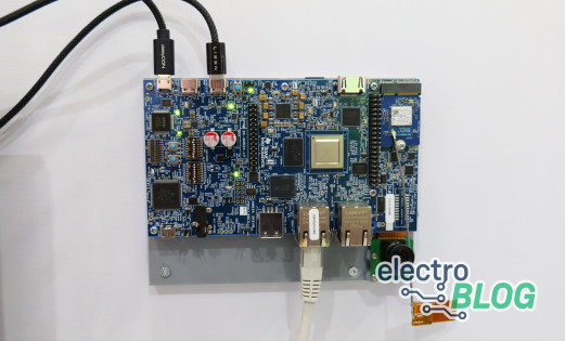
The RDK X5 board provides up to 10 TOPS of BPU acceleration, eight Cortex-A55 CPU cores at 1.5 GHz, 4GB or 8GB of LPDDR4 memory and two four-lane MIPI CSI camera interfaces. Check the X5 hardware manual against the board revision and camera you plan to use.
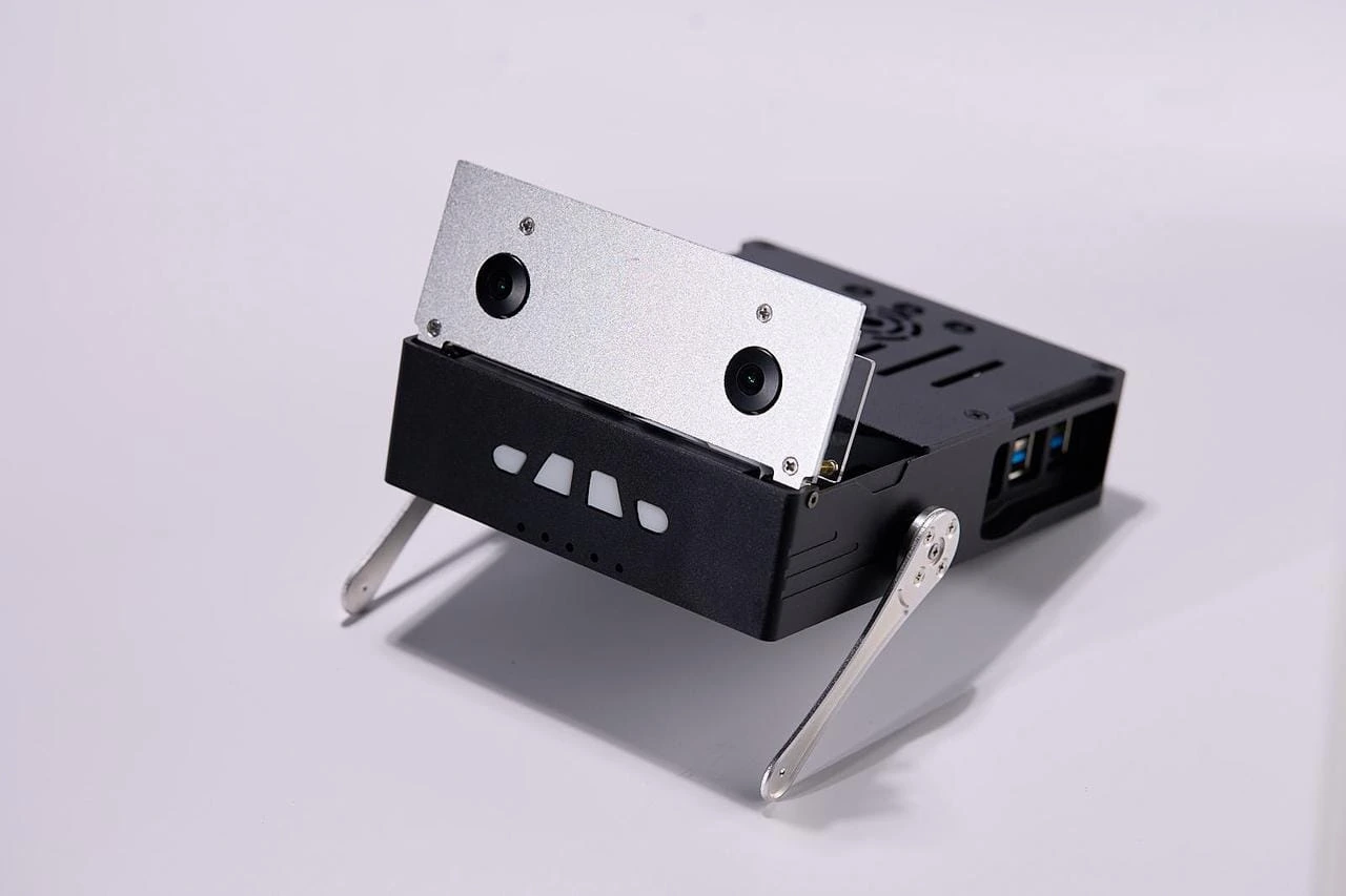
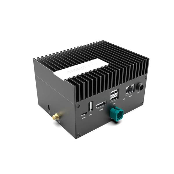
D-Robotics used Magicbox to illustrate X5-based stereo depth and body-keypoint detection in its event briefing. Its own documentation describes integrated cameras, lighting, microphone, speaker and movable supports. Those peripherals belong to Magicbox. A bare X5 board requires its own sensor and mechanical integration.
Stereo is one route to local depth. Monocular depth models and other depth sensors are alternatives. Outdoors, RTK-enabled GNSS, satellite positioning refined with correction data, can complement local perception. It remains a separate system requirement with its own hardware and correction needs.
The S100 takeaway: budget for the complete pipeline
The base RDK S100 combines an 80 TOPS BPU with six Cortex-A78AE CPU cores at 1.5 GHz, four Cortex-R52+ MCU cores and 12GB of LPDDR5 memory. D-Robotics' current S100 hardware manual, in Chinese distinguishes it from the 128 TOPS S100P, which has a 2.0 GHz CPU configuration and 24GB of memory.
Each processor type has a role. The CPU handles general software work. The BPU, or Brain Processing Unit, accelerates compatible neural-network inference. The MCU subsystem provides a separate resource for control-related firmware and communication. Your software design still has to divide and coordinate those jobs, and motor drivers remain part of the wider system.
In its event briefing, D-Robotics reported 640 × 576 input at up to 27 frames per second for its standalone D-Stereo demonstration. That manufacturer-reported figure describes the stereo workload. It does not measure a complete navigation stack running alongside every other model.
For a rover combining depth, detection and navigation, evaluate simultaneous load. Ask what happens to latency and memory use when all required tasks are active. The separate MCU resource also needs a defined interface to the perception and planning software. Its presence alone establishes neither application-level timing guarantees nor a finished robot's safety case.
Comparing the platforms in D-Robotics' event briefing
Use these examples to identify an evaluation candidate. The peak compute figures describe different platforms and do not establish proportional frame rates.
| Platform example | Compute tier | Workload to investigate | Key qualification |
|---|---|---|---|
| Sunrise 3 mower design | 5 TOPS reference design | Monocular detection and lawn segmentation | A partner-integrated reference design using a processor platform |
| RDK X5 / Magicbox | Up to 10 TOPS | Stereo depth and interaction | Magicbox adds integrated peripherals to the X5 platform |
| RDK S100 | 80 TOPS, base variant | Heavier stereo and concurrent robot software | Validate concurrency separately from standalone D-Stereo throughput |
What to check before choosing your robot computer
The practical next step after the show is to turn these examples into a short evaluation plan. A bench prototype with representative inputs will tell you more than another afternoon comparing peak compute figures.
- Define the outputs. Decide whether you need obstacle labels, a navigable-area mask, depth, a location estimate or interaction signals. Set a useful update rate and an acceptable end-to-end delay for each.
- Confirm the sensor path. Record camera count, resolution, frame rate, interfaces, synchronization and calibration. Verify drivers for the exact board and system image.
- Check model and software fit. Map preprocessing, inference, postprocessing, navigation and communications. Confirm supported operators, conversion, quantization and runtime versions before committing to a model.
- Measure the complete load. Run the required tasks together using representative scenes. Record memory use, delayed results and sustained behavior with realistic cooling and power.
- Budget for integration. Include cameras, storage, cooling, power conversion, control interfaces and software maintenance. An adapter rating describes an electrical requirement, while battery runtime needs measured system consumption.
D-Robotics' Resource Center separates platform manuals, TogetheROS.Bot middleware and toolchains. Its official Model Zoo documents supported boards and conversion paths for individual samples. ROS, the Robot Operating System software ecosystem, helps organize robot applications, but installing it does not automatically accelerate every package. An ONNX model likewise needs a compatible deployment path.
What remains useful after electronica
Across these examples, the lasting lesson is to give every required output a sensor, a software path and a timing budget. A focused perception task may justify a simpler platform. Depth and additional models can justify evaluating more compute, provided the complete application benefits from it.
Our earlier RDK S100 launch coverage provides the product's introduction, while our robotics SBC guide offers wider board-selection context.
If X5 fits your evaluation plan, Electromaker lists the 4GB RDK X5, DFR1238 and 8GB RDK X5, DFR1239. Choose memory around your measured workload and check the listing's contents against the sensors and accessories your build requires.
Frequently asked questions
These distinctions are useful when you move from a platform specification to a robot design.
Does more TOPS guarantee faster robot perception?
No. Model compatibility, numerical precision, memory traffic and the surrounding software affect results. Compare the actual pipeline at your required input resolution and concurrent load.
Do mobile robots need stereo cameras?
No. Sensor choice depends on the required outputs. Stereo estimates depth from paired views, while other approaches include monocular models and dedicated depth sensors. Each requires suitable integration and validation.
Are RDK S100 and S100P the same specification?
No. The base S100 is the 80 TOPS, 12GB model with a 1.5 GHz CPU configuration. S100P specifies 128 TOPS, 24GB and a 2.0 GHz CPU configuration. Keep their results and requirements separate.
How do CPU, BPU and MCU resources differ?
The CPU runs general application software, the BPU accelerates supported neural networks, and the MCU subsystem supports control-related firmware. Their presence gives you resources to allocate, with scheduling and communication still part of your design.

Residing on the south coast of England, Rich has spent the last few years building Electomaker.io from the ground up. He is usually found behind a laptop coordinating the rest of the EM team and occasionally finding time to contribute articles to the blog. When not tapping away at a laptop, he can be found either paddleboarding, at the beach, playing golf (badly), or camping with his family.











Leave your feedback...