
Xbox 360 Rf Module Controlled With An Arduino

Made by ViolentLambs / 3D Printing / Games & Gaming
About the project
Using an Arduino UNO R3 board you can Sync, Turn off, and use any Xbox 360 Wireless controller Using 3 types of RF Modules while even using Microsoft's own Xbox 360 Wireless Controller Receiver Driver. If desired you can even 3D print your own case for the device to make it look a better than just having the plain boards.
Project info
Difficulty: Expert
Platforms: Arduino, Microsoft, Windows
Estimated time: 1 day
License: GNU General Public License, version 3 or later (GPL3+)
Items used in this project
Hardware components


Software apps and online services
Hand tools and fabrication machines
Story
NOTE: I will provide links at the bottom of the guide that will give you the same resources I mention through out the guide. That way you won't have to hunt them yourself. Another note this is mainly for PHAT XBOX 360s, The USB part does work for slims but not the Arduino part. The consoles you can get the RF Modules from are the Xenon, Zepher, Falcon, and Jaspers.
I am a huge Xbox 360 enthusiast, I own 4 dev kits (witch games are tested and stressed on) and 1 Halo 3 RGH, and a few other normal retail units. I used to fix them for fun in my free time but I have always had a fascination for the console.
I like to tinker with the hardware here and there but I wanted to try an odd project people around 2012 used to try out themselves. The Xbox 360 has some very unique designs to its hardware and one of the them is its Controller RF Module.
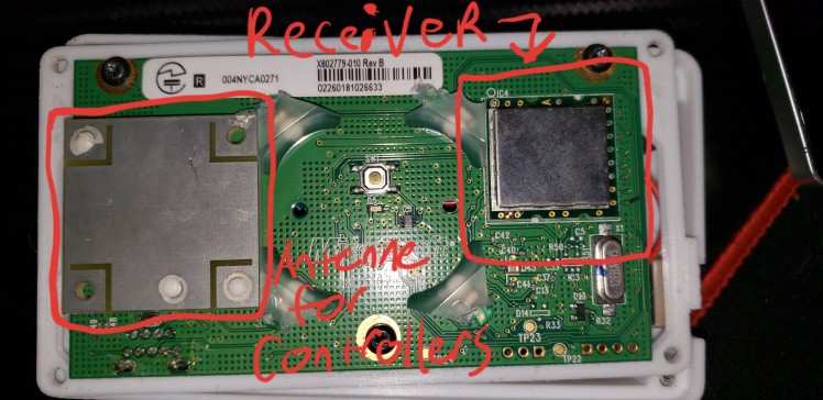
I need to explain a bit about how these work so you get an idea of what the Arduino is actually doing in the circuit. The Module has a bit of retro tech and new tech all in one when its busy working away. One side is the RF module for the controllers and the other is the serial controller on it that receives commands/sends controller data to the Xbox 360.
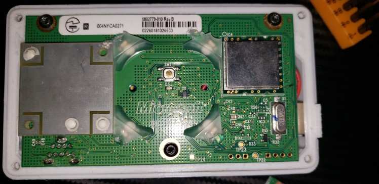
Here is a couple photos of what to expect these to look like when you get one. These may differ slightly depending on what board your trying this with. The board I used and actually recommend is the REV B board but the REV H RF01/RF02 can work but I had some problems with these boards witch I will explain later.
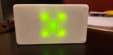
Here above is the front of my RF board. The Covers on the ROL (Ring of lights) isn't needed it just made the lights look better when my front cover is on.
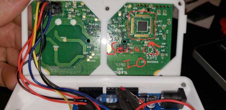
The back of these can also vary a little bit but I circled the serial controller but you don't actually have to worry about that part specifically. Its interfacing with it is where the fun is.
Now that I have shown you what my board looks like, I can explain in detail how these work. So on the front of the board the RF module actually works on USB. Yes basic USB 2.0! This is pretty neat here because if you were to hook up 4 wires for the USB solder pads, your computer will recognize it as an unknown device but if you install the wireless receiver driver and point it to the unknown device it starts working right away. When in this state the board wont respond to any inputs, no lights, no response from the button, etc etc..
But how would I use a controller with it if it doesn't respond in this state? Well that is the catch. In order to use a controller you would need to first put the RF module into an Xbox 360, boot the console, then sync the controller and then plug the module back into your PC. You can turn the controller off and on by removing the batteries briefly but when you power it back on it will connect right away. Still though the board wont respond to inputs and that is where the Arduino comes in to play.
This is honestly my favorite part of how this thing works. Modders have found out that you can actually send data to the RF module and have it follow commands however it is NOT possible to receive data from the RF board such as controller battery status, or use it to control robots and stuff. I want to explain this a little bit, The Arduino and the RF module are technically two entirely separate things that have different tasks. When you are using the device to play games the RF portion works entirely on its own.
Now say you are done or want to switch controllers. Here is what happens, you press the button on the RF board and it begins the sync animation like on a real Xbox 360 and at the same time you press the sync button on your controller and they bind after a few seconds. If you want to turn your controller off you simply hold the button for 4 seconds and release, the controller turns right off. The Arduino pretends to be an Xbox 360 and the RF Module simply obeys the commands.
The start up process is also interesting as well because the RF board actually has a little boot process of its own that it needs the Xbox 360 for. When you power the Arduino and the RF board at the same time the Arduino sends the "Initialize LED" command, but nothing visually happens but right after this the Arduino sends another command "BootAnim" witch is the normal Xbox 360 ROL start up sequence, the final step is to set the "PWR LED" witch makes it a steady green. This is to show that the board is powered on and ready. These steps are important regardless if you use the code I will provide (credit to the original writer of it at the end of the project) or if you write your own. Also the Despite the RF module being its own device during the Xbox 360 boot up process the Xbox 360 actually starts the communication with the module but after that its mainly the RF module sending data to the Xbox 360.
The serial side relies on a clock frequency that is either HIGH or LOW. I was Unable to get a proper formal reading on the actual clock frequency but it should be around 330hz HIGH or 30hz LOW. Your Arduino can see this but figuring this out is another project witch allows me to interface directly with the RF board over a USB to SERIAL adapter that when I can get it working properly I will do a write up on that. However I will link to a page that a user who goes by "Robot9706" made his own set up to manually control an RF Module via USB to serial directly without the Arduino. It is how I was able to test the clock frequency but unfortunately I could only do that as I was unable to get the RF board to respond to inputs but this could be resolved by using a REV B board since I only tried it with RF01 and RF02 Boards.
Here is the thread where he explains how he set it up and he posted a link with a folder that has all the tools and files for you to check out and try it yourself. I only used it for testing but I want to make a functional one as well. Link: https://www.se7ensins.com/forums/threads/how-to-make-a-homemade-xbox-360-controller-wireless-receiver-for-pc.668839/page-14#post-9103564
To figure out what commands you can send to an Xbox 360 RF Module I will link a web page where a user named "Peterbjornx" wrote a wiki page showing how the data works with the serial Micro-Controller. I will also borrow the diagrams for the USB pinout and the pin numbers from his wiki page for the assembly portion of this guide.
Link: https://tkkrlab.nl/wiki/XBOX_360_RF_Module
That is about it for how it works, the code itself will reveal more but lets get to building the whole thing.
The 3 types of RF modules I attempted this project with are the REV H RF01/RF02 and REV B boards. The odd thing for me was a lot of people were able to get the REV H boards working but I could not, However for others the REV B was the difficult one to work with. You may have to try all 3 to get the right one that works off the bat as its not the code that is the problem its the boards themselves they can be really odd sometimes. Here is some pictures of the REV H RF01, RF02 and the REV B:
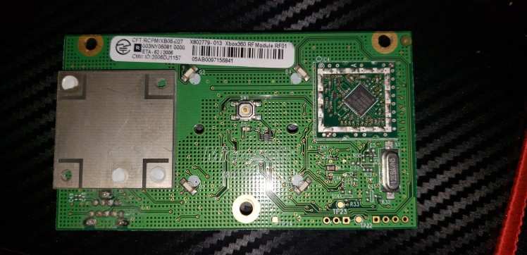

The backs of these wont matter much except where we will be soldering witch I will get to here soon.
Next lets take a look at how this will be wired up, the wiring is pretty simple but I do have to stress that its really important that the voltage is 3.3v going into the RF module as not only would it not work correctly going higher than this could damage the RF module and I did have some accidental casualties with this project, luckily RF boards are really cheap.
Here is a diagram of the pinout of where the USB wires go and same with the Arduino's:

The parts of the Arduino we will be using would be pin 2,3,and 4 on the PWM side, 3.3v pin, and the ground (witch also needs to be connected to the USB ground as well). I made a diagram showing where all the wires go.
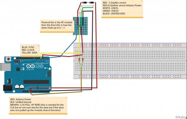
This is as simple as i can make the diagram but one thing I do want to say is that I tried this on two Arduino Leonardos and for whatever reason they could not see when the clock would change from high to low. This actually stumped me for a long time since I don't understand what it is about the UNO R3 that can see it but the Leonardo cannot. When the Xbox 360 Module starts up the CLK is high but when its done starting up it switches to low waiting for the next command. I did however get the Leonardo to actually start up the board and that is all i was able to get them to do.
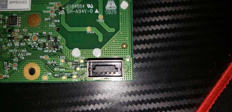
For testing purposes I would strongly recommend harvesting the socket the RF module sits in from a dead Xbox 360 motherboard ( This is where a Hot Air Station would come in handy) because getting to the pins to solder to are a pain. You could solder test leads to the front but due to how heat resistant the solder joints are on the front and how close they are together make it rather difficult to work with and depending on what solder you use, your beads may want to stick together quite a bit. Here is the photo of the male side of the socket. See the metal shield? this is and obstacle. I actually just used needle nose pliers to remove it but you could try de-soldering it but it tends to absorb the heat and dissipate rather quickly but with patients and wigging gently at each of the solder points around the shield it will come off. Then once the shield is off you can gently pull the black pin divider off and have full access to the pins. In my build I did exactly this to make it as compact as possible for the 3D printed shell but you don't have to do this if you do not want to. 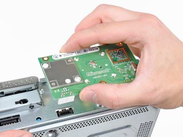
I have borrowed a photo from iFix it for showing the front of the xbox 360 specifically the female RF socket so you know that it looks like. Using this socket will allow you to switch RF boards at will the only thing that makes it a little off putting is that each time you change the RF module you will have to set up the windows driver again. Do not install again, just go under device manager and point the driver back to the RF receiver.
Here is the link for the microsoft driver and I will post screen shots of how to set it up because it doesn't automatically work out of the box after installing: https://www.microsoft.com/accessories/en-my/d/xbox-360-wireless-controller-for-windows
Install this like you would any other driver software, Then plug in your Xbox 360 RF module to your computers USB port. In device manager you will see an Unknown device is listed there.
Right-click on the device then click "Update driver":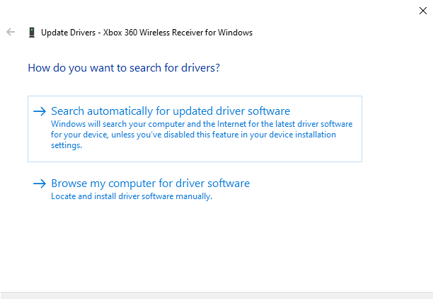
Then click "Browse my computer for driver software":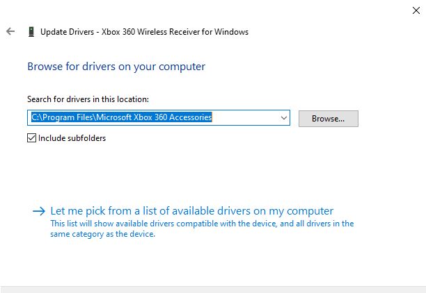
Then Click "Let me pick from a list of drivers on your computer". Now you may have dig through an extensive list there but there will be a folder called something along the lines of "Xbox 360 wireless accessories". Here there will be quite a few options but the specific one in this list you want is the "Xbox 360 Wireless Receiver for Windows Version 10.0.18362.1". After confirming this device manager will refresh and your receiver will show up at the bottom of the list ready to go. If you bound a controller to this prior to messing with it you can fire up any games that support the Xbox 360 controller and test to see if its working correctly. 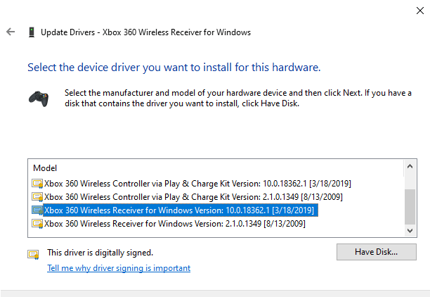
If the module is working correctly then now you just need to get your Arduino ready. Simply plug the Arduino into the USB port on your computer, open Arduino IDE and select your board, COM port and then copy and paste the code that is in the code section of the project. The code does not need to be modified unless you plan on editing it for yourself or maybe trying to get it to work on different versions of Arduino boards.
Once flashed connect your Arduino leads to the board following the diagram above showing the whole layout. Then power cycle both the arduino and the RF module and if the assembly is done correctly the board should initialize and when its done starting up press the sync button (witch used to be the power button) and it should start the sync animation, if that is working then congrats! Your almost done here.
Next is the enclosure. this is up to you on how you want to approach this but you can use the same design I used for mine witch may or may not need tweaked to use with more modern 3D printer software. Here is " Martin Ballantyne's" design and here is how his turned out for him since his pictures are cleaner and clearer than mine are. It fits the UNO R3 perfectly fine: 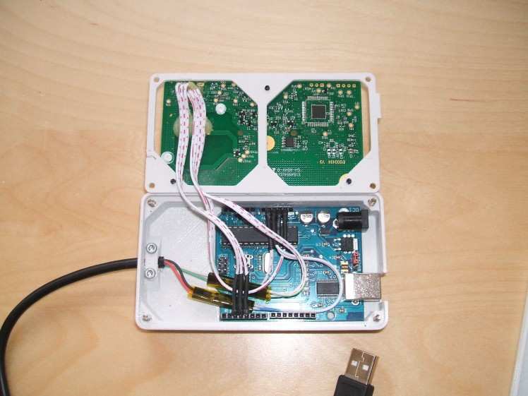
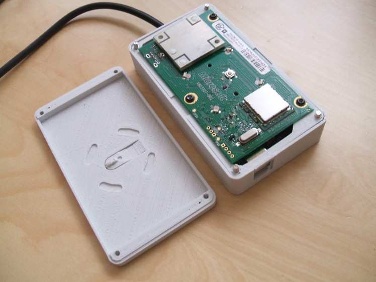
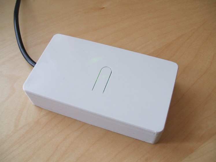
Here is where you can download his Controller receiver folder that contains his code modifications, case design and the same photos I used here.
Link: https://www.mediafire.com/file/z6b5k1n3s2n3u41/XboxControllerReceiver.zip/file
Here is his code modifications. Simply Copy and paste this into Arduino IDE and upload to your Arduino and that is it.
- /* Arduino code to communicate with xbox 360 RF module.
- Original work by (yaywoop)
- Additional ideas from Alexander Martinez
- Modified by dilandou (www.dilandou.com, http://www.diru.org/wordpress)
- Controller turn off added by Martin Ballantyne using research from http://tkkrlab.nl/wiki/XBOX_360_RF_Module
- First sends LED initialisation code followed by LED startup animation code, then sleeps until a button press for sync command.
- If the sync button is held down and released after 1000ms the connected controllers will be turned off. Otherwise the sync command will initiate.
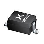
- RF module must be powered with 3.3V, two diodes in series with USB 5v will do. Connect the USB wires to a host computer, and the data and serial wires to Arduino.
- of course, make sure to have a common ground */
- #include
- #define sync_pin 2 //power button repurposed for sync button (pin 5 on the module)
- #define data_pin 3 //data line (pin 6 on the module)
- #define clock_pin 4 //clock line (pin 7 on module)
- int led_cmd[10] = {0,0,1,0,0,0,0,1,0,0}; //Activates/initialises the LEDs, leaving the center LED lit.
- int led_timer_red_1[10] = {0,0,1,0,1,1,1,0,0,0}; //Set quadrant 1 to red
- int led_timer_red_2[10] = {0,0,1,0,1,1,1,1,0,0}; //Set quadrant 1 and 2 to red
- int led_timer_red_3[10] = {0,0,1,0,1,1,1,1,0,1}; //Set quadrant 1, 2 and 4 to red
- int led_timer_red_4[10] = {0,0,1,0,1,1,1,1,1,1}; //Set quadrant 1, 2, 3 and 4 to red
- int led_red_off[10] = {0,0,1,0,1,1,0,0,0,0}; //Set quadrant 1, 2, 3 and 4 to off
- int anim_cmd[10] = {0,0,1,0,0,0,0,1,0,1}; //Makes the startup animation on the ring of light.
- int sync_cmd[10] = {0,0,0,0,0,0,0,1,0,0}; //Initiates the sync process.
- int turn_off_cmd[10] = {0,0,0,0,0,0,1,0,0,1}; //Turns off the connected controllers.
- volatile boolean sync_pressed = 0;
- int sync_hold_time = 0;
- boolean turn_off_controllers = false;
- void sendData(int command[])
- {
- pinMode(data_pin, OUTPUT);
- digitalWrite(data_pin, LOW); //start sending data.
- int previous_clock = 1;
- for(int i = 0; i = 1000)
- {
- sendData(led_timer_red_4);
- }
- else if(held_time >= 750)
- {
- sendData(led_timer_red_3);
- }
- else if(held_time >= 500)
- {
- sendData(led_timer_red_2);
- }
- else if(held_time >= 250)
- {
- sendData(led_timer_red_1);
- }
- else
- {
- sendData(led_red_off);
- }
- }
- void initLEDs()
- {
- sendData(led_cmd);
- sendData(anim_cmd);
- }
- void wakeUp()
- {
- sync_pressed = 1;
- }
- void sleepNow()
- {
- set_sleep_mode(SLEEP_MODE_PWR_DOWN); // set sleep mode
- sleep_enable(); //enable sleep bit
- attachInterrupt(0, wakeUp, LOW);
- sleep_mode();
- sleep_disable(); //disable sleep bit
- detachInterrupt(0); // disables interrupt 0 on pin 2
- }
- void setup()
- {
- Serial.begin(9600);
- pinMode(sync_pin, INPUT);
- digitalWrite(sync_pin,HIGH);
- pinMode(data_pin, INPUT);
- pinMode(clock_pin, INPUT);
- delay(2000);
- initLEDs();
- }
- void loop()
- {
- // Only sleep if the sync button is not held down
- if(!sync_pressed)
- {
- sleepNow();
- }
- delay(200);
- if(sync_pressed)
- {
- Serial.print(“Sync held time (ms): “);
- Serial.println(sync_hold_time, DEC);
- setHeldLEDs(sync_hold_time);
- // Count 1000ms, if elapsed the user wants to turn off their controllers
- if(sync_hold_time >= 1000)
- {
- turn_off_controllers = true;
- sync_hold_time = 1000;
- }
- // Initiate the user’s action when they release the sync button
- if (digitalRead(sync_pin))
- {
- setHeldLEDs(0);
- if(turn_off_controllers)
- {
- Serial.println(“Turning off controllers.”);
- sendData(turn_off_cmd);
- turn_off_controllers = false;
- }
- else
- {
- Serial.println(“Syncing controllers.”);
- sendData(sync_cmd);
- }
- // Action complete, reset hold time and button state
- sync_hold_time = 0;
- sync_pressed = false;
- }
- else
- {
- sync_hold_time += 200;
- }
- }
- }
Here is a list of my sources where I gathered all this information from all in one place anyone can check it all out too:
Link one:(the original Project source code by the user " Dil " : https://dilisilib.wordpress.com/hacking/xbox-360-rf-module-arduino/ (you can also see other users posts talking about using different types of Arduinos and they code they used and one person even used Raspberry Pi as well.)
Link Two: Microsoft Xbox 360 Wireless Controller Driver (Even though it says Windows 7 is the highest supported driver it works perfectly fine for me in Windows 10): https://www.microsoft.com/accessories/en-my/d/xbox-360-wireless-controller-for-windows
Link Three: Martins folder containing the code and the 3D printer files (these may need converted for newer 3D printers): https://www.mediafire.com/file/z6b5k1n3s2n3u41/XboxControllerReceiver.zip/file
Link Four: "Robot9706's" thread on using the USB to Serial adapter to manually control an RF module: https://www.se7ensins.com/forums/threads/how-to-make-a-homemade-xbox-360-controller-wireless-receiver-for-pc.668839/page-14#post-9103564
Schematics, diagrams and documents
CAD, enclosures and custom parts
Code
Credits
ViolentLambs
I'm just a guy who likes to build small projects in my free time and I like to share with the communities what I have made!
Related products


Leave your feedback...