

Water Cooling Wearable

Made by electrouser881 / Environmental Sensing / Health / Home Automation / Sensors / Wearables
About the project
Version 1 of my temperature controlling wearable.
Project info
Difficulty: Difficult
Estimated time: 5 hours
Items used in this project
Hardware components


View all
Story
Some of you may remember my 5 Minute USB Wrist Cooler, a project used to cool my body down without having to sweat. The downside of this, was that it only lasted about 5 minutes. Thanks to a sponsorship from DFRobot, I was able to extend this time to about three hours and cool down more than just my left wrist.
This project used cools water in an aluminum block using a Peltier Module and a PC Fan, then pushes it throughout some tubing using a DC pump. These are powered with rechargeable li-ion batteries that can be charged with a back-mounted solar panel. The tubing of the Liquid Cooling Wearable is meant to be worn under a tightfitting undershirt to maximize contact with the skin. Using a Dfrduino, I even added an automatic temperature controller that uses a DHT22 to activate the wearable.
Pictures with me wearing it coming soon(version 2), but for now, Let's get started!
Step 1: Tools and Materials
For this project you will need (they all open in new tabs automatically):
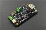
12VDC Sunflower Solar Charge Controller
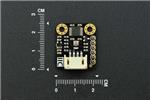
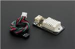
DHT-22 Temperature and Humidity Sensor
Step 2: Assembling the Cooling Device
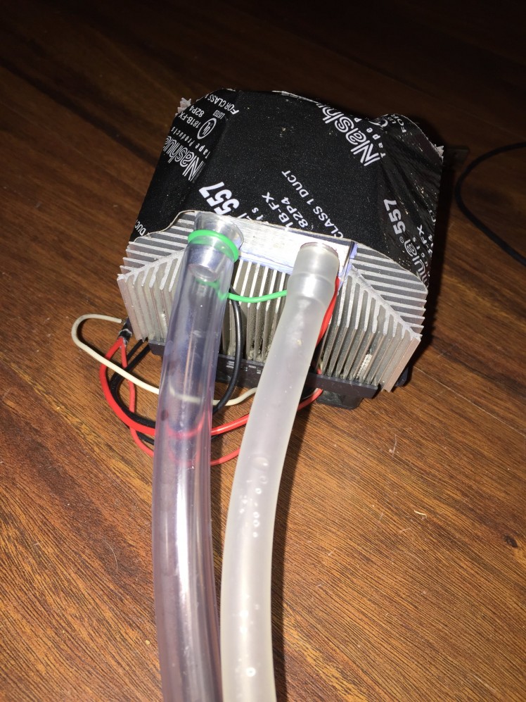
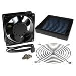
First, cover your aluminum cooling block in thermal pads, thermal paste, or thermal grease. Don't put too much as it will hamper the heat transfer process. Now stick your Peltier module on it with the labelled side not facing you.
Second, make sure your heatsink and fan combo works. Screw the fan onto the heatsink and turn it on. The bottom part of the heat sink should be a little bit cooler than the ambient, but not too much as the fan is just blowing air right now. If it works, go to the next step.
Last, coat the other side of the Peltier and stick it on the heat sink. Now, your aluminum block will cool the water that will flow through it and the fan attached to the Peltier will get rid of excess heat. I used some duct tape to make a stronger mechanical bond but that isn't necessary. Now we are ready to connect it to the pump and tank with our tubing. Connect the two wires into one to make wiring easier. These are 12v high current drawing components, so be sure to use a large wire gauge.
Step 3: Pumps and Plumbing
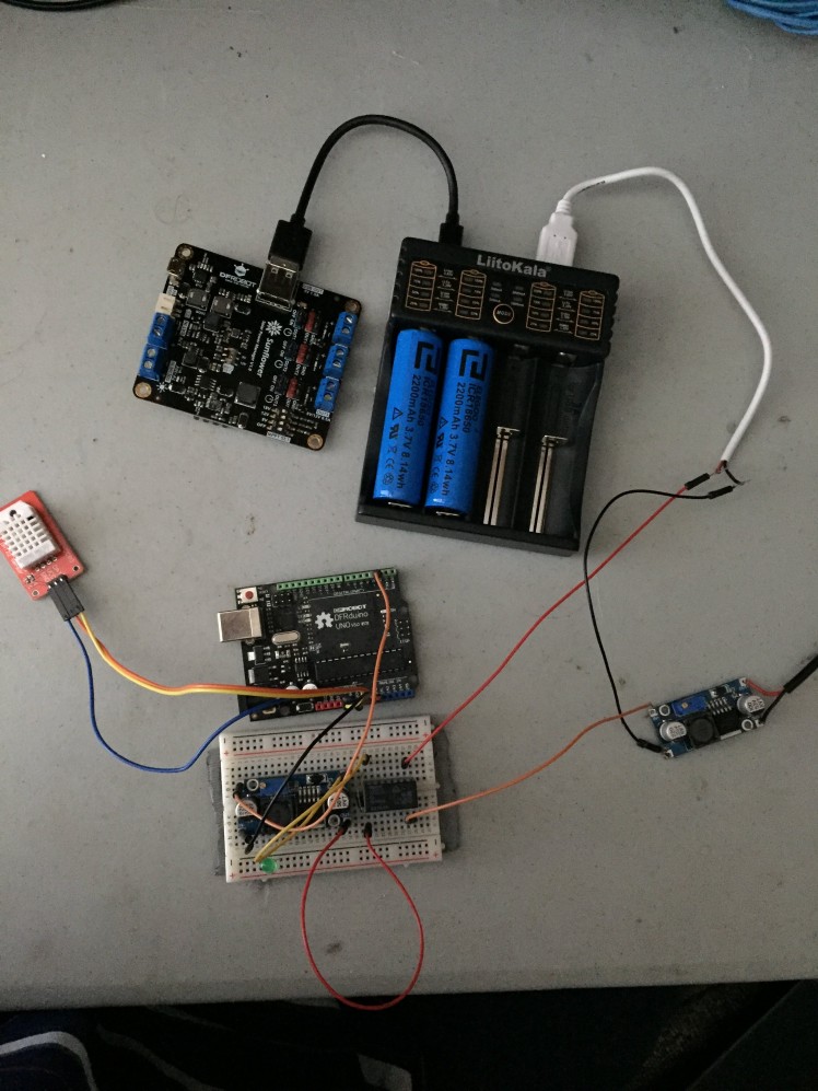
Pump Electronics
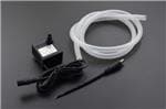
The pump comes with a standard plug with exposed wires at the end. Solder these wires to a boost converter as our default voltage of 5 volts won't cut it. We'll be using the booster to get 11vdc from our batteries. On the other side, solder a USB cable. Use the potentiometer to set the output voltage to about 11 volts. The pump is rate for 6v-12v, but I decided to stay safe with 11 and also not burden the boost converter too much as it has no extra heat sink. Test your electronics by connecting the pump and submerging it in water. It should be on.
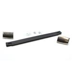
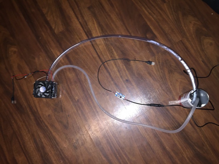
Tank and Tubing
To store the water for the system, I used a 2" aluminum can. I tried using 2" PVC pipe, but it was too thick for the pump to fit, requiring me to either file the pump, or shave the inside of the whole PVC pipe. I'll update the project to PVC in the next version. Connect the tubing that came with your pump to it, then to the aluminum block. Using some of the vinyl tubing, connect the other side of the aluminum cooling block and tape it to the inside of your water tank (aluminum can in this case). Once this is done, test your pump out inside the tank by filling it up and turning it on. It is also important to do this to check for leaks.
Step 4: Cooling, Code, and Circuitry
Cooling
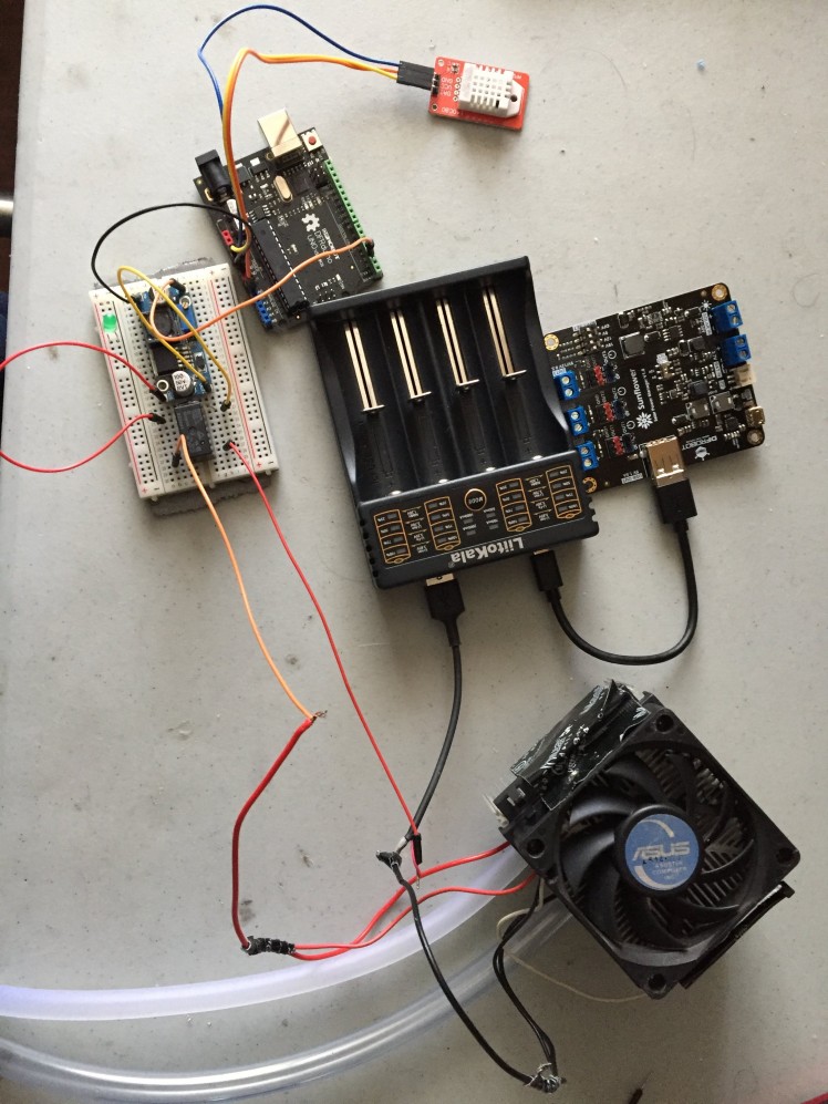
Using the Dfrduino, you will need to set a minimum temperature index to activate the Peltier and fan cooling combo. We will do this using the inexpensive, but reliable DHT22 temperature and humidity sensor. I'll be using Analog Pin 0 for the data wire, but you can use another if you'd like. Connect VCC and GND to their respective points on the Dfrduino. This will give us information, but not do anything by itself. To actually turn on(and off) the cooling device we built, we need to set up a relay to electromechanically switch the power on and off. I only have 12v relays, and Arduinos output a max of 5v, so I am using a boost converter to step up the voltage from 5v to 12v for it to activate.
Circuitry
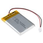
The aforementioned circuit is powered through solar power using DFRobot's Sunflower Solar Controller. It takes input from my 12v (5W) photovoltaic panel and regulates it into a usable voltage and current. The Smart Multifunctional Charger also by DFRobot uses this to charge the batteries shown in the image, but also doubles as a powerbank to provide energy for the cooling device to function.
Code
Copy paste the code into your Dfrduino so that the fan(and by extension the Peltier module) turn on if it is hot enough. I used example temperatures, so be sure to change those.
Step 5: How It Works
Like in my other Peltier builds, the thermoelectric cooler gets a set voltage (12 volts in this case) and pumps heat from one side of the module to the other. This drastically cools one side of the ceramic square and heats the other side. To prevent from damaging our component through heat backpropagation, we must use active cooling in the form of a large heatsink and fan. This project uses the cool side to remove heat from water traveling through an aluminum block and then utilizes a dc pump to push this throughout the user's body using vinyl tubing. To increase contact with skin, a tight shirt is worn over it.
To save a bit of energy from the most energy intensive parts of this, the fan and Peltier are turned off if it gets too cold (you go indoors for example). The Dfrduino is connected to a boost converter to turn on a relay and power the cooling assembly if and only if the data from the DHT22 temp and humidity sensor warrants it.
Step 6: Special Thanks to DFRobot
This was a pretty big project, so I'm glad to have been sponsored by DFRobot. Great product quality and fast shipping as always. Check out their store here.
Code
Credits
Related products


Leave your feedback...