

Visuino: Infrared Remote Controlled Arduino Smart Car Robot

About the project
Program Infrared Remote Controlled Arduino Smart Car Robot With Visuino - Quick and Easy!
Project info
Difficulty: Easy
Estimated time: 1 hour
License: GNU General Public License, version 3 or later (GPL3+)
Items used in this project

Software apps and online services
Story
Recently I received a Smart Car Robot Kit donated by Elegoo for the Visuino development, and I already posted a Tutorial on how to assemble the Kit.
Here I will show you how easy it is to program the Robot with Visuino so you can control it with Infrared Remote.
Step 1: Components
1 / 3 • Picture 1

Picture 1

Picture 2

Picture 3
One assembled Elegoo Smart Car Robot car and the Infrared Remote included in the kit (Picture 1). Pictures 2, and 3 show the unassembled kit.
Here is a Tutorial on how to assemble the robot.
Step 2: Start Visuino, and add Motor Driver Bridge component

To start programming the Arduino, you will need to have the Arduino IDE installed from here: http://www.arduino.cc/.
Make sure that you install 1.6.7 or higher, otherwise this tutorial will not work!
The Visuino: https://www.visuino.com also needs to be installed.
- Start Visuino as shown in the Picture
- Type "motor" in the Filter box of the Component Toolbox then select the "Dual DC Motor Driver 3 Pin Bridge(L298N)" component (Picture), and drop it in the design area.
1 / 6 • Picture 1

Picture 1

Picture 2

Picture 3

Picture 4

Picture 5

Picture 6
- Connect the "Forward" output pin of the "Motors[ 0 ]" channel of the DualMotorDriver1 component to the "Digital" input pin of "Digital[ 7 ]" channel of the Arduino component (Picture 1)
- Connect the "Reverse" output pin of the "Motors[ 0 ]" channel of the DualMotorDriver1 component to the "Digital" input pin of "Digital[ 6 ]" channel of the Arduino component (Picture 2)
- Connect the "Speed" output pin of the "Motors[ 0 ]" channel of the DualMotorDriver1 component to the "Analog" input pin of "Digital[ 5 ]" channel of the Arduino component (Picture 5)
- Connect the "Forward" output pin of the "Motors[ 1 ]" channel of the DualMotorDriver1 component to the "Digital" input pin of "Digital[ 8 ]" channel of the Arduino component (Picture 1)
- Connect the "Reverse" output pin of the "Motors[ 1 ]" channel of the DualMotorDriver1 component to the "Digital" input pin of "Digital[ 9 ]" channel of the Arduino component (Picture 2)
- Connect the "Speed" output pin of the "Motors[ 1 ]" channel of the DualMotorDriver1 component to the "Analog" input pin of "Digital[ 10 ]" channel of the Arduino component (Picture 5)
1 / 5 • Picture 1

Picture 1

Picture 2

Picture 3

Picture 4

Picture 5
You can control the motor speeds directly, however if you suddenly change the motor from stopped to full speed, or from full speed to stop, this will make the robot movements "jumpy", and may lead to wheels easily detaching from the robot. It is better to speed up and slow down the motors gradually using a ramp. Visuino includes "Ramp To Value" components designed for such purpose.
- Type "ramp" in the Filter box of the Component Toolbox then select the "Ramp To Value" component (Picture 1), and drop 2 of them in the design area
- Select the 2 "Ramp To Value" components (Picture 2)
- In the Object Inspector, set the value of the "Initial Value" property to "0.5" (Picture 2) - this specifies that the motors will initially be off
- In the Object Inspector, set the value of the "Slope" property to "2" (Picture 3) - this will specify how fast the motors will ramp up and down
- Connect the "Out" output pin of the RampToValue1 component to the "In" input pin of the "Motors[ 0 ]" channel of the DualMotorDriver1 component (Picture 4)
- Connect the "Out" output pin of the RampToValue2 component to the "In" input pin of the "Motors[ 1 ]" channel of the DualMotorDriver1 component (Picture 5)
1 / 6 • Picture 1

Picture 1

Picture 2

Picture 3

Picture 4

Picture 5

Picture 6
To control the motor speeds for the 4 commands from the remote (Forward, Backward, Left, and Right), and the Stop, we can use "Analog Value" component for each motor with value 0.5 - Stop, and 4 "Set Value State" elements specifying the motor speeds for the 4 commands.
- Type "analog value" in the Filter box of the Component Toolbox then select the "Analog Value" component (Picture 1), and drop it in the design area
- In the Object Inspector set the value of the "Value" property of the AnalogValue1 component to "0.5" (Picture 2) - this will make sure the motor is off by default
- Click on the "Tools" button of the AnalogValue1 component to open the "Elements" dialog (Picture 3)
- In the "Elements" editor select the "Set Value State" in the right window, and clicking on the "+" button 4 times (Picture 4) to add 4 of them
- In the Elements Editor select the "Set Value State1" (Picture 5)
- In the Object Inspector set the value of the "Value" property of the element to "1" (Picture 2) - this will specify the motor to rotate forward
- In the Elements Editor select the "Set Value State2" (Picture 6)
- In the Object Inspector set the value of the "Value" property of the element to "1" (Picture 3)
- Leave the other 2 Elements unchanged. The value of the "Value" property for them will be "0" - this will specify the motor to rotate backward
- Close the "Elements" editor
1 / 6 • Picture 1

Picture 1

Picture 2

Picture 3

Picture 4

Picture 5

Picture 6
- Type "analog value" in the Filter box of the Component Toolbox then select the "Analog Value" component (Picture 1), and drop it in the design area
- In the Object Inspector set the value of the "Value" property of the AnalogValue1 component to "0.5" (Picture 2)
- Click on the "Tools" button of the AnalogValue1 component to open the "Elements" dialog (Picture 3)
- In the "Elements" editor select the "Set Value State" in the right window, and clicking on the "+" button 4 times (Picture 4) to add 4 of them
- In the Elements Editor select the "Set Value State1" (Picture 5)
- In the Object Inspector set the value of the "Value" property of the element to "1" (Picture 2)
- In the Elements Editor select the "Set Value State4" (Picture 6)
- In the Object Inspector set the value of the "Value" property of the element to "1" (Picture 3)
- Leave the other 2 Elements unchanged
- Close the "Elements" editor
1 / 2 • Picture 1

Picture 1

Picture 2
- Connect the "Out" output pin of the AnalogValue1 component to the "In" input pin of the RampToValue1 component (Picture 1)
- Connect the "Out" output pin of the AnalogValue2 component to the "In" input pin of the RampToValue2 component (Picture 2)
1 / 3 • Picture 1

Picture 1

Picture 2

Picture 3
To decode the infrared commands, we will add Infrared Receiver component. The simplest way to decode a specific command is to add Decode element to the Infrared Receiver Elements: We will add 4 such elements for the 4 commands - Forward, Back, Left and Right.
- Type "infra" in the Filter box of the Component Toolbox then select the "Infrared Receiver" component (Picture 1), and drop it in the design area
- Click on the "Tools" button of the InfraredReceiver1 component to open the "Elements" dialog (Picture 2)
- In the "Elements" editor select the "Decode NEC Command" in the right window, and clicking on the "+" button 4 times (Picture 3) to add 4 of them
1 / 5 • Picture 1

Picture 1

Picture 2

Picture 3

Picture 4

Picture 5
- In the Elements Editor select the 4 Decode NEC Command elements (Picture 1)
- In the Object Inspector set the value of the "Repeat Interval" property of the element to "200" (Picture 1)
- In the Elements Editor select the "Decode NEC Command1" (Picture 2)
- In the Object Inspector set the value of the "Value" property of the element to "16736925" (Picture 2) - This will specify the Infrared button code. You can follow this tutorial to discover the codes for each button of your remote
- In the Elements Editor select the "Decode NEC Command2" (Picture 3)
- In the Object Inspector set the value of the "Value" property of the element to "16761405" (Picture 3)
- In the Elements Editor select the "Decode NEC Command3" (Picture 4)
- In the Object Inspector set the value of the "Value" property of the element to "16754775" (Picture 4)
- In the Elements Editor select the "Decode NEC Command4" (Picture 5)
- In the Object Inspector set the value of the "Value" property of the element to "16720605" (Picture 5)
- Close the "Elements" editor
1 / 4 • Picture 1

Picture 1

Picture 2

Picture 3

Picture 4
- Connect the "Out" output pin of the "Elements.Decode NEC Command1" element of the InfraredReceiver1 component to the "In" input pin of the "Elements.Set Value State1" of the AnalogValue1 component (Picture 1)
- Connect the "Out" output pin of the "Elements.Decode NEC Command1" element of the InfraredReceiver1 component to the "In" input pin of the "Elements.Set Value State1" of the AnalogValue2 component (Picture 2)
- Connect the "Out" output pin of the "Elements.Decode NEC Command2" element of the InfraredReceiver1 component to the "In" input pin of the "Elements.Set Value State2" of the AnalogValue1 component (Picture 3)
- Connect the "Out" output pin of the "Elements.Decode NEC Command2" element of the InfraredReceiver1 component to the "In" input pin of the "Elements.Set Value State2" of the AnalogValue2 component (Picture 4)
1 / 6 • Picture 1

Picture 1

Picture 2

Picture 3

Picture 4

Picture 5

Picture 6
- Connect the "Out" output pin of the "Elements.Decode NEC Command3" element of the InfraredReceiver1 component to the "In" input pin of the "Elements.Set Value State3" of the AnalogValue1 component (Picture 1)
- Connect the "Out" output pin of the "Elements.Decode NEC Command3" element of the InfraredReceiver1 component to the "In" input pin of the "Elements.Set Value State3" of the AnalogValue2 component (Picture 2)
- Connect the "Out" output pin of the "Elements.Decode NEC Command4" element of the InfraredReceiver1 component to the "In" input pin of the "Elements.Set Value State4" of the AnalogValue1 component (Picture 3)
- Connect the "Out" output pin of the "Elements.Decode NEC Command4" element of the InfraredReceiver1 component to the "In" input pin of the "Elements.Set Value State4" of the AnalogValue2 component (Picture 4)
1 / 2 • Picture 1

Picture 1

Picture 2
- In Visuino, Press F9 or click on the button shown on Picture 1 to generate the Arduino code, and open the Arduino IDE
- In the Arduino IDE, click on the Upload button, to compile and upload the code (Picture 2)
If you get compiler error in the Arduino IDE, this means that you are missing the following library:https://github.com/z3t0/Arduino-IRremote
Look at this Tutorial to see how to install it!
Step 13: And play...
Congratulations! You have a full Infrared Remote control over your Smart Car Robot.
If you power up the Smart Car Robot, you can control it by pressing on the Arrow buttons of the Infrared Remote as shown on the Video.
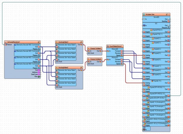
On the Picture you can see the complete Visuino diagram.
Also attached are the Visuino projects, that I created for this Tutorial. You can download and open them in Visuino: https://www.visuino.com
Code
Credits
Related products


Leave your feedback...