






🔥 Touch-controlled Dimmable Retro Light Bulb With Arduino A
About the project
In this tutorial, you will build a touch-controlled dimmable light using a 5V retro light bulb module, a capacitive touch sensor.
Project info
Difficulty: Easy
Platforms: Adafruit, Arduino, Visuino
Estimated time: 1 hour
License: GNU General Public License, version 3 or later (GPL3+)
Items used in this project
Hardware components


Story
In this tutorial, you will build a touch-controlled dimmable light using a 5V retro light bulb module, a capacitive touch sensor, and an Arduino.
The project works as a smooth toggle system:
Touch the sensor once → the bulb slowly fades ON
Touch the sensor again → the bulb slowly fades OFF
The tutorial shows how to connect the touch sensor and the retro light bulb module, and how to configure the logic so the bulb smoothly changes its brightness state with each touch. Instead of switching instantly, the light transitions gradually between OFF and ON.
The retro light bulb provides a warm, vintage-style glow, while the smooth dimming creates a comfortable ambient lighting effect. The touch sensor enables silent and reliable operation, replacing a traditional mechanical switch. The entire setup runs on 5V, making it suitable for common Arduino boards.
This project can be used as a base for ambient lamps, decorative lighting, bedside lights, or interactive electronics projects where soft light transitions are preferred.
In this tutorial, you will learn how to:
- Connect a capacitive touch sensor to an Arduino
- Control a 5V retro light bulb module with analog output
- Implement touch-based toggle behavior with smooth transitions
- Create fade-in and fade-out light effects
- Build a touch-controlled ambient lighting circuit
📥 Download the Visuino project file at the bottom
🎥 Watch the Video!
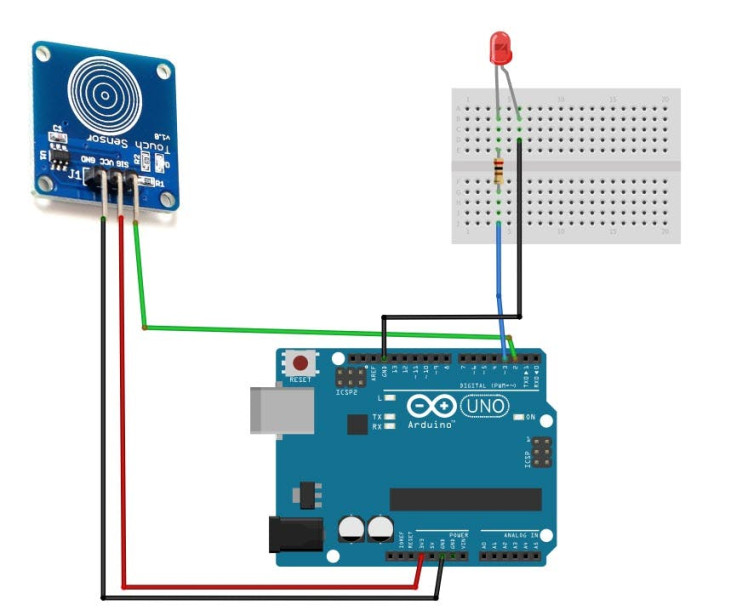
Note: You can use an LED module or another light source instead. Just make sure to use a suitable resistor in series.
Step 1: What You Will Need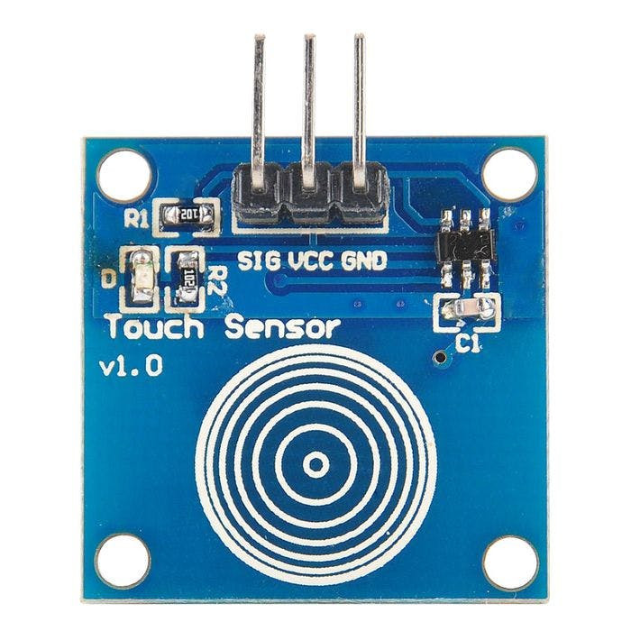
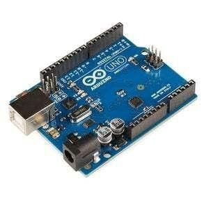
- Arduino (or any other board)
- Capacitive touch sensor module (you can also use the regular button with 1K resistor)
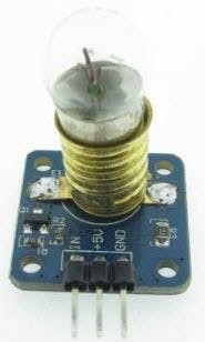
- Retro 5V Light bulb module (E10 Incandescent Lamp Module Bulb Module)
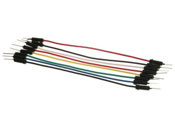
- Jumper wires
- Visuino program: Download Visuino
Note: You can use LED module instead, or any other light, just make sure you use the 1K resistor in series.
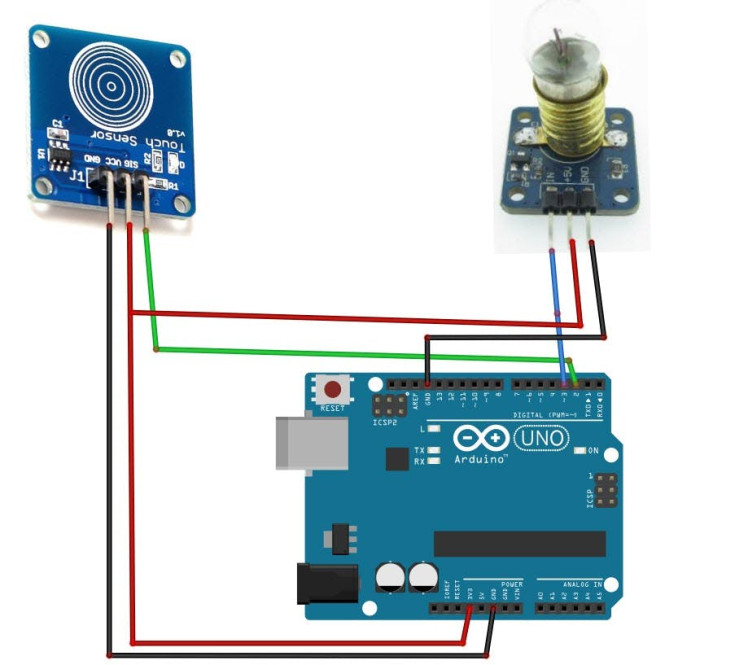
Step 2: The Circuit- Connect Capacitive touch sensor "Signal" pin to Arduino Digital pin[2]
- Connect Capacitive touch sensor "VCC" pin to Arduino pin [5V]
- Connect Capacitive touch sensor "GND" pin to Arduino pin [GND]
- Connect Arduino Digital pin [3] to Retro Light pin [In]
- Connect Arduino 5V pin to Retro Light pin [VCC]
- Connect Arduino GND pin to Retro Light pin [GND ]
1 / 2
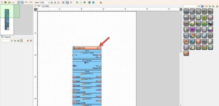
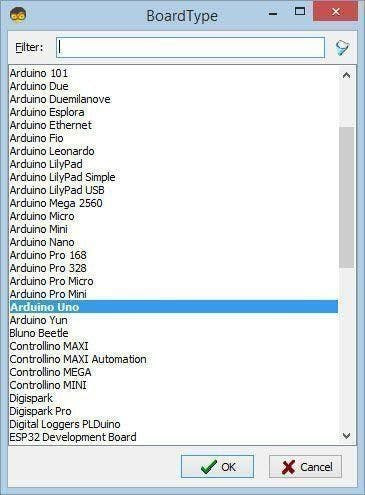
Start Visuino as shown in the first picture Click on the "Tools" button on the Arduino component (Picture 1) in Visuino When the dialog appears, select "Arduino UNO" as shown on Picture 2
Step 4: In Visuino Add Components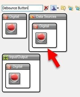
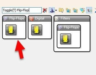
- Add "Debounce Button" component
- Add "Toggle(T) Flip-Flop" component
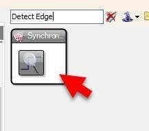
- Add 2X "Detect Edge(Digital to Clock)" component
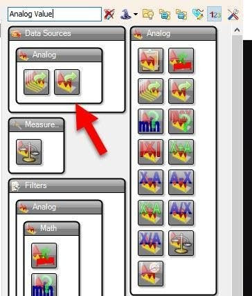
- Add "Analog Value" component
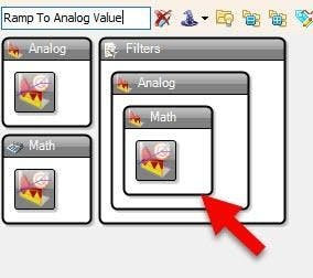
- Add "Ramp To Analog Value" component
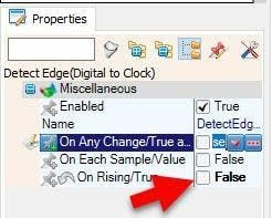
- Select "DetectEdge2" and in the properties window set "On Rising/True" to False
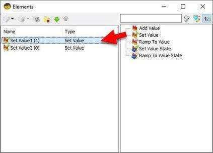
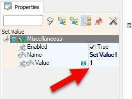
- Double click on the "AnalogValue1" and in the Elements window drag 2X "Set Value" to the left side and for "Set Value1" set in the properties window "Value" to 1
- Select "RampToValue1" and in the properties window set "Slope (Sec)" to 0.5
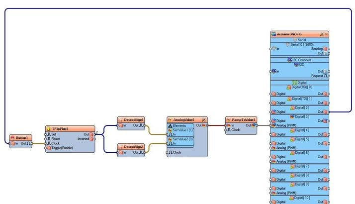
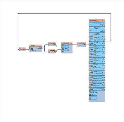
- Connect Arduino Digital pin [ 2 ] to "Button1" pin [Input]
- Connect "Button1" pin [Output] to "TFlipFlop1" pin [Clock]
- Connect "TFlipFlop1" pin [Output] to "DetectEdge1" pin [Input]
- Connect "TFlipFlop1" pin [Output] to "DetectEdge2" pin [Input]
- Connect "DetectEdge1" pin [Output] to "AnalogValue1" > "Set Value1 (1)" pin [Input]
- Connect "DetectEdge2" pin [Output] to "AnalogValue1" > "Set Value2 (0)" pin [Input]
- Connect "AnalogValue1" pin [Output] to "RampToValue1" pin [Input]
- Connect "RampToValue1" pin [Output] to Arduino Digital pin [ 3 ]
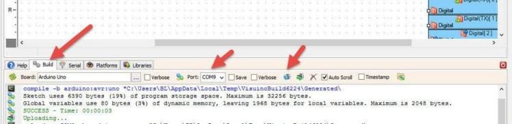
In Visuino, at the bottom click on the "Build" Tab, make sure the correct port is selected, then click on the "Compile/Build and Upload" button.
Step 8: PlayCongratulations! You have completed your project with Visuino. Also attached is the Visuino project, that I created for this tutorial, you can download it here and open it in Visuino:
Schematics, diagrams and documents
Code
Credits
Related products


Leave your feedback...