
 Of Music! Teaching Electronics With The Stm32 Nucleo1510840750_cover_image.jpg)
The Sound (and Sight) Of Music! Teaching Electronics With The Stm32 Nucleo

Made by mbparks / Environmental Sensing / Lights / Music
About the project
What if we could tap into this marriage of music and technology to make something even more amazing?
Project info
Difficulty: Difficult
Platforms: Arduino, MikroElektronika, STM32 Nucleo
Estimated time: 2 weeks
License: GNU General Public License, version 3 or later (GPL3+)
Items used in this project
Hardware components
![Operational Amplifier [Texas Instruments] LM324N Operational Amplifier](https://www.mouser.co.uk/images/texasinstruments/sm/TI_PDIP_14.jpg)


View all
Story
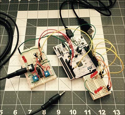
Figure 1: The Nucleo Light and Sound Machine controls the music and flashes LEDs in time to the music.
Over the last fifteen years or so, music has found itself encapsulated into digital bits. What if we could tap into this marriage of music and technology to make something even more amazing?
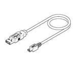
In this project we are going to add a visual representation of our music. We will take the audio from our favorite portable music player and electronically sample its waveforms to produce a stunning light show using LEDs. This project can be done both with and without a microcontroller. The LEDs can be driven directly using an operational amplifier or sent to an ST Nucleo via analog-to-digital conversion to add even more fun effects. When setting out to design this project, we aimed to strike a balance between cost, complexity, and educational value. But most importantly, we wanted a project that captured the imagination of students and empowered them to take the basic design and hack it to meet their own unique desires. The circuit is a basic audio amplifier circuit that, in principle, is used in tons of audio products. In a circuit that fits onto a tiny breadboard we can teach Ohm’s Law, voltage dividers, potentiometers, LEDs, capacitors, current limiting, operational amplifier theory, and line level audio! The beauty of the design is that it is self-contained and can be used without having to write any code or interface with a microcontroller, except to provide power to the op amp. Of course, you could provide power to the op amp using 3 AA batteries if so desired. You can use a USB cable (mini-B to standard-A) connected to the Nucleo from a PC to power the Nucleo, as well. The Nucleo is used to power the entire set up regardless of whether you complete it with option A or B instructions.
Materials
To make things super simple we are providing a pre-built shopping cart with all the correct components. Remove the RCA and USB cables from the cart if you already have them. No worries on selecting the wrong part by accident! We’ve also labeled each item in the BOM to corresponding part in the provided schematic.
The Bill of Materials (BOM) (See above) for this project is for the electronics as shown in Figure 1. In the demo video, a smartphone or MP3 player is connected to the 3.5mm Stereo jack (smartphone/MP3 player not included!)
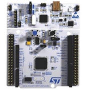
We will use an STM32 Nucleo F401RE microcontroller platform. The STM32 Nucleo is programmed using the C/C++ language, but we provide the code for you. Nevertheless, programming tools are free online at mbed.org.
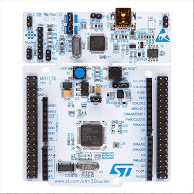
Figure 2: The STM32 Nucleo has a detachable, reusable programming card at the top that is removed once a project is done.
Tools:
Since this project is aimed towards classrooms and not electronics laboratories, we wanted to make sure that no hand tools or electronic test equipment was required. Of course, if you are teaching a course specifically geared towards electronics and have access to a multimeter or an oscilloscope, hooking it up the outputs of the audio jack makes for a very cool visualization of sound (Figure 2.) But to be sure, this is completely optional!
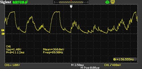
Figure 3: An oscilloscope is not needed for this project, but if you have one, you can visualize the sound with the oscilloscope.
If you plan to do more with the Nucleo than what is in this project, try looking at the Nucleo site on mbed.org: https://developer.mbed.org/platforms/ST-Nucleo-F401RE/
Here, you will find other projects and any additional information, such as this pin-out diagram of the Nucleo:

Figure 4: The STM32 Nucleo pin-out and other Nucleo information and projects can be found at mbed.org
Overview
Striving for simplicity, the circuit is very straightforward. We are taking audio from a computer or mobile device via its 3.5mm audio jack and splitting left and right audio channel so we can tweak each channel individually based on our preferences. Line level audio is very low voltage and not suitable to drive our LEDs or the Nucleo directly. That is why we are taking the audio and running it through an operational amplifier, often shortened to just “op amp”. Actually, if you look carefully at the schematic (located in the Resources Section) you will notice that each channel signal is run through two op amps. The first op amp provides amplification and the second op amp provides buffering.
Op amps are one of the workhorse components of circuit design. They can be used in wonderfully simple but also incredibly complex ways. Learning op amps is a key skill. For this project we are using the op amp in a configuration known as a “non-inverting “amplifier”. The alternative is an “inverting amplifier”. To understand the difference let’s take a quick look at the parts of analog signal.

Figure 5: Parts of an analog signal.
In a non-inverting amplifier the output will remain in phase with the input signal, in an inverting amplifier the output is 180-degrees out of phase. If you look at the schematic you will notice that the output of the first op amps feeds back into the inverting terminal via a small network of resistors. The arrangement of resistors is known as a voltage divider circuit. It allows us to control the amount of amplification or gain the op amp will perform on the input signal. Using a fixed resistor and variable resistor (the one we’re using is referred to as a trimming potentiometer or trimpot for short) will allow us to manually control the gain. By turning the trimpot we vary its resistance, and in turn the gain of the op amp which will cause the LEDs to glow more brightly or more dimly depending on how it’s adjusted.
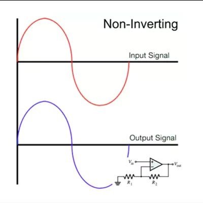
Figure 6: Non-inverting op amp signal.
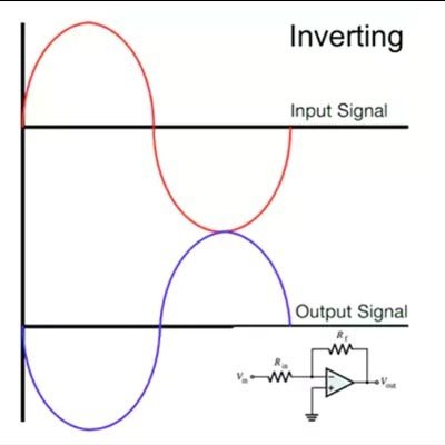
Figure 7: Inverting op amp signal.
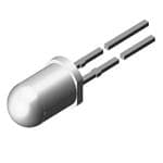
At the output of the second op amp we are using a resistor and capacitor in parallel to create a high pass noise filter to get rid of any RF noise the circuit might pick up. Lastly the LED and resistor in series are there to provide the light show. The LED is obviously doing the blinking and the resistor provide current protection for the diode.
Lastly, some notes about 3.5mm Tip-Ring-Sleeve audio jacks. The signal ground is commonly found on the outermost conductor, which is called a sleeve. The left channel is typically on the tip, and the right channel is sent out over the ring (Think “R” for right and ring).
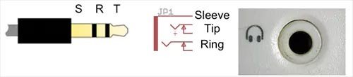
Figure 8: A 3.5mm Tip-Ring-Sleeve audio jack diagram (left), schematic of the jack (middle), and PC speaker input (right) to play the music using built-in PC speakers if you don’t have portable speakers. Audio jack part number: 172-2208 or 172-8362-E.
The Build (Building the Electronics)
Conveniently all the components will fit on a single, small breadboard. The build is very straightforward. The first nine steps are used regardless if you are going to use the Nucleo or not. The final steps will vary depending if you desire to use the Nucleo or not. Option A will simply drive two LEDs without the Nucleo (using AA batteries instead of the Nucleo to power it.) Option B will require a computer to program the Nucleo and then perform the light show as we have programmed in our code. If you stop after implementing Option A, then you can still use the Nucleo for power.
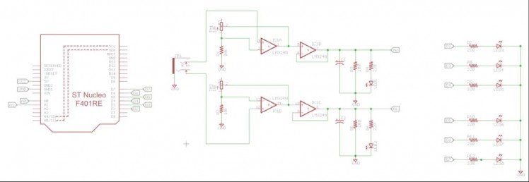
Figure 9: Schematic of the STM32 Nucleo Sight and Sound open source hardware project. (NucleoLightSoundEducationSchematic.png)
Instructions: Print out the schematic as listed in the Resources section.
- Carefully place the op-amp favoring one end of the breadboard, but leave about 3 rows available on the end you choose. Be aware that each pin has a different purpose. The datasheet will show you what each pin does and how they interconnect internally. Notice that DIP ICs have a dot (either printed or a depression on the package) near pin 1. There also tends to be a small “U”-shaped depression towards the top of the chip, with pin 1 being to the left. I cannot stress enough the importance of buying an extra IC or two when ordering your parts. From bent pins that break off, to reversing Vcc and GND, once chips are broken there is no repair. Have a few extra on hand will give you peace of mind when experimenting with a design.
- Next place the trimpot so that the central wiper pin is connected to op amp pin 5, and that an outer pin of the trimpot connects to op amp pin 2. Recall, we are splitting out the left and right audio channel so we are going to repeat this for the other side of the op amp. This time, the central wiper pin is connected to op amp pin 10 and that an outer pin of the trimpot connects to op amp pin 13.
- Add the fixed resistor to each trimpot, with one end of the resistor attaching to the trimpots and the other to GND. Connect to the same outer pin of the trimpots that you used in step 2.
- Place the 3.5 mm audio jack onto the breadboard. Be sure to align the audio jack so each pin gets its own row on the breadboard.
- Connect pin 5 of the audio jack (tip, left channel) to pin 12 of the op amp.
- Connect pin 2 of the audio jack (ring, right channel) to pin 3 of the op amp.
- Connect pin 1 of the audio jack (sleeve, ground channel) to pin 11 of the op amp.
- Connect pin 6 of the op amp to pin 7 of the op amp chip. (This is the feedback loop)
- Connect pin 8 of the op amp to pin 9 of the op amp chip. (This is the feedback loop)
- Connect pin 1 of the op amp to pin 5 of the op amp.
- Connect pin 10 of the op amp to pin 14 of the op amp.
Continue on with at least Option A, which does not require code (but requires the Nucleo for its power source.) You can add Option B which controls many more LEDs and uses the MCU of the Nucleo and includes programming as included in the Software section.
Option A: LEDs driven by the output of the op amp
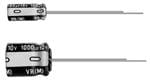
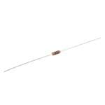
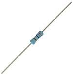
- Place a 100-ohm resistor, 220-ohm resistor, and a 0.1uF capacitor onto the board so that they all share a common node (the positive lead of the capacitor). Replace this 220-ohm resistor with the extra 100-ohm resistor if the LED isn’t bright enough.
- Connect the anode of the LEDs to the other end of the 220-ohm resistor.
- Connect the cathode of the LED, the negative lead of the capacitor and the free end of the 100-ohm resistor to a common node. Wire this node to ground.
- Repeat steps 1 through 3.
- Wire the output of op amp pin 7 to the common node shared by the two resistors and positive lead of the capacitor. This will show the intensity of the right channel.
- Wire the output of op amp pin 8 to the common node shared by the other two resistors and positive lead of the second capacitor. This will show the intensity of the left channel.
- Skip the software section if you do not continue to Option B.
Option B: LEDs driven by the Nucleo
- Place six 220-ohm resistors on the breadboard.
- Place six LEDs on the board, each one with the anode connected to one end of a 220-ohm resistor. The cathode of all LEDs can share a common ground.
- Take the free ends of the first three resistors and attach one to Nucleo pin D2, one to pin D3, and the last one to pin D4.
- Take the free ends of the remaining resistors and connect one to Nucleo pin D5, one to pin D6, and the last one to pin D7.
- Connect op amp pin 7 (output from the left channel) to Nucleo pin A0.
- Connect op amp pin 8 (output from the right channel) to Nucleo pin A1.
Software
When you are ready to integrate the Nucleo into the project, we will need to first program the Nucleo to do what we desire. In this example, we will sample the output of each channel's audio using the onboard analog-to-digital converter. Depending on the intensity of each channel's audio, and in turn the voltage level of the op amp’s output, we will drive 1, 2, or 3 LEDs per channel. So if the audio is very low we will drive 1 LED, and if it is very loud we will drive 3 LEDs.
The program we are running on the Nucleo is pretty straightforward:
- Sample the analog value of both the left and right channel and digitize.
- Assign the digitized values to a variable so we can use it throughout the current loop iteration.
- Look at the digitized value of the channel and determine if its volume is low, medium, or high.
- You can tweak the values of the variables that trigger the low, medium, and high LEDs. You can read more in the software section, look for the discussion on lowCutoff, mediumCutoff, and highCutoff. For now, the default logic is as follows:
a. If the channel is sampled to be below 10, then it is nearly perfectly quiet, turn off all the LEDs
b. If the channel is sampled to be between 10 and 1000, then turn on just one LED since the volume is low.
c. If the channel is sampled to be between 1000 and 2000, then turn on two LEDs since the volume is medium.
d. If the channel is sampled to be greater than 2000, then turn on all three LEDs since the volume is high.
The program code for the Nucleo is listed below and can also be found in the Resources section as main.cpp or as a text file named LightSound_NucleoCode.txt:
- #include "mbed.h"
- AnalogIn leftChannel(A0); // left channel
- AnalogIn rightChannel(A1); // right channel
- DigitalOut leftLED_LOW(D2);
- DigitalOut leftLED_MED(D3);
- DigitalOut leftLED_HIGH(D4);
- DigitalOut rightLED_LOW(D5);
- DigitalOut rightLED_MED(D6);
- DigitalOut rightLED_HIGH(D7);
- void setLeftLED_OFF();
- void setLeftLED_LOW();
- void setLeftLED_MED();
- void setLeftLED_HIGH();
- void setRightLED_OFF();
- void setRightLED_LOW();
- void setRightLED_MED();
- void setRightLED_HIGH();
- int main() {
- float leftChannelSignal;
- float rightChannelSignal;
- float lowCutoff = 10;
- float mediumCutoff = 1000;
- float highCutoff = 2000;
- printf("nTurn Sound Into Lightn");
- while(1) {
- leftChannelSignal = leftChannel.read(); // Converts and read the analog input value (value from 0.0 to 1.0)
- rightChannelSignal = rightChannel.read(); // Converts and read the analog input value (value from 0.0 to 1.0)
- leftChannelSignal = leftChannelSignal * 3300; // Change the value to be in the 0 to 3300 range
- rightChannelSignal = rightChannelSignal * 3300; // Change the value to be in the 0 to 3300 range
- printf("L Channel = %.0f mVn", leftChannelSignal);
- printf("R Channel = %.0f mVn", rightChannelSignal);
- //LEFT CHANNEL
- if (leftChannelSignal <= lowCutoff) {
- setLeftLED_OFF();
- }
- else if (leftChannelSignal > lowCutoff && leftChannelSignal <= mediumCutoff) {
- setLeftLED_LOW();
- }
- else if (leftChannelSignal > mediumCutoff && leftChannelSignal <= highCutoff) {
- setLeftLED_MED();
- }
- else {
- setLeftLED_HIGH();
- }
- //RIGHT CHANNEL
- if (rightChannelSignal <= lowCutoff) {
- setRightLED_OFF();
- }
- else if (rightChannelSignal > lowCutoff && rightChannelSignal <= mediumCutoff) {
- setRightLED_LOW();
- }
- else if (rightChannelSignal > mediumCutoff && rightChannelSignal <= highCutoff) {
- setRightLED_MED();
- }
- else {
- setRightLED_HIGH();
- }
- //wait(0.2); // 200 ms
- }
- }
- //LEFT CHANNEL
- void setLeftLED_OFF(){
- leftLED_LOW = 0;
- leftLED_MED = 0;
- leftLED_HIGH = 0;
- }
- void setLeftLED_LOW(){
- leftLED_LOW = 1;
- leftLED_MED = 0;
- leftLED_HIGH = 0;
- }
- void setLeftLED_MED(){
- leftLED_LOW = 1;
- leftLED_MED = 1;
- leftLED_HIGH = 0;
- }
- void setLeftLED_HIGH(){
- leftLED_LOW = 1;
- leftLED_MED = 1;
- leftLED_HIGH = 1;
- }
- //RIGHT CHANNEL
- void setRightLED_OFF(){
- rightLED_LOW = 0;
- rightLED_MED = 0;
- rightLED_HIGH = 0;
- }
- void setRightLED_LOW(){
- rightLED_LOW = 1;
- rightLED_MED = 0;
- rightLED_HIGH = 0;
- }
- void setRightLED_MED(){
- rightLED_LOW = 1;
- rightLED_MED = 1;
- rightLED_HIGH = 0;
- }
- void setRightLED_HIGH(){
- rightLED_LOW = 1;
- rightLED_MED = 1;
- rightLED_HIGH = 1;
- }
Good coding practice would dictate that since the left and right channels are performing similar tasks that we could incorporate both into a single functions. However, we kept them separate to help with understanding what’s going on with each channel and so you can create different effects for each channel independently.
Now that we understand what the code is doing, let’s have quick discussion of what is needed to actually get the code onto the Nucleo. To make things as simple as possible to start, you can simply copy the code we’ve provided above and paste into the tool.
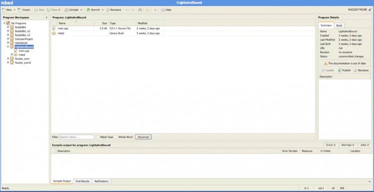
Figure 9: The free mbed.org programming tool for the Nucleo. Shown is the Works Space Manager window. (mbed_workspaceManager.png)
First you will need to download the USB driver for the Nucelo-F401RE. Click on Software and then Development Tool Software to find the “part number” for the download package: STSW-LINK009. Or, you can find it by starting from here: https://developer.mbed.org/platforms/ST-Nucleo-F401RE. This site is also good for more information on the Nucleo, including firmware upgrades. You should check for the latest firmware upgrade every time you get a new board as good practice. Full instructions are offered on how to make these downloads if you are using the Nucleo for the first time, or with a new PC.
You can head over to mbed.org and create a free account. The nice thing about the Nucleo is that you can use the programming environment in the browser so it’s always up to date. Once you are logged in you should see the “Compiler” link in the top right of the website, click on that. This will open up your workspace where all your projects will reside. From here follow these steps:
1. In the top left click on “New” and select “New Program”.
2. In the dialog box make sure the following are set:
- Platform: “NUCLEO-F401RE”
- Template: “Empty program”
- Program Name: Whatever you wish. I chose “LightsAndSounds”
3. This will create your default files needed, including “main.cpp”. Double click that file to open the editor.
4. Paste in the code we’ve provided.
5. Click “Save All”
6. Click “Compile”. This will create the necessary .bin file that you will drop onto your STM32 Nucleo. You will be asked where you want to save the file to on your computer. Usually I choose the Desktop.
7. Installing code on the STM32 Nucleo is as simple as dragging the file from wherever you saved it onto the STM32 Nucleo, just as you would click-and-drag any file onto a USB thumb drive.
That’s it. After the .bin file is transferred the Nucleo will automatically reboot and start running your application.
Assembly
There is no additional assembly required! Just hook up your audio source to the audio jack of your circuit. Of course, you could take this project and if you had the resources to teach 3D printing you could have students print an enclosure to house breadboard. But again, it is not required and the circuit will work happily with no enclosure.
I am using a 3.5mm splitter on the output of my phone so that I can send the sound to both the circuit we’ve built and a small speaker so I can hear the music as well as see it. I am using 3.5mm male-to-male extender cable from the splitter into the audio jack. Even if we didn’t use the Nucleo as part of the circuit before, we are going to use it now to provide power to the op amps if nothing else. Insert the USB cable into your computer and the other end into the Nucleo. You should notice the little LEDs on the board begin to glow. Simply attach the Vcc and GND rails of the breadboard to the Vcc and GND pins on the Nucleo. When you are comfortable to move on to interfacing your circuit with the Nucleo, don’t forget to wire the outputs of the op amps into the analog inputs of the Nucleo as discussed previously.
Project in Action
Finally, it’s time to fire up your music app of choice, select your favorite tunes and watch the LEDs begin to rhythmically glow in beat with your music. Depending on how your music file (e.g. MP3, WAV) was created audio may not appear on both channels. That’s okay, you just might not see both LEDs flashing to beat of the music. If the 3.5mm jack is not plugged in you might notice the LEDs glowing, that’s fine! It’s an aspect of line level audio and our circuit.
Schematics, diagrams and documents
Code
Credits
mbparks
Mike Parks is the owner of Green Shoe Garage, a custom electronics design studio and security research lab located in Southern Maryland. He produces content for the Gears of Resistance which shares news and tips for those interested in the maker movement, open-source hardware and software, STEAM education, citizen science, and digital citizenship. He is also an extra class ham radio operator, a licensed Professional Engineer in the state of Maryland, and most notably a dad.
Related products


Leave your feedback...