
Sop System - Metal Gear Solid Inspired Nerf Project

Made by 314Reactor / Displays / Games & Gaming / Sensors / Wearables
About the project
An ID locking Nerf/Raspberry Pi project inspired by the SOP ID System from the game Metal Gear Solid.
Project info
Difficulty: Moderate
Platforms: Adafruit, Raspberry Pi, Python, Pimoroni
Estimated time: 1 day
License: GNU General Public License, version 3 or later (GPL3+)
Items used in this project
Hardware components


View all
Story
Key Goals:
- Make a Nerf Blaster than can only be fired by users with an authorised fingerprint
- Be able to get sensor data on the user and environment
- Be able to remotely administer the system
I’ve had the idea now for some time to make a Metal Gear Solid 4 inspired project based on the SOP System that’s in the game – so when Digitspace asked me if I had any project ideas I told them about it and they were happy to sponsor the project and give me the parts! So thanks to them for enabling me to make this project!
So, in a nutshell the SOP System in game is a system than controls all military hardware and ensures that unauthorised users can’t utilise tools if they aren’t registered on the system.
For further explanation check out the in game cut-scene with extra details:
So with the project plan and parts from Digitspace I constructed the hardware around a Nerf Blaster and got to work!
Stuff
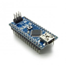
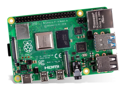
- Raspberry Pi Zero W
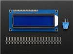
- LCD Screen
- GPS Module
- Pulse Sensor
- Touch Button
- Environmental Sensor
- Proximity Sensor
- Powerboost 500c
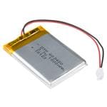
- 1200mah lipoly Battery
- Fingerprint Sensor
- Protoboard
- Standoffs
- Jumper jerky F-F
- Jumper jerky M-F
- USB to UART cable
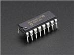
- MCP3008
- Wire spool
- Resistor set
- Stripboard
- Tie Wraps
- Various headers
- Nerf Blaster
- Heatsink
- Micro USB cable
- USB shim
- Servo
- SD Card
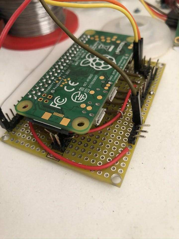
First up I started soldering up the header for the Raspberry Pi for all the inputs and outputs required, this enables a swap out of the Pi if needed:
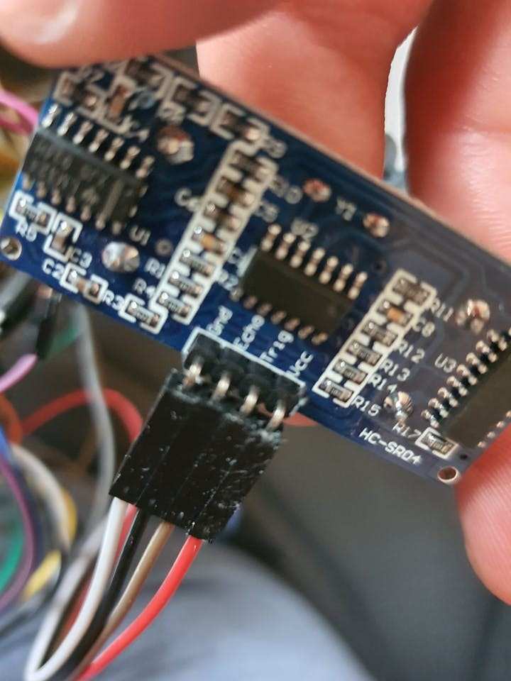
You can also see there another PCB, that is for the MCP3008 chip and the ultrasonic sensor components, following the instructions here and here.
I wired up the GND, 3v and 5v pins to rails on the PCB in order to have an easy way to power the other components.
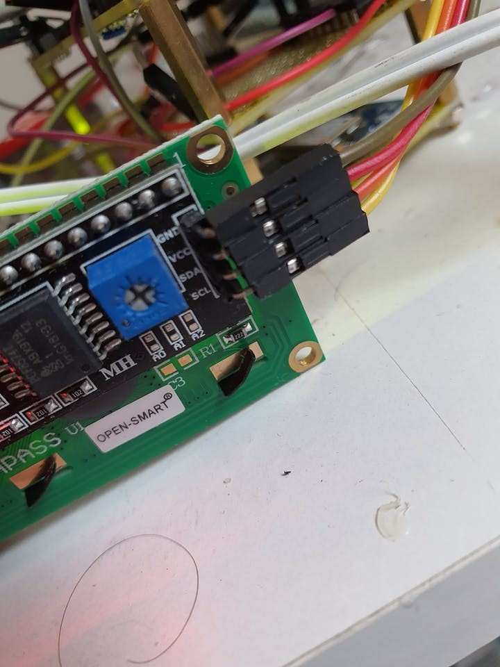
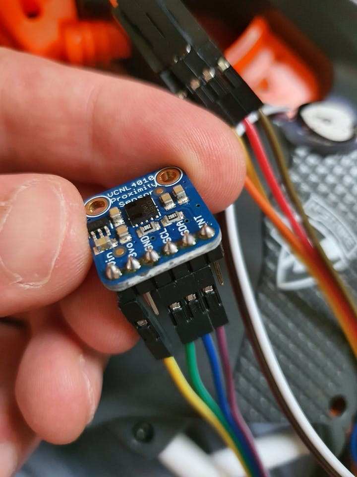
I’ve also wired up the I2C outputs for the LCD screen, the environment sensor and the proximity sensor as per the instructions here, here and here.
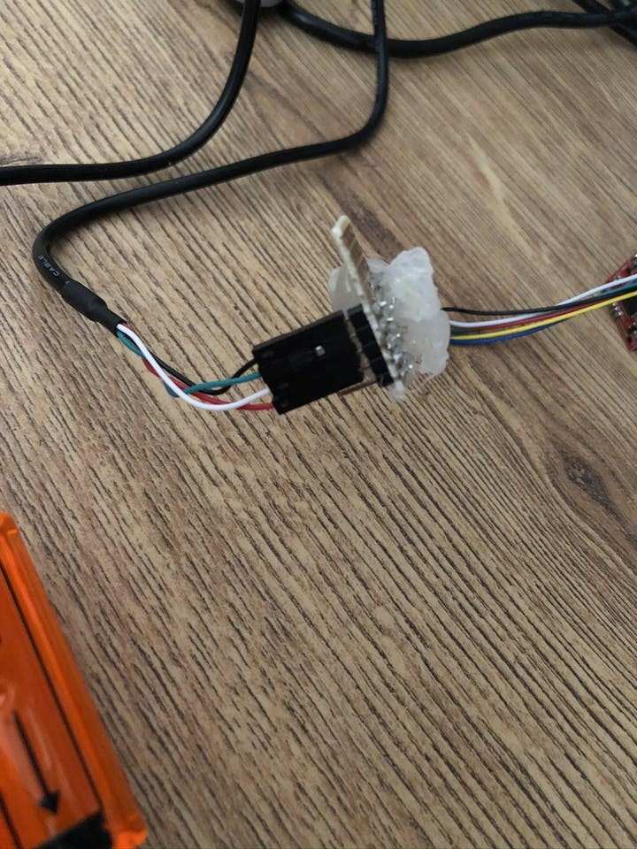
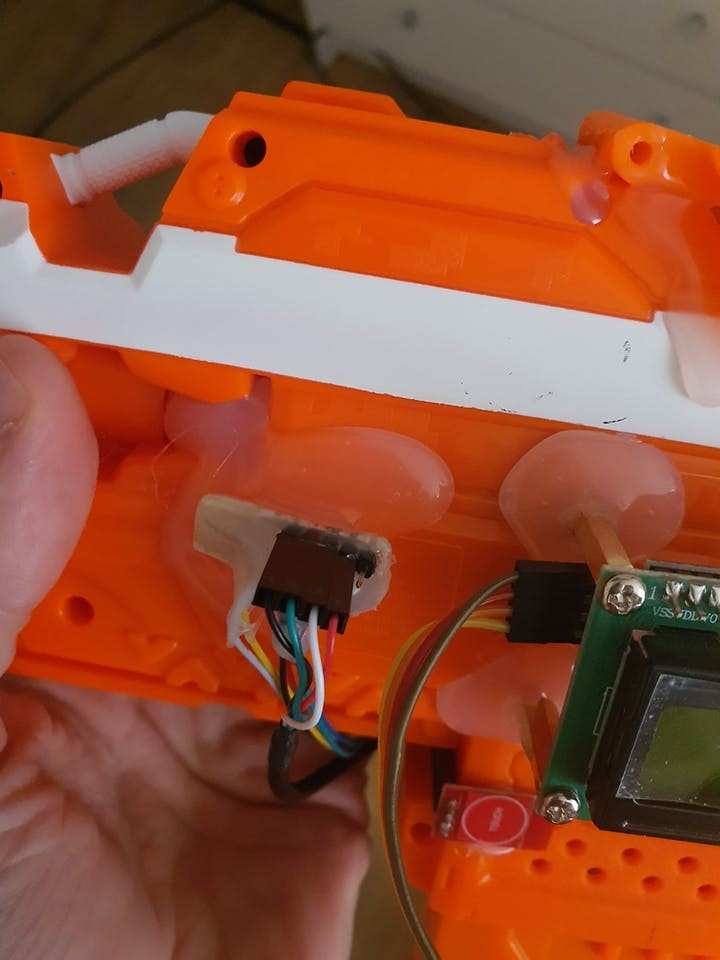
The fingerprint reader will be connected via USB to TTL converter, so this will be plugged into the USB slot with the USB shim. I used a cut off portion of a strip-board to make a connector for bridge in-between the PCB and the USB cable.
I got another PCB and soldered in the GPS module:
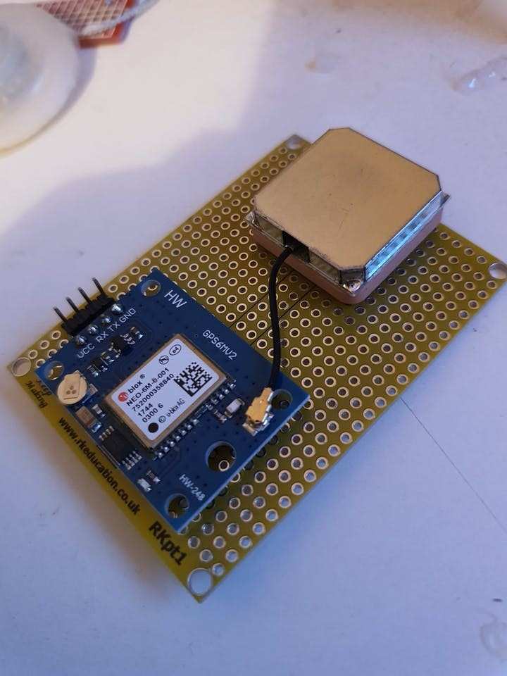
This will be wired up to the Pi via the serial pins as per these instructions.
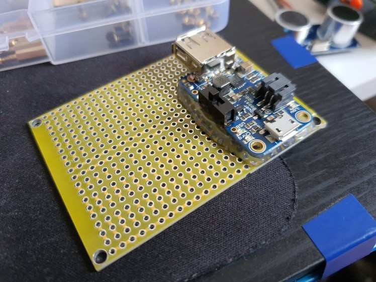
A fourth PCB is for the Powerboost 500c:
Next up I soldered a header on the Pi Zero W and put the heat-sink on:
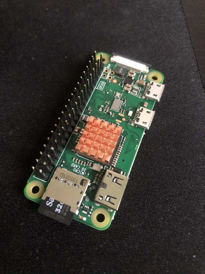
Some of the pins closer to the Pi had to be bet a bit to fit under the Pi when it’s placed on the header:
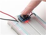
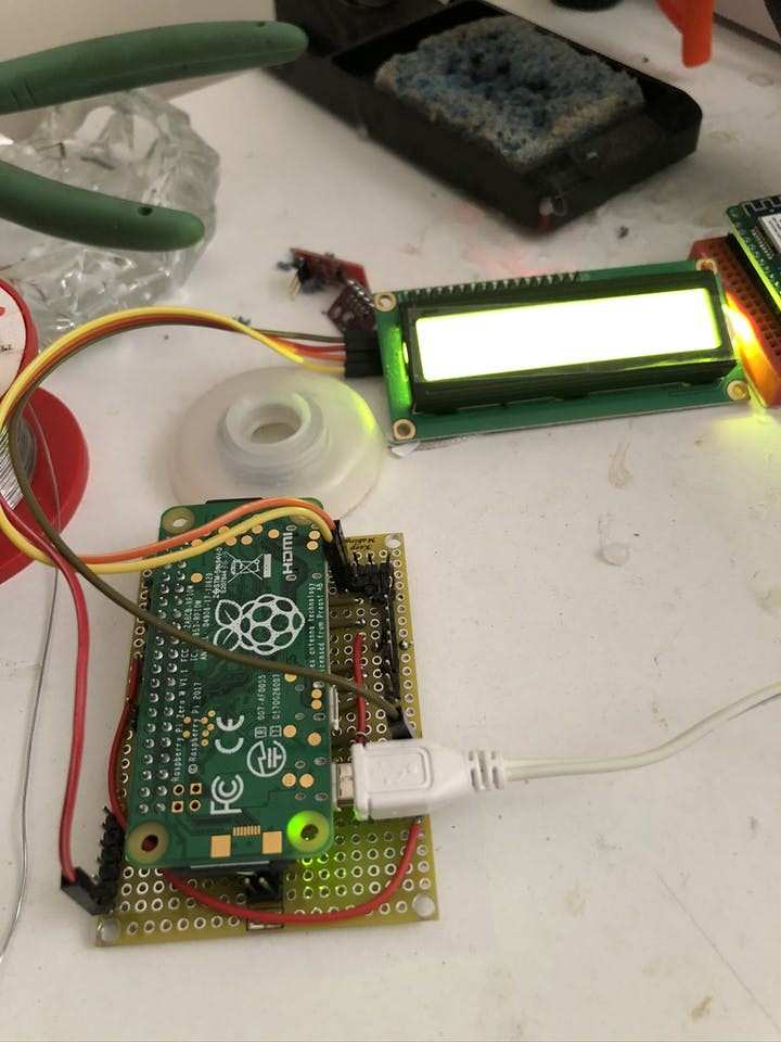
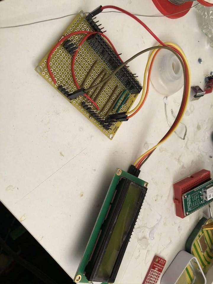
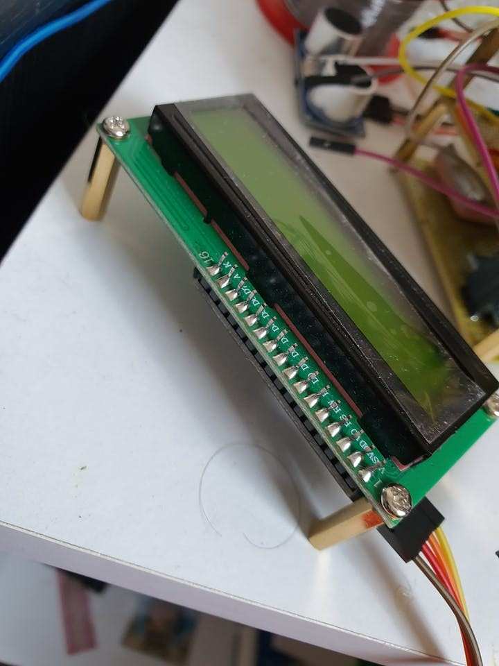
One of the first things I hooked up to test was the LCD screen:
1 / 3
I then began to hook up the other components, such as the proximity sensor, fingerprint reader, the ultrasonic sensor and the button:
1 / 3

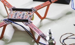
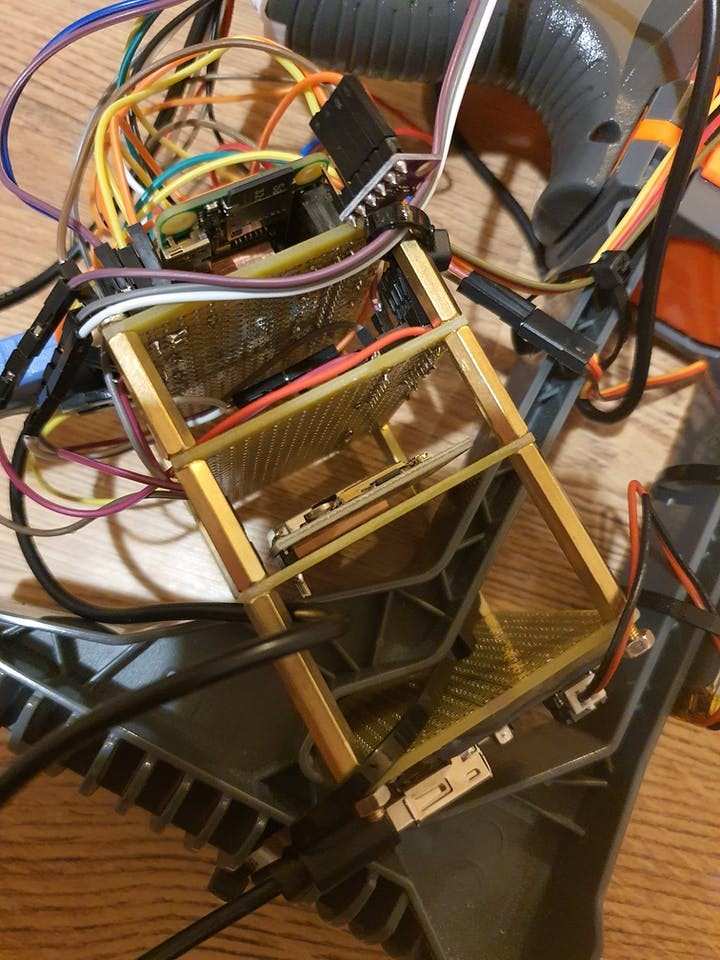
As you can see from the above picture the PCB layers have been connected with standoffs and screws so that the layers are nicely kept together.
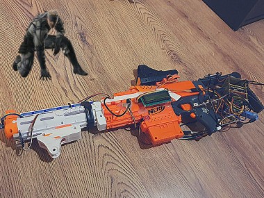
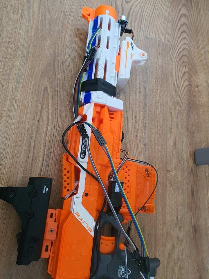
Next I placed the servo on the Nerf Blaster (the Nerf Stryfe, which I chose because it has the ability to be locked from firing by a button within the top part) the servo is placed in a way that it can actuate the button in order to lock/unlock the blaster:
1 / 2
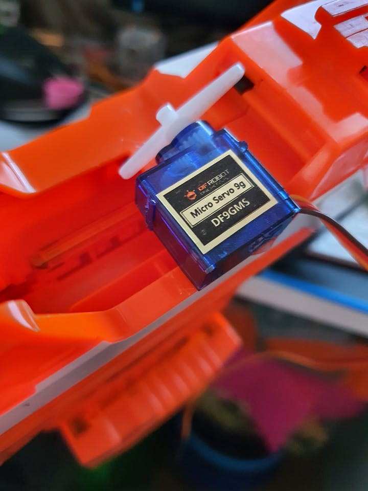
You can also see that I have put the cover on over the top in order to prevent manual activation of the button without the servo.
I set up some standoffs on the LCD screen so that it can be attached to the Blaster easier and keep the wires clear:
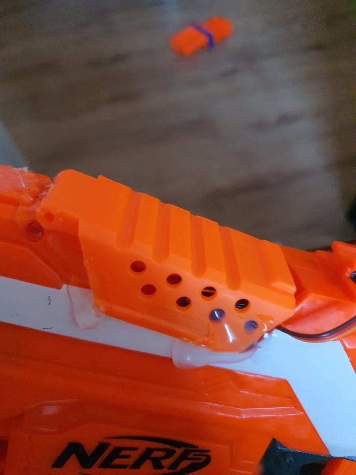
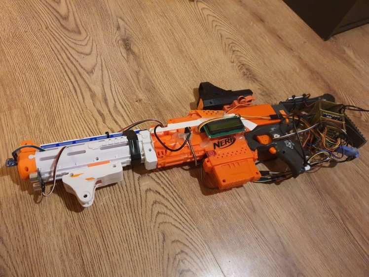
I attached the ultrasonic sensor below the muzzle of a Nerf barrel and also put the proximity sensor on the front to detect shots:
1 / 2
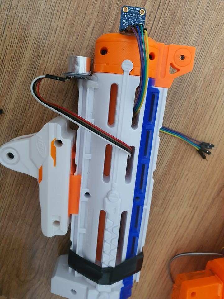
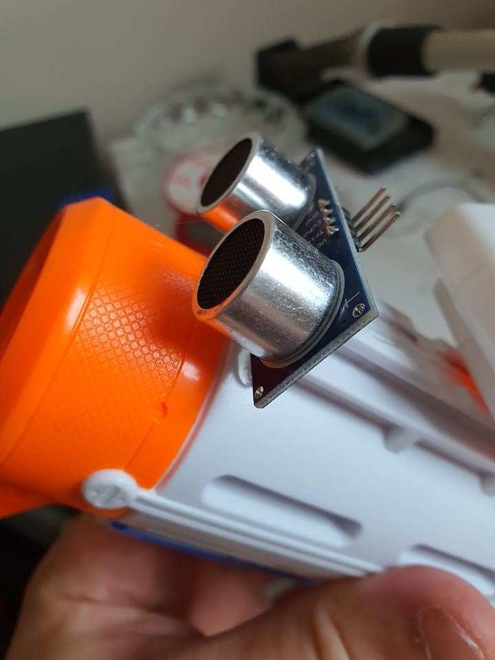
These will all be hooked up with jumper wires.
Then I glued the fingerprint sensor onto the side with hot glue where it will be accessible with the users index finger:
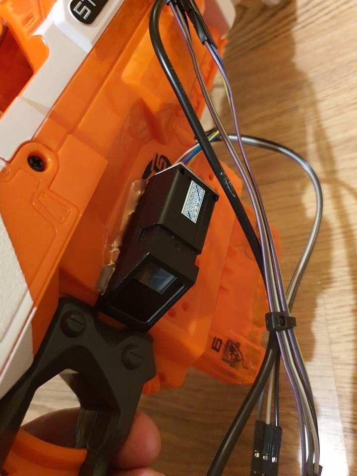
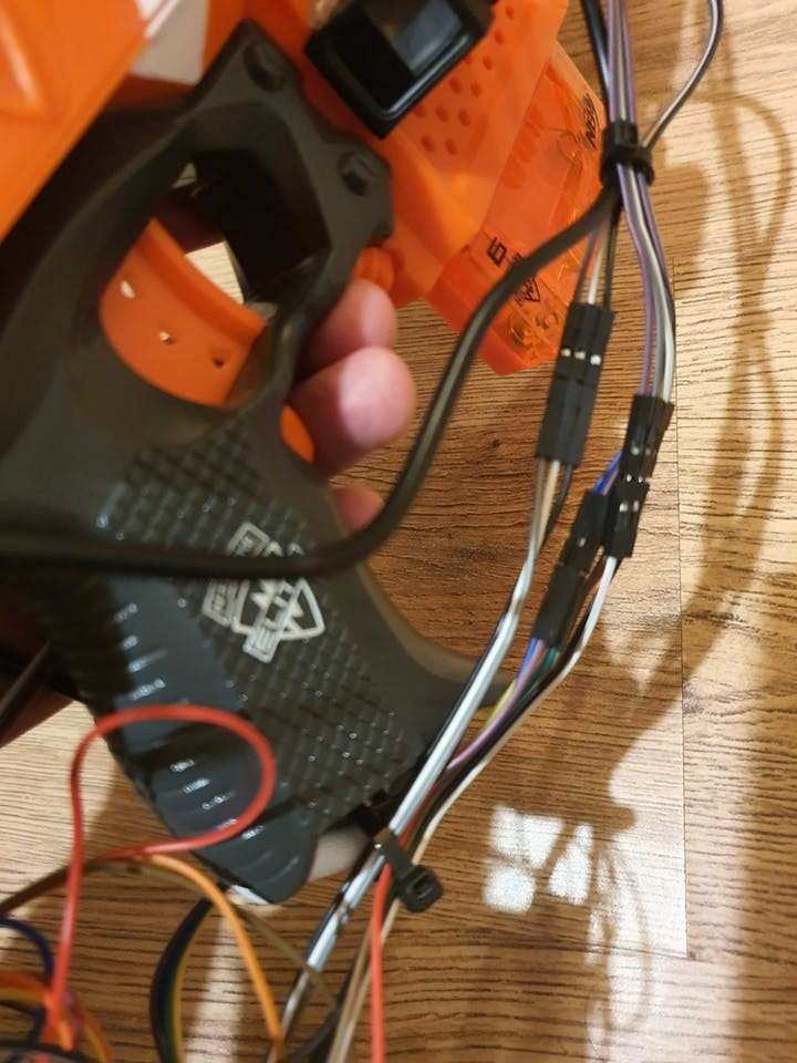
Then I glued the bridge between the USB cable and the fingerprint reader onto the side of the Blaster, with the touch button for reloads just below it:
1 / 2

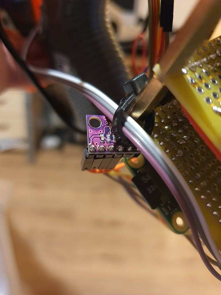
I then screwed the environment sensor onto the top of the PCB:
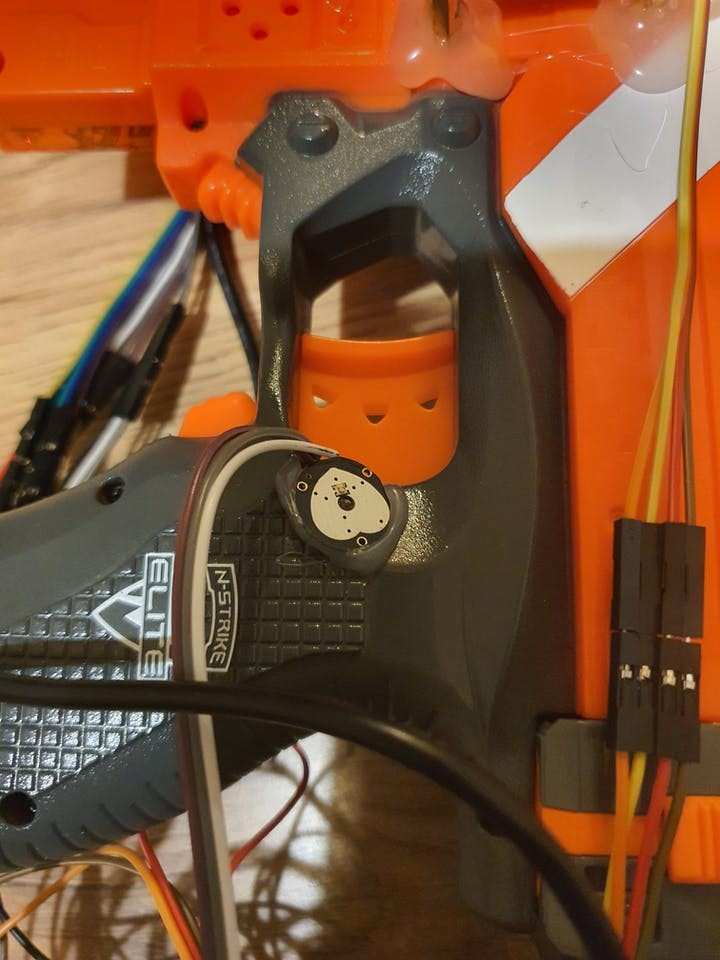
Next the pulse sensor was attached with hot glue where it can read the pulse from the users thumb:
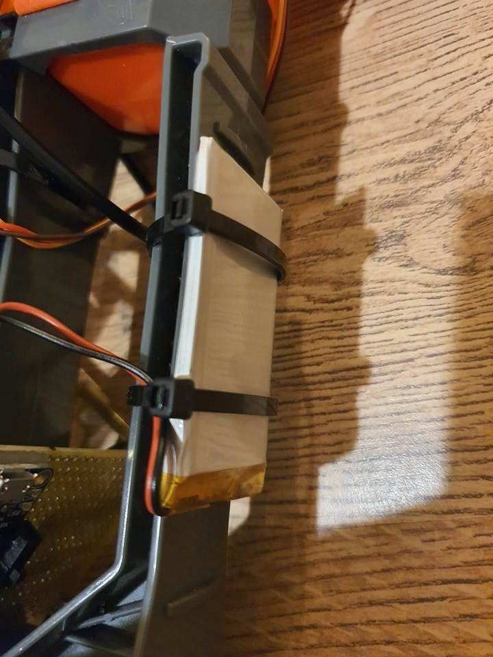
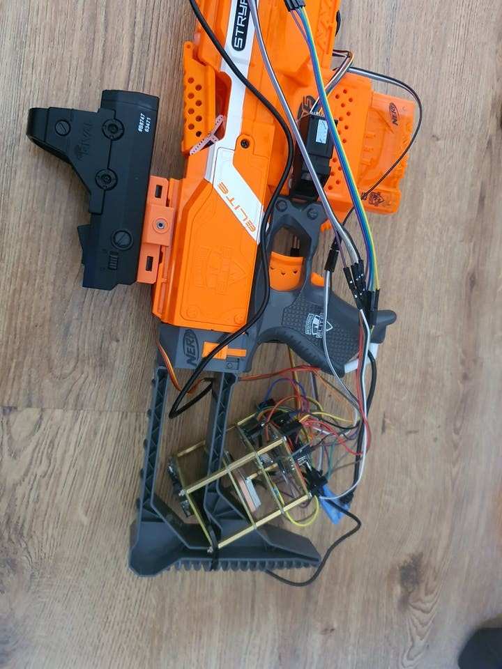
I attached the whole unit to the stock of the blaster and the battery to the top with tie-wraps:
1 / 2
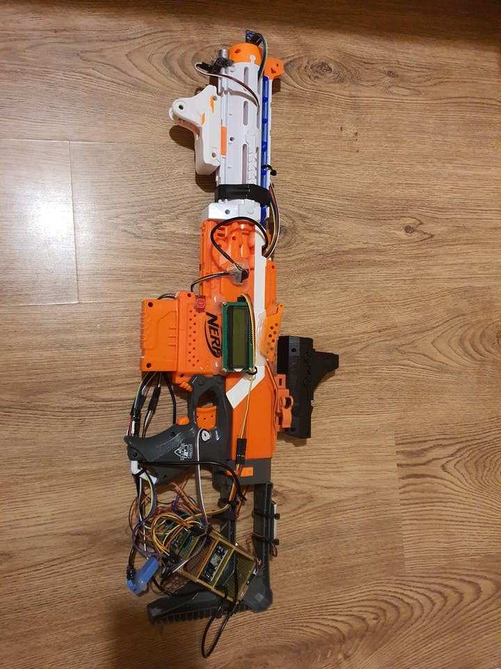
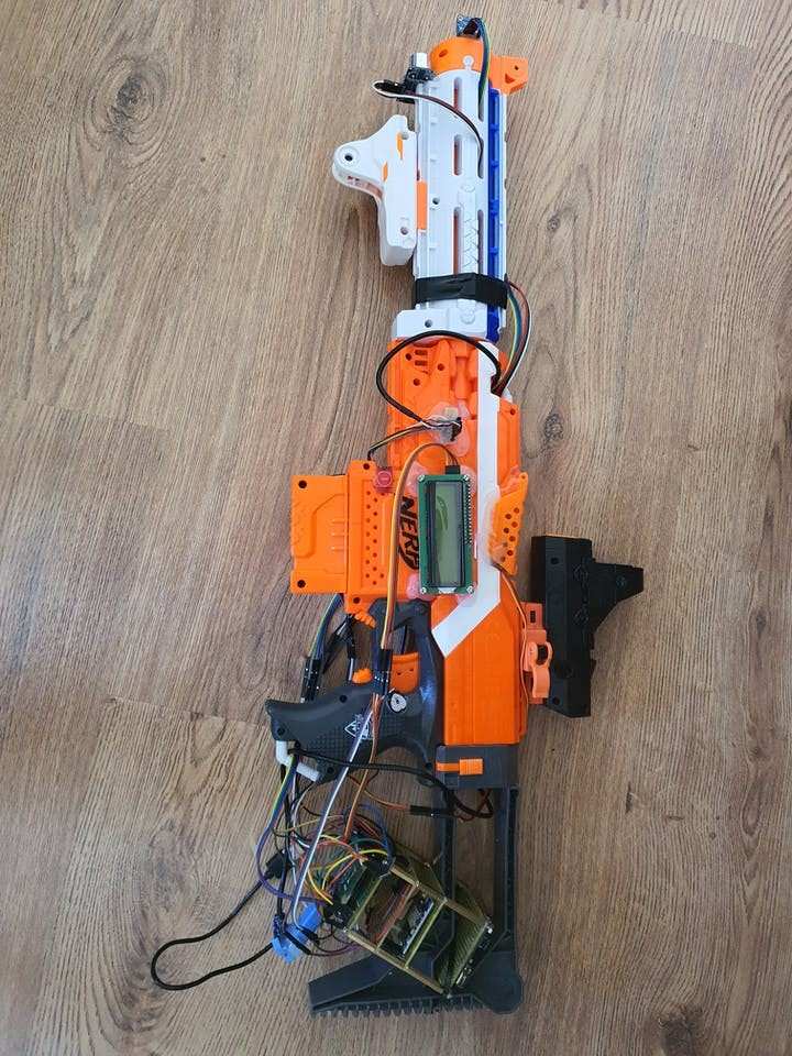
Once everything was hooked up and tidied a bit with more tie-wraps it looked like this and was ready to go:
1 / 5
I setup the Pi with PiBakery. I enabled SSH, I2C and H/W Serial.
You can grab the code from my GitHub lets go over the modules and what they do:
sop_admin:
Requires https://pypi.org/project/qprompt/ to construct the menus, this is where all the other modules are called from and data is returned to the user in order to remotely control the Nerf Blaster.
It also starts a thread on the heart-rate monitor, so if the BPM is 0 it determines that the blaster has been dropped and thus locks it, to prevent someone else from using it if they aren’t the authorised user.
This is also here the user counter is held so that multiple users can be registered with the Blaster, however the get templates function in the fingerprint sensor code doesn’t return the number of prints so this currently does not work.
sop_user_login:
This handles all the logins and locks of the blaster as well as the unconditional unlock that bypasses the BPM check.
ammo_counter:
This is what handles monitoring the remaining ammo, including reloads etc. as well as displaying to the screen rounds left. Requires the Adafruit library for the proximity sensor: https://github.com/adafruit/Adafruit_Python_VCNL40xx/tree/master/Adafruit_VCNL40xx
display_out:
Requires the RPi_I2C_driver from below; this is what has all the functions for drawing to the LCD screen, the two functions allow the 2 rows of the screen to have their text changed independently. It also has functions for turning the back-light on and off but these don’t seem to work from the RPi_driver library.
environment_sensor:
This is from https://www.controleverything.com/content/Barometer?sku=BMP280_I2CSs#tabs-0-product_tabset-2 – it has one function that returns data from the I2C bus to the admin module.
fingerprint_worker:
This is from https://github.com/adafruit/Adafruit_CircuitPython_Fingerprint – it handles the registration of new fingerprints as well as authorisations, deletions and showing numbers of fingerprints on file. Showing the number of prints doesn’t work though, it seems always return 0.
gps_runner3:
This is from https://ozzmaker.com/using-python-with-a-gps-receiver-on-a-raspberry-pi/ – it should return the Lat/Long coordinates of the GPS module.
heart_check:
This contains the class for initialising the pulsesensor and returning BPM.
locker:
This controls the PWM output for the servo in order to lock/unlock the blaster. It also sends the information on whether the system is locked or unlocked to the LCD display.
MCP3008:
This is from http://fromhttps://github.com/tutRPi/Raspberry-Pi-Heartbeat-Pulse-Sensor it handles all the interface required for the MCP3008 chip for the heartrate sensor.
pulsesensor:
This is from https://github.com/WorldFamousElectronics/PulseSensor_Amped_Arduino – it interfaces with the MCP3008 module in order to receive the BPM from the heart-rate sensor.
range_runner:
This controls the ultrasonic sensor output and receiving input to calculate the time difference and thus the distance to whatever the blaster is pointing at.
RPi_I2C_driver:
This is from http://www.recantha.co.uk/blog/?p=4849 and is the controller for the LCD screen.
There’s probably a few bugs and stuff that can be streamlined here; in a future version I’ll probably revisit the code and sort it out a bit more, but for now it’s functional.
In ActionAs you can see it works pretty well – it matches the goals of the project nicely. You can remotely register new fingerprints, delete them, lock/unlock the system check ammo, muzzle distance, environment data (temp/humidity) and get users to log in and register their prints.
There are some issues however; such as the servo moving about a bit when it’s supposed to be still, which can be heard throughout the video. I had this in my prior project though – Fingerprint ID Nerf – it’s odd and makes a bit of noise but it doesn’t move enough to affect the operation of the system.
I also couldn’t get the GPS to get a fix; which is a shame. I think if I was to go outside for a while I would get a satellite fix. This would have returned the Lat/Long coordinates of the system.
The final issue I found is that the function for returning the number of registered fingerprints always returns 0; this is using a library as noted above so there may be a bug in there I need to investigate.
Other than that, it can register new users and confirm their ID via the fingerprint reader, it will also successfully deny unauthorised fingerprints and keep the blaster locked.
The servo was relatively stable and kept the blaster in the state it was meant to be in, despite its odd small movements. The cover also prevents a manual activation of the system without proper ID.
FinallyOverall I’m happy with this, it could definitely do with some better looks and streamlining of the wiring etc in order to make it less messy and less likely to break/get caught on something. But for now it works well and does what I want.
I will return to this project at some point and improve upon it now I have a good base to work from.
I hope you enjoyed this project; let me know what you think, are there any improvements I could make? Do you have any further suggestions for extra functionality?
I’d like to improve the wiring on the next version and if I want to add any more sensors I’d probably need a decent breakout. In order to allow for more pins and make the wiring far tidier.
There’s also the bugs above I’d need to iron out in order to make it better, including the GPS, although I’m sure this was just down to not being able to get a satellite fix as it was returning data from the Serial port.
Thanks for checking out the project! I’ll see you next time.
“I want one.“

“I want one.“
Code
Credits
Related products


Leave your feedback...