

Smart Switch Using Arduino And Alexa

Made by Ruchir / Home Automation / Sensors / IoT
About the project
Temperature sensor is used to control a switch (relay) to turn on or off the device.
Project info
Difficulty: Moderate
Platforms: Amazon Alexa, SparkFun, Texas Instruments
Estimated time: 2 hours
License: GNU General Public License, version 3 or later (GPL3+)
Items used in this project
Hardware components


Story
List of materials
- 12V Relay Module == > $ 4.20
- Arduino uno == > $ 8
- DHT11 temperature sensor == > $ 3
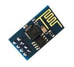
- ESP8266 Module == > $ 4.70
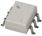
- 4N26 optocoupler == > $ 0.60
- LM1117 voltage regulator == > $ 0.60
- Breadboard == > $ 2.20
- Jumper wires == > $ 2.50
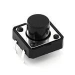
- Push button == > $ 2.50
Total cost of the project is about $30.
This project is divided into three parts. First, we use Heroku to create an app and link GitHub with Heroku. Second, we build an Amazon Alexa skill to implement our work (most important part). Third, we setup our hardware and program it using Arduino IDE.
1. Link Heroku with GitHub
Heroku is a cloud platform as a service (PaaS) supporting several programming languages that is used as a web application deployment model.
First, go to heroku site create a new account or login there. Link is given: https://www.heroku.com/
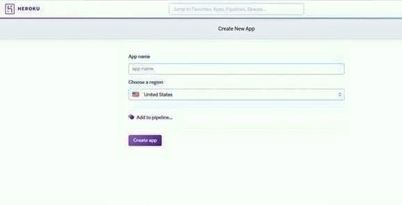
Let's start with creating a new app. I have given my app the name "iottempswitch".
Once the app is made go to GitHub: https://github.com/
Login there or signup if you do not have an account. Once logged in, create new repository.

When you click, you will see page like this.
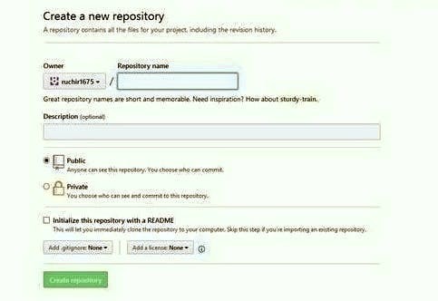
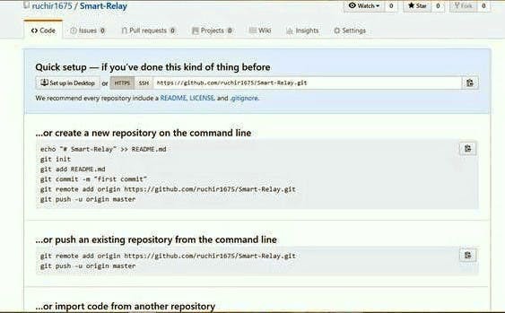
Give any name you want to choose and then press create repository. After that you will see page like this.
On this page, click on README and you will see page like this.
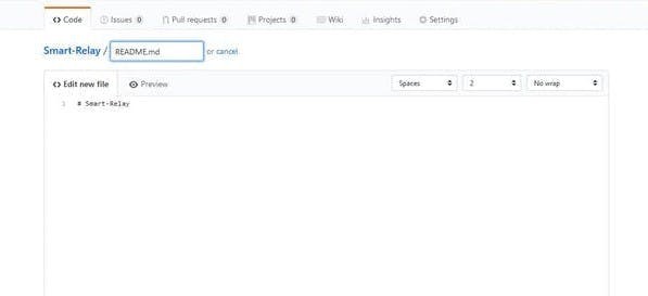
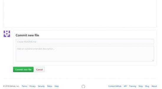
On this page, give the description you want to share with others. After that, click on commit new file.
Next, click on upload button. You will see a page like this.
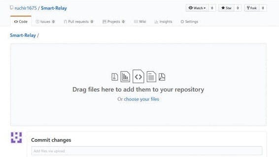
There are two options: either you drag-and-drop the folder or choose the file. Download the required files from below.
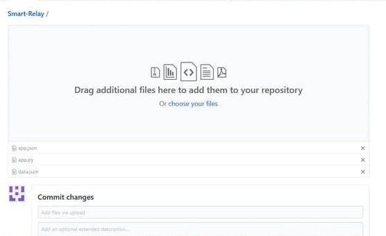
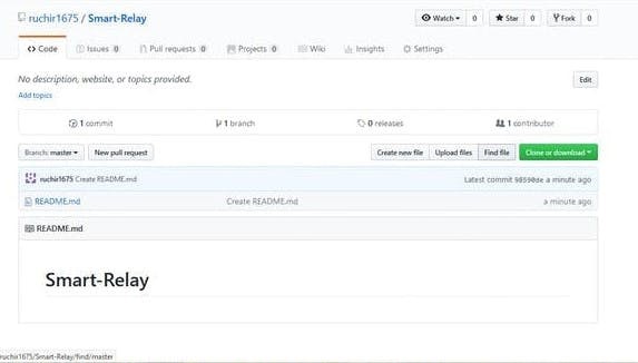
After selecting the files, press commit changes. You will see page like this.
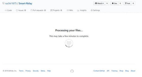
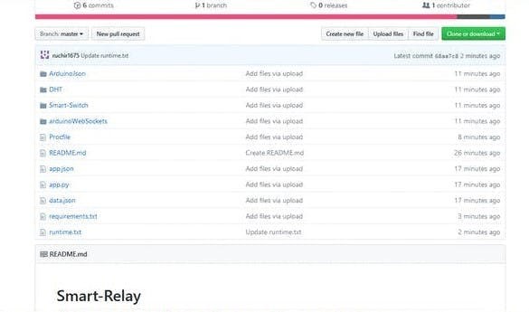
Once done, it will look like this.
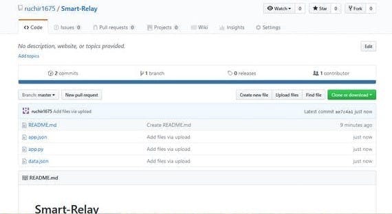
Next we upload three libraries. Click again on the upload file, upload the required files.
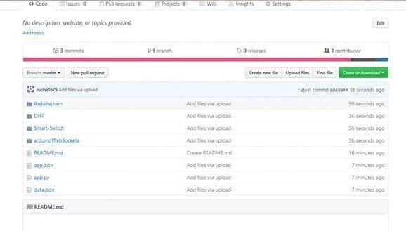
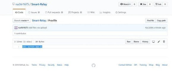
Create a new file, name it Procfile and write web: python app.py. After that commit it.
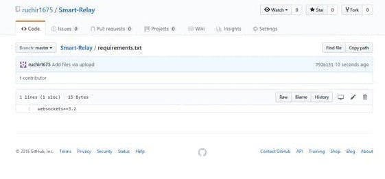
Create new file, name it requirements.txt and write websockets==3.2.
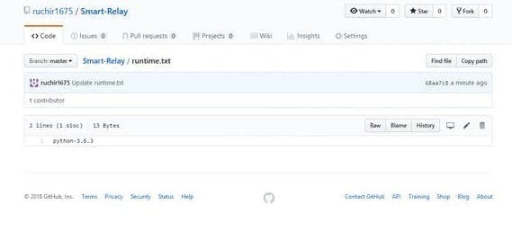
Create new file, name it runtime.txt and write python-3.6.3 or python-3.6.4
Open app which you created at Heroku then go to deploy section.

Click on GitHub you will see like this.
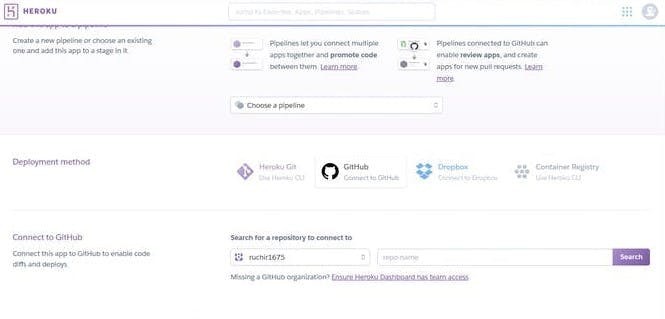
Give repository name which you created at GitHub side. In my case it is Smart-Relay. Copy that and paste it here. You will see like this.
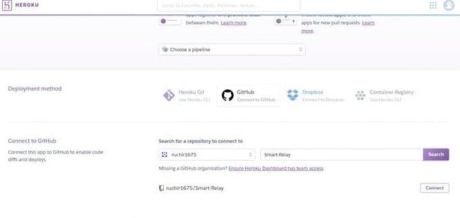
Once your link is shown click on connect. You will see like this.
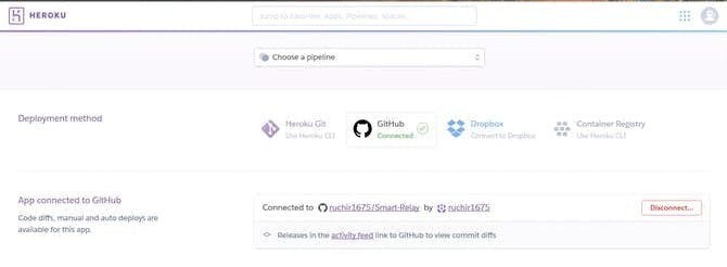
Next, click on deploy branch.
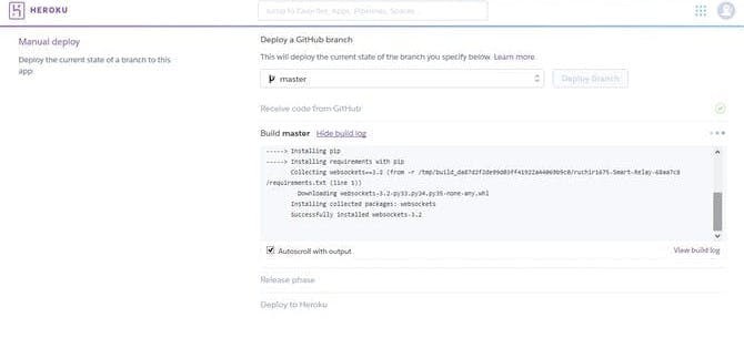
After completing deploy you will see like this.
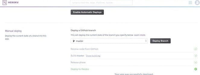
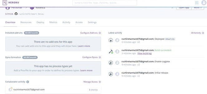
Now, we have created our app successfully. Go to setting and use this link for Amazon and Arduino program.
We have successfully linked Heroku with Github.
2. Amazon
On Amazon Developer site we use Amazon skill to control switch trigger by setting temperature and humidity.
- Go to Amazon Developer Site. Link is given: https://developer.amazon.com/
- Go to Developer console.

- Go to Alexa then select Alexa Skill Kit and then create new skill by clicking on Add new skill. When you add new skill you will see skill information page.
1. Skill Information
We have to provide skill type, language, name.
- It will ask for skill name and language.
- Name ==> Select any name.
- Language ==> Choose according to your region or country.

- On next page it will ask for skill type, there are three skill type namely custom, flash briefing, smart home.
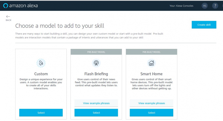
- Skill type ==> select custom.
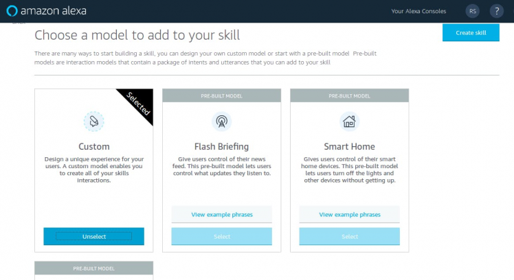
After that you will see a page like this.
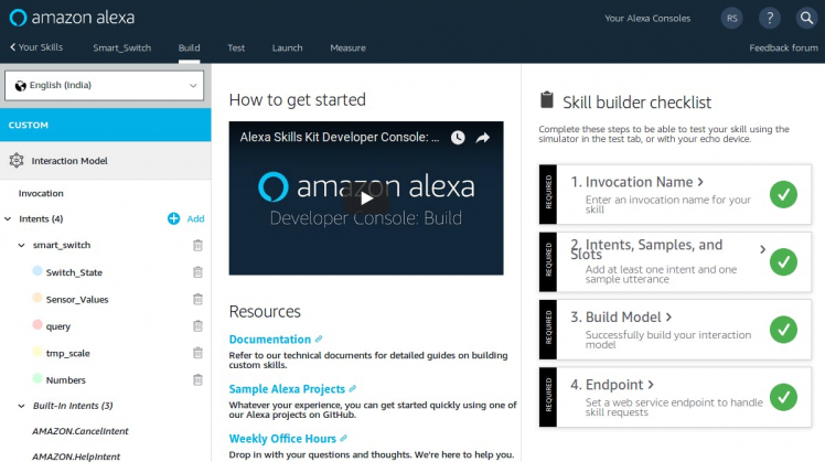
2. Interaction Model
Now invocation name comes under interaction model before it comes under skill information.
- Go to invocation section and give any you want to use.
- Invocation name ==> which you use while communicating with Alexa.
For example: Alexa, ask sensor to turn switch trigger on or Alexa, ask light on, here invocation names are sensor and light.

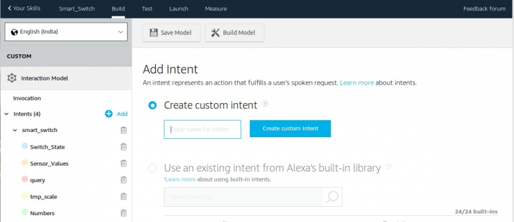
- Firstly, we create new intents. Click on Add (on left hand side) and give any name you want I used "smartswitch". After that add slots type.
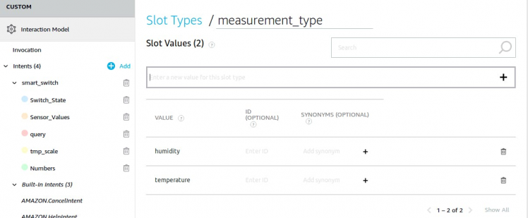
- Give slot type name "measurement_type" and slot values "temperature" and "humidity".
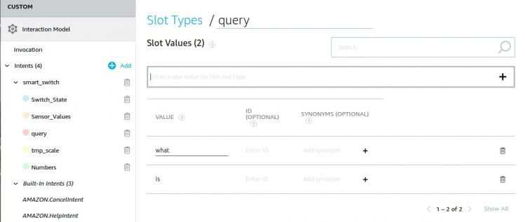
- After that add slot type name "query" and slot values are "what" and "is". It will look like this.
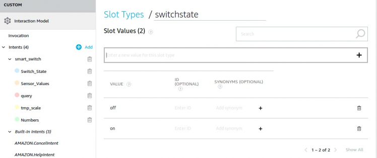
- After that add slot type "switchstate" and slot values are "on" and "off".
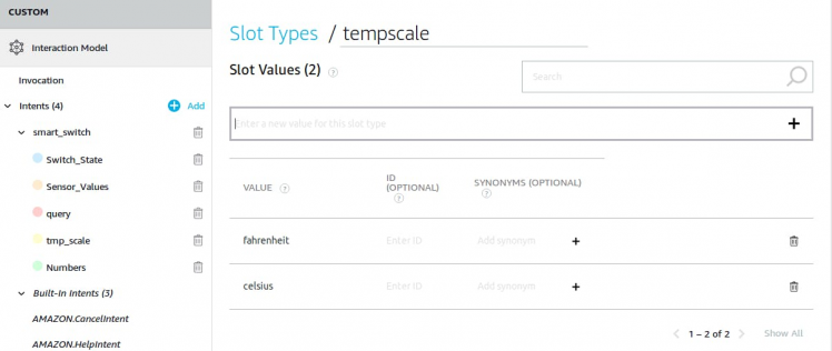
- Add another slot type "tempscale" and slot values are "fahrenheit" and "celcuis".
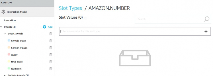
- After that add new slot type here we use existing slot type for that we have to click on use existing slot.In existing slot search for amazon.number and select this and add it. After adding it you will see it in slot types.
So we are done with slot types; in total, we are using 5 slot types. Now, move to the next step.
Click on intent which we created, in my case it is smartswitch. At the bottom you will see intent slot.
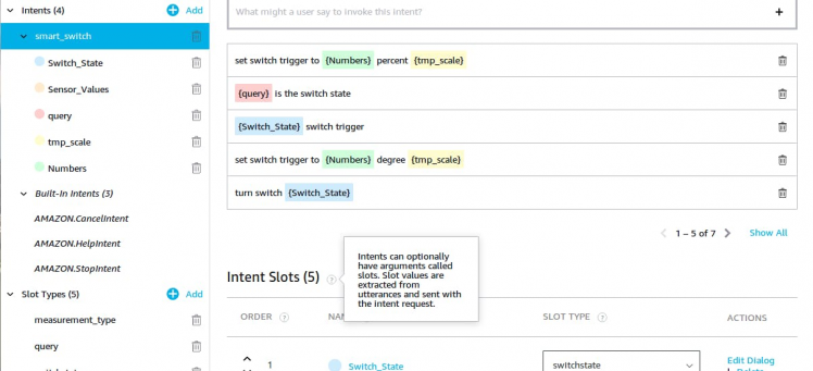
- Create a new slot, give it name "Switch_State" and map it to "switchstate" by using drop down button.
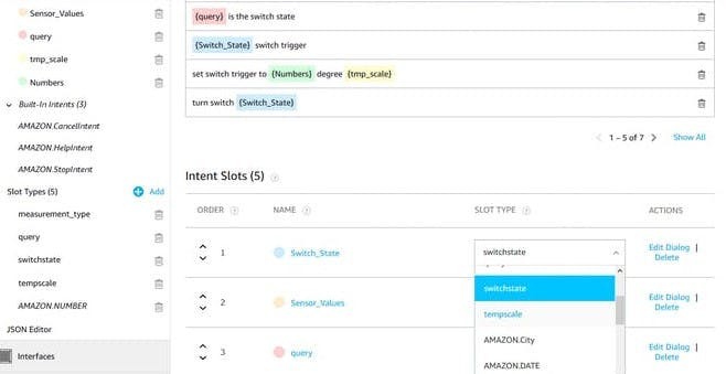
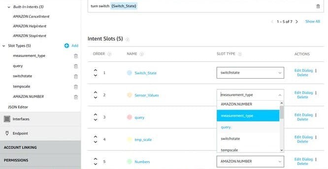
- Create new slot, give it name "Sensor_Values" and map it to "measurement_type".
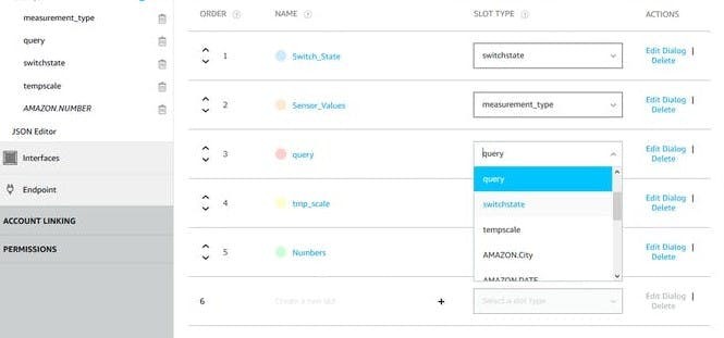
- Create new slot, give it name "query" and map it to "query".
- After that create new slot "tmp_scale" and map it to "tempscale".
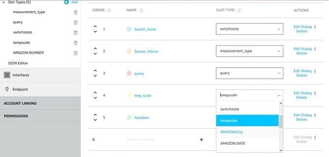
- Create new slot "Numbers" and map it to "Amazon.Number".
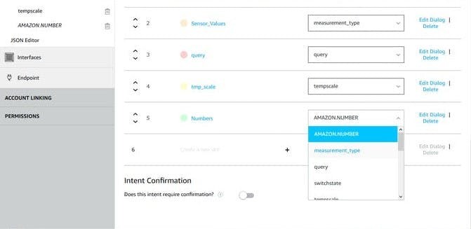
Now we are done with Intent slots. We are using 5 intent slots. After this we move to Sample Utterances.
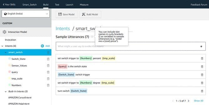
Add this sample utterances.
set switch trigger to {Numbers} percent {tmp_scale}
{query} is the switch state
{Switch_State} switch trigger
set switch trigger to {Numbers} degree {tmp_scale}
turn switch {Switch_State}
{query} switch {Switch_State}
{query} is the current {Sensor_Values}
After this save model and build it.
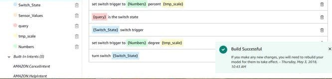
Wait for model to be build after that click on configuration.
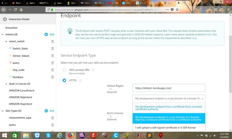
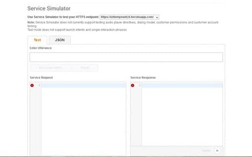
3. Endpoint
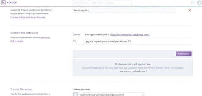
Select HTTPS and add link which was generated while creating Heroku app. In my case it is https://iottempswitch.herokuapp.com/. After adding link, for SSL certificate select second option and click on next.
Good going, we have successfully created our custom skill.
3. Arduino
For ESP8266
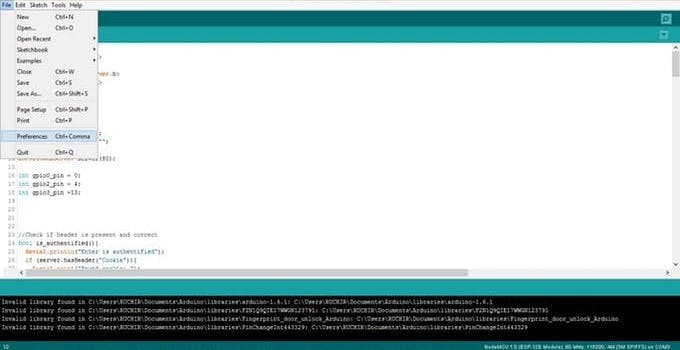
Step 1
- Open Arduino IDE.Then go to File ==> Preference.
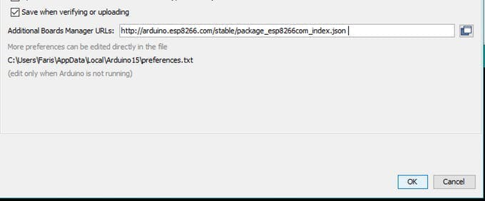
Step 2
- In Additional Boards Manager, copy and paste the URL and click ok: http://arduino.esp8266.com/stable/package_esp8266com_index.json
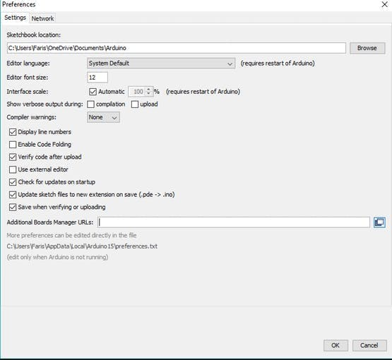 Preferences Page
Step 3
- Open Board Manager by going to Tools ==> Board ==> Board Manager.
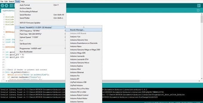
Step 4
- Open Boards Manager and search for nodemcu.
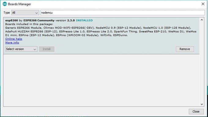 Board Manager Page
Step 5
After that download ESP8266WiFi library.
- Open library Manager : Sketch ==> Include library ==> Manage Libraries.
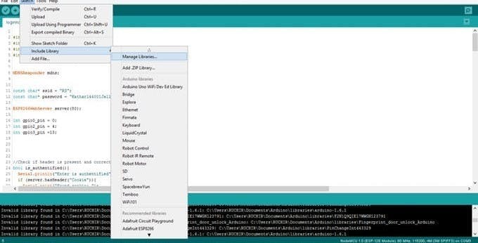
Step 6
- Search for ESP8266WiFi library:
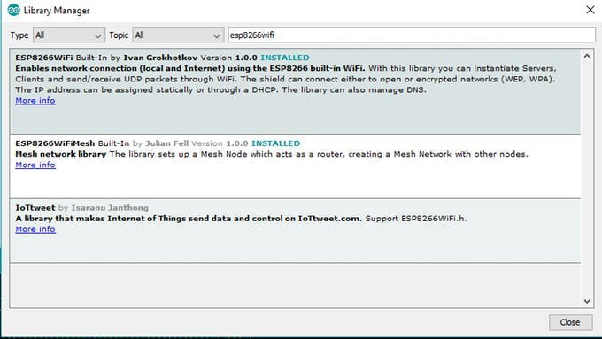 Library Manager Page
Step 7
- Select board ==> Generic ESP8266 Module.

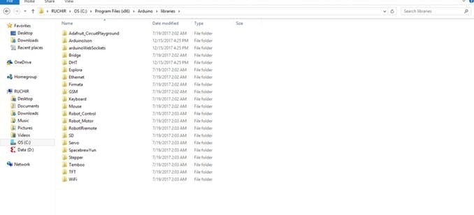
- Before uploading the code we need three libraries: Libraries
Move these libraries to the libraries folder of Arduino.
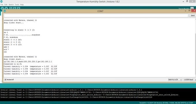
You have to change three things in code SSID, PWD and your heroku app link. After that upload the code. For ESP modules you have to press flash button while uploading the code and then press reset button one time and then release the flash button.
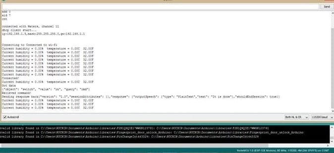
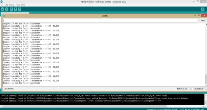
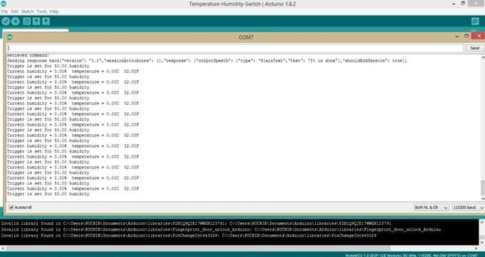
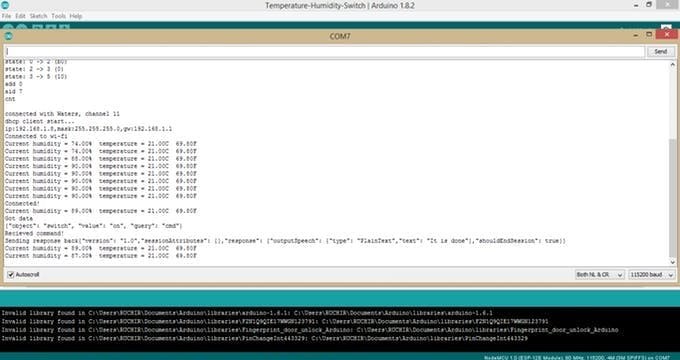
After uploading the code, open the terminal. you will see output.
4. Component Description
1. Relay
Relay is an electromagnetic device which is used to isolate two circuits electrically and connect them magnetically. They are very useful devices and allow one circuit to switch another one while they are completely separate. They are often used to interface an electronic circuit (working at a low voltage) to an electrical circuit which works at very high voltage. For example, a relay can make a 5V DC battery circuit to switch a 230V AC mains circuit.
How it works
A relay switch can be divided into two parts: input and output. The input section has a coil which generates magnetic field when a small voltage from an electronic circuit is applied to it. This voltage is called the operating voltage. Commonly used relays are available in different configuration of operating voltages like 6V, 9V, 12V, 24V etc. The output section consists of contactors which connect or disconnect mechanically. In a basic relay there are three contactors: normally open (NO), normally closed (NC) and common (COM). At no input state, the COM is connected to NC. When the operating voltage is applied the relay coil gets energized and the COM changes contact to NO. Different relay configurations are available like SPST, SPDT, DPDT etc, which have different number of changeover contacts. By using proper combination of contactors, the electrical circuit can be switched on and off. Get inner details about structure of a relay switch.
The COM terminal is the common terminal. If the COIL terminals are energized with the rated voltage, the COM and the NO terminals have continuity. If the COIL terminals are not energized, then the COM and the NO terminals have no continuity.
The NC terminal is the Normally Closed terminal. It is the terminal that can be powered on even if the relay doesn't receive any or sufficient voltage to operate.
The NO terminal is the Normally Open terminal. It is the terminal where you place the output that you want on when the relay receives its rated voltage. If there is no voltage to the COIL terminals or insufficient voltage, the output is open and receives no voltage. When the COIL terminals receive the rated voltage or a little under, the NO terminal receives sufficient voltage and can turn on the device on the output.
2. DHT temperature sensor
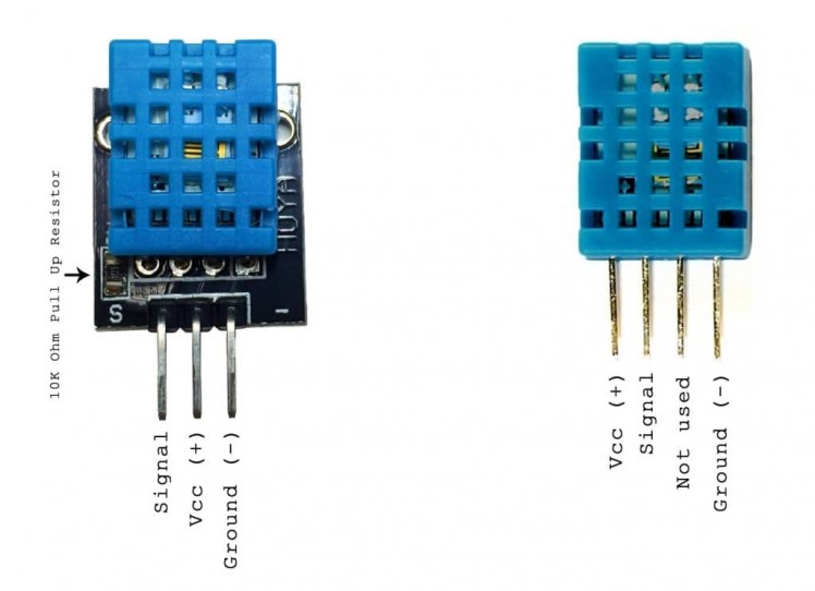 DHT11 Temperature Sensor
DHT11 is a Humidity and Temperature Sensor, which generates calibrated digital output. DHT11 can be interface with any micro controller like Arduino, Raspberry Pi, etc. and get instantaneous results. DHT11 is a low cost humidity and temperature sensor which provides high reliability and long term stability.
3. ESP8266 Complete Description
The ESP8266 WiFi Module is a self-contained SOC with integrated TCP/IP protocol stack that can give any microcontroller access to your WiFi network. The ESP8266 is capable of either hosting an application networking functions from another application. Each ESP8266 module comes pre-programmed with an AT command.
The ESP8266 supports APSD for VoIP applications and Bluetooth co-existence interfaces, it contains a self-calibrated RF allowing it to work under all operating conditions, and requires no external RF parts.
Features
- 802.11 b/g/n
- Wi-Fi Direct (P2P), soft-AP
- Integrated TCP/IP protocol stack
- Integrated TR switch, balun, LNA, power amplifier and matching network
- Integrated PLLs, regulators, DCXO and power management units
- +19.5dBm output power in 802.11b mode
- Power down leakage current of <10uA
- 1MB Flash Memory
- Integrated low power 32-bit CPU could be used as application processor
- SDIO 1.1 / 2.0, SPI, UART
- STBC, 1×1 MIMO, 2×1 MIMO
- A-MPDU & A-MSDU aggregation & 0.4ms guard interval
- Wake up and transmit packets in < 2ms
- Standby power consumption of < 1.0mW (DTIM3)
Pin Diagram and Pin Description
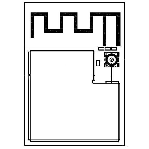
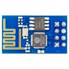 ESP8266 Module
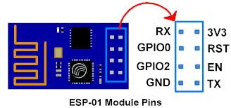 ESP8266 Pins
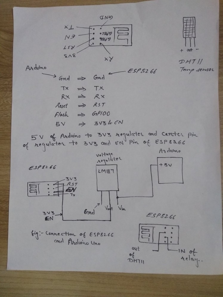
For connecting ESP Module with Arduino UNO we need Lm117 3.3 voltage regulator or any regulator because Arduino is not capable of providing 3.3 v to ESP8266.
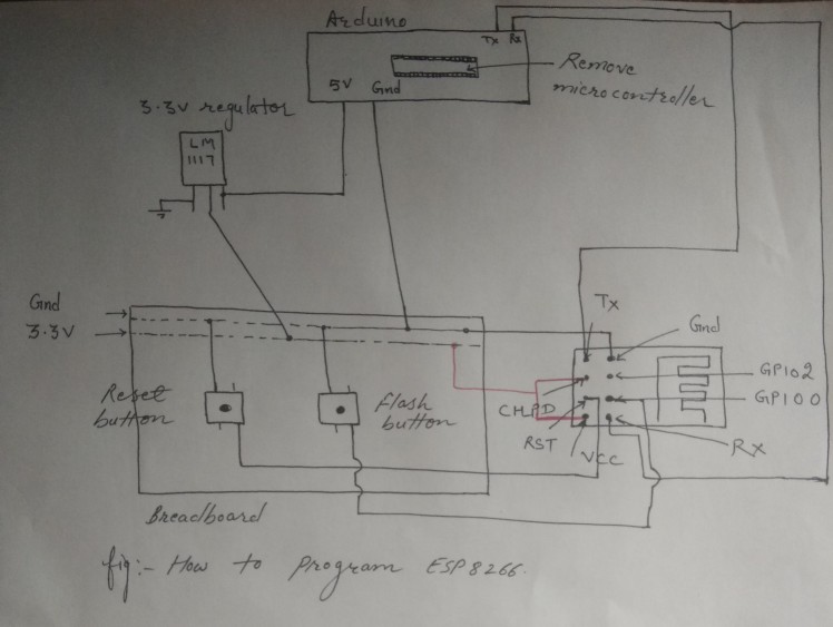 How to program ESP8266 using Arduino Uno
Note: While uploading the code press flash button and then press reset button one time and then release flash button.
 How to program ESP8266 using Arduino Uno
For connecting DHT11 sensor and relay we use two GPIO pins of ESP8266 Module. After uploading the code you can disconnect the RX, TX, GPIO0 pins.
I have used GPIO0 for DHT11 sensor and GPIO2 for relays. DHT11 sensor works fine with ESP8266 but for relays we need one extra thing, i.e, opto isolator or opto coupler.
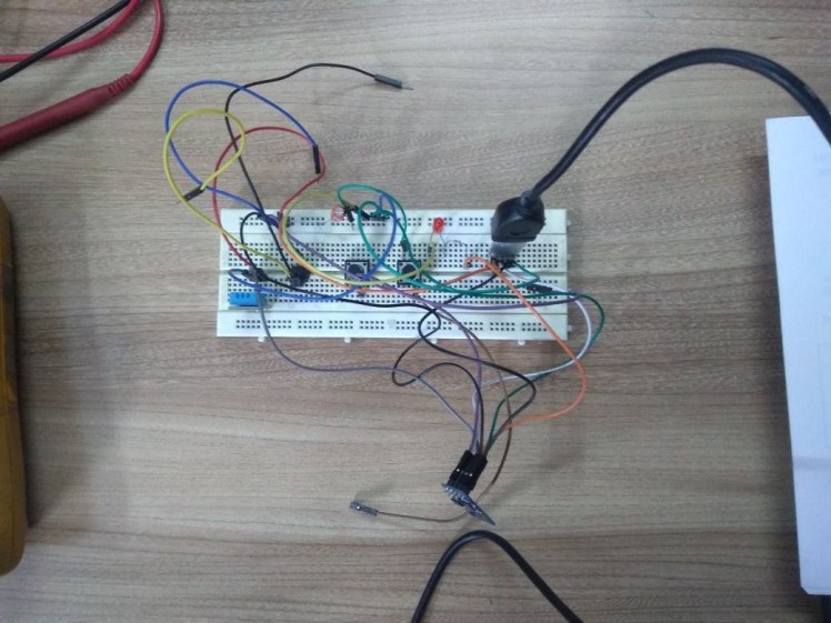
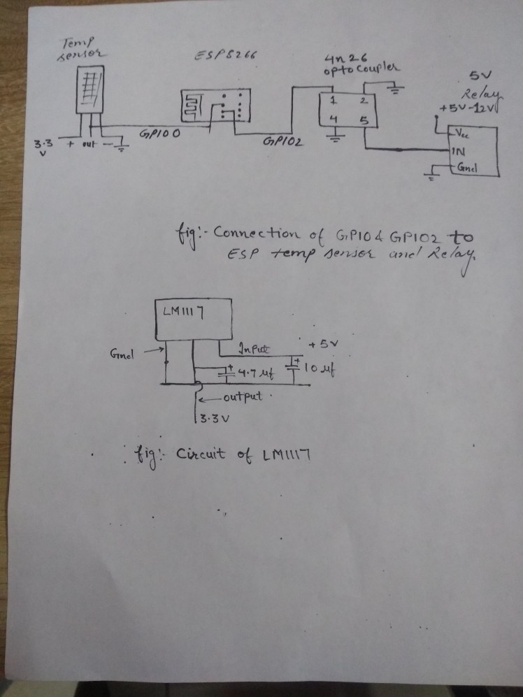 How to connect ESP8266 with DHT11 , Relay and connection of 3.3v Regulator
 Connection of 3.3V Regulator with ESP8266 and Arduino Uno
 3.3V Regulator
 3.3V Regulator
5. Connections
ESP8266 === > DHT11
- GPIO0 === > Output pin
ESP8266 === > Relay
- GPIO2 ===> Input
ARDUINO ===> ESP8266
- Gnd ===> Gnd
- TX === > TX
- RX === > RX
- Reset Button === > RST
- Flash Button === > GPIO0
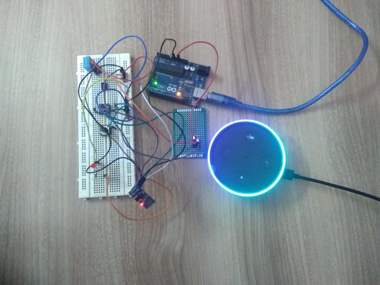
6. After setup all the thing
We have successfully created our app, skill and our hardware is ready. So, its time to check.
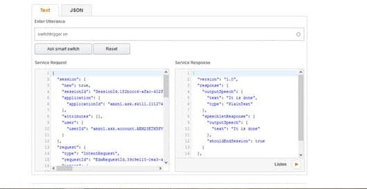
For that your ESP8266 is powered on because our server is running on ESP8266. Here I have not connected any sensor to ESP8266 I am just checking whether its working or not but you can connect sensor, relay to ESP8266. Once it is connected to Heroku you will see connected. For testing go to Amazon skill which you created, then click on test page. Once it is verified its working I will connect my sensor to ESP8266. You can see results as shown below in Result section.
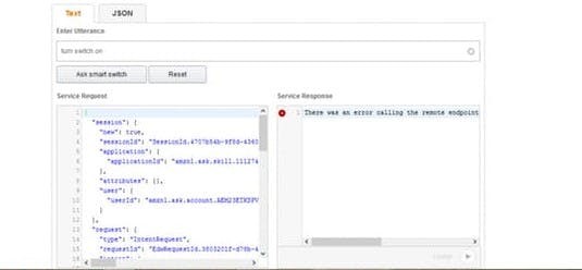
If you use it without connecting ESP8266 you get this error.
Utterance you can use
- set switch trigger to {Numbers} percent {tmp_scale}
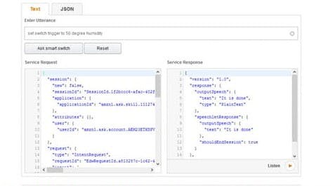
ex. set switch trigger to 50 percent humidity
- {query} is the switch state
ex. on/off is the switch state
- {Switch_State} switch trigger
ex. on/off switch trigger
- set switch trigger to {Numbers} degree {tmp_scale}
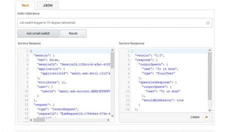
ex. set switch trigger to 76 degree fahrenheit
ex. set switch trigger to 24 degree celcius
- turn switch {Switch_State}
ex. turn switch on/off

Note: In this we are able to control the appliances like A.C, Fan, Cooler etc by setting or selecting appropriate temperature.
For example, A.C is connected to relay and we set temperature 24 degree Celsius once temperature is rising above that, temperature sensor will detect and turn ON the A.C. When temperature is maintained, it will again switch it off the A.C.
7. While talking to Alexa
- Alexa, ask arduino to turn switch trigger on/off
- Alexa, ask arduino to set switch trigger to 24 degree celsius.
- Alexa, ask arduino to set switch trigger to 50 percent humidity.
- Alexa, ask arduino to turn switch on/off
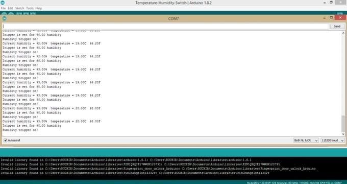
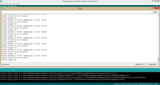
Results
Temperature and humidity reading.
Set trigger to 90 percent humidity.
Set trigger for 21 degree celcius.
VUI Diagram
 Voice User Interface Diagram
DEMO VIDEO
1. Set trigger for temperature and humidity (using Arduino)
2. Set trigger to 20 degree celsius (using Arduino)
3. Set trigger to 80 percent humidity (using Arduino)
File needed for GitHub. Please download from link given below.


Leave your feedback...