
Smart Porch Light Project: Digi’s Xbee Lte Cellular Module

Made by Arakiel / Home Automation / Lights / Sensors
About the project
For this project, we have combined Digi International’s Cellular LTE XBEE module with an Arduino Mega-2560 to give us access to a cellular network for use with an automated porch light.
Project info
Difficulty: Difficult
Platforms: Arduino, Seeed Studio, Ubidots, XBee
Estimated time: 2 weeks
License: GNU General Public License, version 3 or later (GPL3+)
Items used in this project
Hardware components
![Grove - Relay [Seeed Studio] 103020005 Grove - Relay](https://www.mouser.co.uk/images/seeedstudios/images/103020005_SPL.jpg)
![UV Sensor [Seeed Studio] 101020043 UV Sensor](https://www.mouser.co.uk/images/seeedstudios/images/101020043_SPL.jpg)

![Grove - Tempture and Humidity Sensor [Seeed Studio] 101020074 Grove - Tempture and Humidity Sensor](https://www.mouser.co.uk/images/seeedstudios/images/101020074_SPL.jpg)

![Expansion board [Seeed Studio] 103030000 Expansion board](https://www.mouser.co.uk/images/seeedstudios/images/103030000_SPL.jpg)


View all
Story
Step 1: Gathering The Devices
Ideally, the information and provided links should be sufficient for anyone to build a cellular IoT sensor node. The project is intended for those who have familiarity with the Arduino development platform and some experience in programming.
For this project, you will need the devices outlined below:
- The XBee Cellular kit with LTE Module and an interface board
- The Arduino Mega with suggested power supply
- The sensors and interface shield outlined in the overview
- An account with Ubidots Cloud Service at https://ubidots.com
Optionally you may wish to purchase a UART communication cable not included in the project BOM:
Of course, as with any project, other components can be used depending on need. Digi International has several additional cellular modules available for you to choose from based on your project requirements:
- Digi International XBee® Cellular 3G Global Embedded Modem
- Digi International XBee® Cellular LTE-M Embedded Modem
- Digi International XBee® Cellular NB-IoT Embedded Modem
The example software for the Arduino Mega-2560 is stored on GitHub (Mouser XBee Cellular GitHub Repository). This will require the installation of the Arduino IDE to interface and upload the code to the Arduino Mega. You can download the IDE using the following link: Arduino IDE Software. You will need to ensure you have installed any required libraries that may not be included with the IDE such as the Temp/Humidity sensor library (Seeed Studio Temp/Humidity Library
). If this is your first time installing third party libraries in the IDE, please refer to the Arduino tutorial linked here (Arduino Library Guide).
Step 2: Setting Up The Digi XBee Module
The XBee module can be set up easily using the XCTU software offered by Digi International. The kit for the LTE module provides you with a development base that will allow the XCTU software to interface and change the module settings (Figures 2a and 2b). To connect to your cloud service, you will need to make several setting changes as well as a possible firmware update. If you do not currently have the software installed, you can find and download it using this link (Digi XCTU Software Link). Each XBee module will come activated with 6 months of free cellular service through Verizon. Though we have not had an opportunity to use any of the other available Digi Cellular modules, the setup process for each should, in theory, be identical.
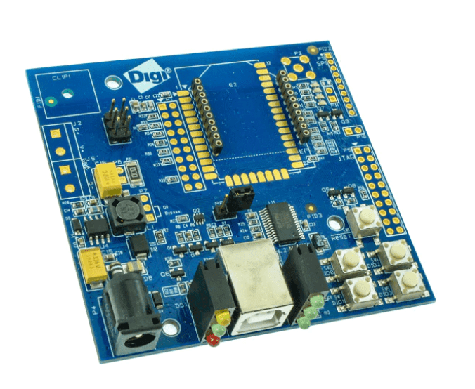
Figure 2a: The Digi XBee development base.
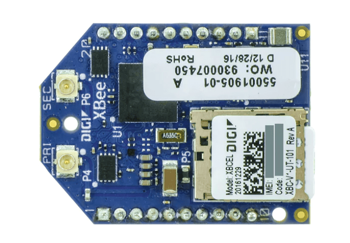
Figure 2b: The Digi XBee LTE Module.
Adding The XBee Module
The first time you open the XCTU software, you will need to add the XBee module from the Radio Module List on the left side of the screen by clicking the module outline with the (+). A pop up will ask for the correct COM port which can be verified in your system's device manager. Once you review the COM settings and select OK, the software will scan for available devices. Select the correct device from the list on the left and click “read” to import the current settings from the module as shown in Figure 3. If the device firmware needs updating, you may need to perform this action at this time.
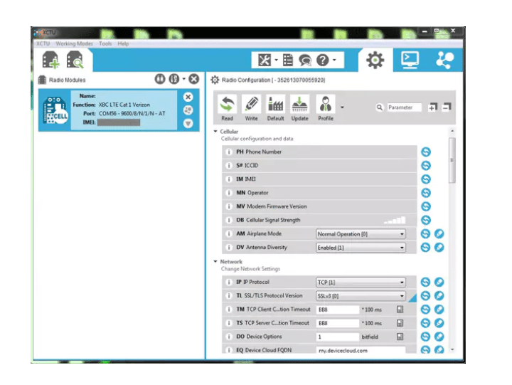
Figure 3: Using the XCTU dialog box, you’ll add the XBee module by clicking the plus sign (+).
Configuring The XBee Module
For the module to connect and send data to the Internet, you must configure it for TCP mode, update the destination address with the IP or web address of your cloud service, and set your destination port. In most cases, the destination port will be 80 and need conversion to the hex value 50. If this is not the correct port, verify and update it with the one needed by your selected cloud service remembering to convert first. Once you have made all the proper changes, refresh the device by clicking the write icon at the top of the software screen. Once the module is configured, remove it from the development board and insert it carefully into the XBee shield, paying attention to polarity.
For additional information or specific instructions on how to connect and modify the LTE module, or use of the XCTU software, please refer to the following links (Digi XBee® Cellular LTE Cat 1 Documentation) and (XCTU Configuration and Test Utility Software Documentation). To make things easier we have also included a configuration file for the XBee module on the project GitHub page you can use to import pre-configured settings to the module.
Setting Up The Sensor ShieldIn addition to the XBee shield, you will also use the Seeed Studio Base Shield (Figure 4) that allows easy plug-in of multiple sensor modules. Before continuing, ensure that the switch on the shield is set to 5V for proper function. Attach the five devices, the temperature/humidity to the I2C, ambient light and UV to the analog, and relay to the digital.
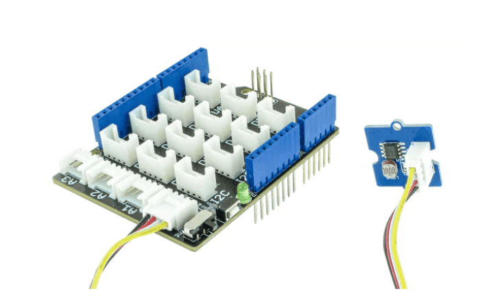
Figure 4: Sensor shield with ambient light sensor in port A0.
It is important to note which analog and digital ports you are using since they will need updating in the provided Arduino code to match. The I2C connection will work regardless of which I2C port is used. Once you have completed assembly of the shield, plug the base shield into the Arduino.
Step 3: Setting Up The Arduino Code/REST API
The provided Arduino code uses RESTful or REST API to communicate over HTTP to post or get data from the cloud. For this example, we will be using Ubidots as our cloud service. Data from the sensors is communicated over a serial port from the Arduino to the XBee, which is then transmitted over the cellular network. The Arduino Mega-2560 has only one available serial port to interface with the XBee shield and may need the creation of a second virtual port using the SoftwareSerial function in the Arduino code. This is not required for the code to function but does make visualization through a serial monitor easier if you want to check progress.
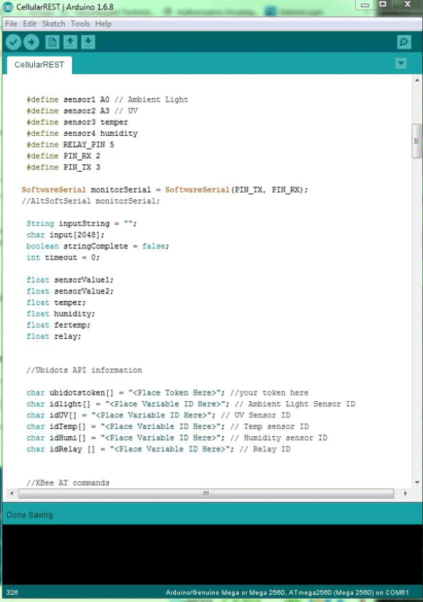
Figure 5: Arduino IDE.
The program begins by issuing a series of AT commands to the XBee module to verify the correct configuration and connection to the cell network. Once the program confirms a network connection, it will send a generic POST to the cloud service to verify communication. If successful, the server will return with a response such as 200 or 201, which will be output to the SoftwareSerial port seen in Figure 6. Data is transmitted and received through the Serial function and displayed using the MonitorSerial configured through the SoftwareSerial mentioned previously and shown in Figure 6. Data from the sensors is uploaded as the software cycles through each sensor function call on a 5-second delay to give enough time for a response from the server.
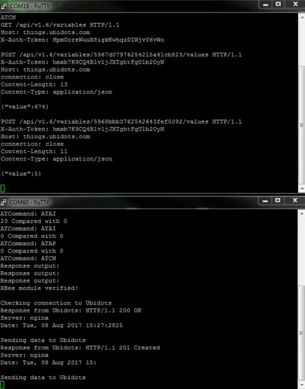
Figure 6: Putty Terminal Window
As previously said, you need to make changes to the code for the software to perform correctly. Some may not be necessary, but things such as changing the API token and Variable IDs will be required. Depending on how you chose to configure the sensor shield or which pins you identify on the XBee shield for the RX and TX lines, it is important to update these prior to uploading your code to the Mega.
Step 4: Setting Up The Ubidots Dashboard
This example uses cloud services offered by Ubidots for data storage as well as dashboard creation as shown in Figure 7. If you have not used the service prior, you will need to create an account with them. The service uses a point-based system which I have found for those starting out to be very user-friendly and offers many tutorials and guides to aid in setup for several different development platforms. Create your account, giving all required information, and take time to read the documentation tab that talks about REST and MQTT as well as helping to find your API token for use in your code.
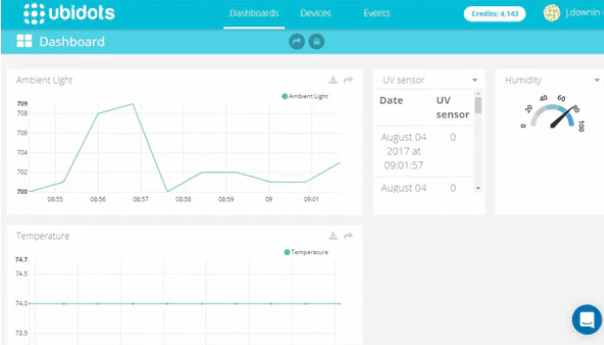
Figure 7: Ubidots dashboard.
The API token is automatically generated once the account is created. However, the Variable IDs will need to be set up from the devices tab. From the devices, tab click the Add Device icon in the screen and give a name to your project. You will see a flag appear across the top of the screen once the device has successfully been created. Click on the newly created device which takes you to a new screen from which you can create all the required variables. You will need to add a new variable for each sensor used in this project in the same method used to create the device, selecting default for each. As with the device creation, you will see a banner appear across the top showing each variable was successfully created. Click the newly created variable; the variable ID can be found on the variable screen along the left-hand side.
Step 5: Programming And Running The Code
Once you have updated the code downloaded from the GitHub repository with the correct API and variable token as well as verifying or changing the Analog and Digital input pins, you are ready to program and run your code. Please note that while the XBee shield is connected to the Mega, any attempt to upload code from the Arduino IDE will fail. Should you need changes to the code, remove the XBee shield and replace once programming is complete. As with most Arduino products, the code will begin running as soon as the programming is complete. Once finished, remove the USB cable, attach the XBee shield, and apply power (Figure 8).
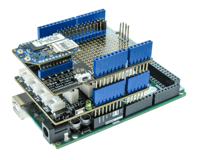
Figure 8: Arduino Mega, Sensor Shield, XBee shield, and Digi LTE Module stacked.
You can view the commands supplied to the XBee module through the Arduino IDE output monitor. If you wish to see the response output, you will need to provide a second serial connection. Two possible solutions are purchasing a USB to serial cable that provides a breakout, such as part number 895-TTL-232R-RPI, or using another Arduino, such as the UNO, with the Atmel chipset removed. This, of course, is not necessary but does allow you to verify everything functions appropriately.
As soon as the program begins running and verifies a network connection, you should start to see data available on your Ubidots account. Now you can create a Dashboard to view and share the data in any number of formats. Ubidots has several tutorials available that show use of the dashboard and creation of events (Ubidots Getting Started).
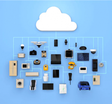
This project demonstrates one possible use for a basic IoT solution in the hope of sparking creativity. From home security and automation to agriculture and smarter cities, IoT can provide us access to information faster and easier. Of course we would love to see what other concepts and projects you come up with, along with any feedback you might have. Please share your projects and ideas at Facebook, Twitter, or Google+.
Code
Credits
Related products


Leave your feedback...