
Smart Mailbox
Made by Mouser Electronics / Home Automation / Notifications / Sensors / IoT
About the project
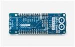
In this project, we will create an easy LPWAN (low-power wide-area) application. By using an Arduino MKRFOX 1200 board and the Sigfox network, the post box will send a notification, whenever a letter arrives.
Project info
Difficulty: Easy
Estimated time: 2 hours
License: GNU General Public License, version 3 or later (GPL3+)
Items used in this project
Hardware components

View all

Story
Tired of going to your post box every day for checking for mail and finding at the end it is empty? In this project, we will create an easy LPWAN (low-power wide-area) application, which will connect the postbox to the cloud. By using an Arduino MKRFOX 1200 board and the Sigfox network, the post box will send a notification, whenever a letter arrives.
What is Sigfox?
Sigfox is a LPWAN (low-power wide-area) network that provides connectivity for the IoT (Internet of Things). Applications that need to send small and infrequent data are a great fit to use the Sigfox network. It allows you to send 140 messages per day with each message can carry a payload of 12 bytes. As it is a LPWAN network, the power consumption is very low, which makes it ideal for battery-operated applications.
Let's get started!
Step 1: Hardware setup
We've listed all the needed parts in the bill of materials (BOM) that will be used in this project. We have included a battery pack and battery holders; from which you only need one of them. In this tutorial we`re going to use the battery holders with 2x AA batteries to power the board.
The assembly of all hardware parts is very simple:
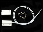
- Connect the magnetic contact switch to Arduino (the order of the wires doesn't matter):
- One wire of the sensor to PIN 1 (yellow jumper)
- Second wire of the sensor to GND pin (black jumper)
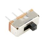
- As the MKRFOX 1200 doesn't have a power ON/OFF switch onboard, we will add an SPDT slide switch to be able to switch the board off if needed. Before connecting the battery holders, solder the SPDT switch on the power/voltage wire (red wire).
- Connect the battery holders to the screw terminal block.
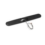
- Attach the antenna to the micro UFL connector.
For more details on how everything is connected, check the 'schematics' section down below.
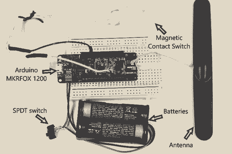
Figure 1: All the hardware parts hooked up together
Step 2: Software setup
If it is your first time to use the Arduino MKRFOX 1200, the board must firstly be configured and registered to the Sigfox network. If you already did this, you can skip to Step 4.
- Install the Arduino IDE on your PC (available to download from Ardunio’s website).
- Open the Arduino IDE and click on: Tools > Boards > Boards Manager then install the Arduino SAMD Boards (32-Bits ARM Cortex-M0+) package
- Click on Sketch > Include Library > Library Manager then install these libraries:
- Arduino MKRFOX 1200
- Arduino Low Power
- Connect your board to your PC and open the "FirstConfiguration" example which you'll find under: File > Examples > Arduino SigFox for MKRFox 1200.
- Flash the code on your board and open the serial monitor.
- Copy the ID and PAC numbers that are printed in the serial monitor, which will be used to register the board to the Sigfox network (Figure 2)
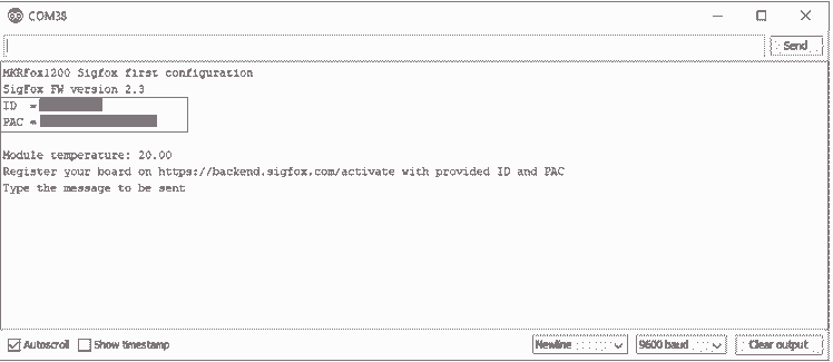 Figure 2: ID and PAC of the Arduino board
Step 3: SigFox backend - board registration
The next step, you'll need to register your board to the SigFox network. Navigate to the SigFox backend and follow the steps there to register your board. You'll be asked to enter the ID and PAC numbers, which you should have copied in Step 2.
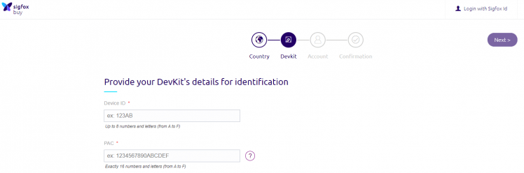
Figure 3: Board registration on SigFox backend
Step 4: Code
Now that everything is set up, flash the smart_mailbox.ino code, which you’ll find down below in the code section. The Arduino is programmed to be in sleep mode, until an event occurs. This event is triggered, whenever the mailbox lid gets opened. I'll go through now on some of the main points in the provided code.
- In the Interrupt function a variable is added to read the battery voltage, which we’ll use to calculate the remaining battery percentage. This calculation is a roughly estimation of the battery state of charge. Ideally a battery charging circuit (like this) is needed to be able to calculate the battery capacity, which we can then use to calculate an accurate state of charge. But for now we will go with the estimation calculation shown in the code below.
- sensorValue = analogRead(ADC_BATTERY);
- // Convert the analog reading (which goes from 0 - 1023) to a voltage (0 - 4.3V):
- // if you're using a 3.7 V Lithium battery pack - adjust the 3 to 3.7 in the following formulas
- voltage = sensorValue * (3 / 1023.0);
- //battery percentage calculation
- // 2.2 is the cutoff voltage so adjust it if you're using a 3.7 V battery pack
- battery_percentage = ((voltage - 2.2) / (3 - 2.2)) * 100;
- If you trigger the Arduino by moving the two magnets away from each other, you should be able to see a LED is blinking on the board. That’s because of the debug functions are enabled but you should disable it after testing to use all the features of the power saving mode.
- // Set debug to false to enable continuous mode
- // and disable serial prints
- int debug = true;
- After disabling the debug functions, maybe you’ll encounter a problem. The Arduino will get triggered only once and never wakes up again. After searching around a bit, there was a thread about the same problem on the Arduino forum, which provided a workaround. The problem is located in the Sigfox library. I changed the sigfox.cpp file according to the thread on the Arduino forum and added the file also in the code section down below. If you face the same problem you’ll have to replace it with the sigofx.cpp file, which is located on your PC in this path: C:/Documents/Arduino/libraries/Arduino_SigFox_for_MKRFox1200/src/. Then reflash your board to update the library on your board.
NOTE: The provided code sends the Arduino module to sleep, which causes the board to be not detected on the COM port. When flashing the board, press the 'RST' button twice, which will make the board be detected.
Step 5: SigFox backend - callback function
In the next step we’ll create a callback function. This callback function will transfer the data that is received from your MKRFOX1200 board to your email address.
- Navigate to the Sigfox backend
- Click on the following: DEVICE TYPE > click on your DevKit > Edit
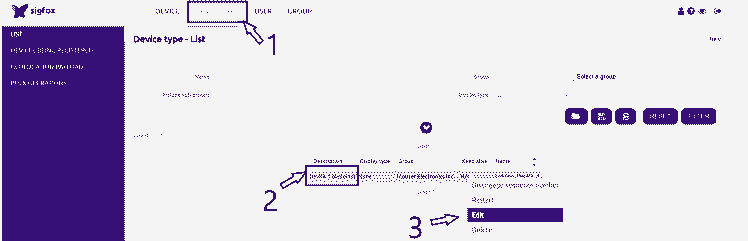 Figure 3: Device Settings
 - You'll be navigated to this this page (Figure 4). Make sure, that Callback is selected under Downlink mode.
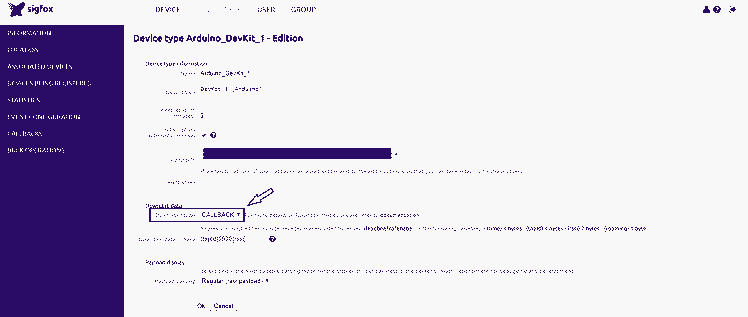 Figure 4: Device Settings - Downlink Mode
 - Click on CALLBACKS, which is located on the left side panel (Figure 4). You'll be navigated to the Callbacks page and then click on New
- Select Custom callback. (Figure 5)
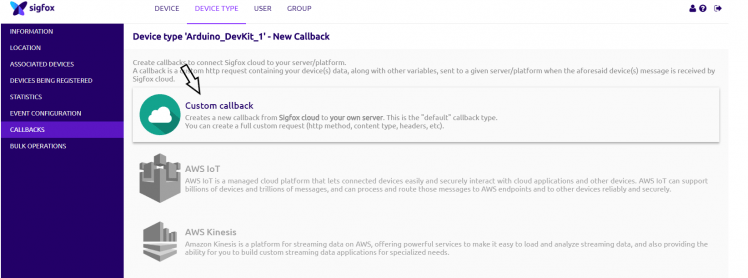 Figure 5: Device Settings - Custom callback
 - In the following we will set up the custom callback function:
- Set the Type > DATA & UPLINK & Channel > EMAIL
- As we will be sending a 1 byte of payload with the remaining battery to the Sigfox server, we have to configure the Custom payload config. The variable 'percentage' is an 8-bit unsigned integer, which will be received to the Sigfox server.
- Lastly, add this variable ‘{customData#percentage} ' in the message body. This will show the received battery percentage in the email.
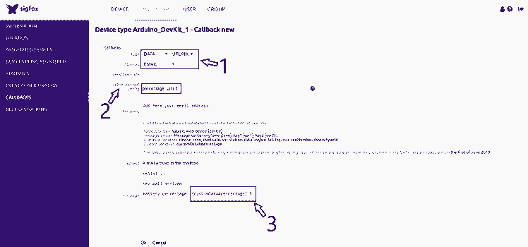 Figure 6: Callback function setup
Step 6: Mounting
In the last step mount all the parts and pieces on your mailbox. All the parts are fixed on the door inside of the mailbox. The magnetic contact switch is fixed on the mailbox lid. The antenna is fixed outside the mailbox. (It is recommended not to stick the antenna on a metal surface.)
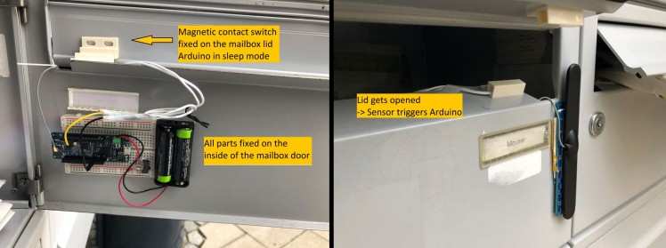
Figure 6: Mounting all parts on the mailbox
Conclusion
Now you have have converted your traditional mailbox to a smart one that is connected to the Cloud.
What's next? This application can be connected to a solar panel, which will recharge the batteries and have a self-powered wireless sensor node.
Thank you for following this tutorial :)
Author
Rafik Mitry joined Mouser in 2019 right after finishing his Master's degree in Electrical Engineering at the Technical University of Munich where he also worked in research in the field of energy harvesting for 3 years. As a Technical Marketing Engineer at Mouser, Rafik creates unique technical content that reflects current and future technology trends in the electronics industry. Besides keeping up with the latest technology trends, Rafik is an avid lover of aviation and tennis.
Schematics, diagrams and documents
Code
Credits
Mouser Electronics
Mouser Electronics is a worldwide leading authorized distributor of semiconductors and electronic components for over 1,100 manufacturer brands. We specialize in the rapid introduction of new products and technologies for design engineers and buyers. Our extensive product offering includes semiconductors, interconnects, passives, and electromechanical components.
Related products


Leave your feedback...