
Simple Wireless Keyboard For Pc

Made by Gyro / 3D Printing / Communication / Music
About the project
Wireless keyboard designed specifically for youtube and Netflix on PC or Mac. Works great with music players like Spotify too.
Project info
Difficulty: Difficult
Platforms: Arduino
Estimated time: 2 weeks
License: GNU General Public License, version 3 or later (GPL3+)
Items used in this project
Hardware components


Story
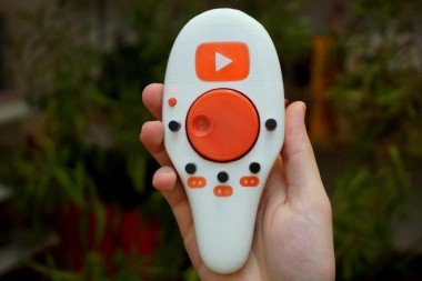
I have my desktop PC meter away from my bed so naturally, I like to watch YouTube and movies from the comfort of my bed. Every time I lay down, however, I find myself needing to adjust volume, pause the video for some reason, or simply skip video entirely. I could just lean forward and hit a button on the keyboard but I'm too lazy to do that so instead, I decided to spend dozens of hours designing and building this remote control for my PC. It's really just wireless keyboard.
I have actually had a wireless keyboard already but it's a keyboard. When the lights are off it's basically impossible to find the key I'm looking for. On top of that with its tiny size, I'm more likely to press three buttons at once than the one I want even with my tiny fingers. But really it's just an excuse to build something cool.


Step 1: Overview
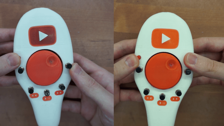
I just want to briefly touch on how this keyboard works. It has two modes. One's for youtube and another for all other media. They both do the same thing. Play, pause, skip, rewind, next, previous and volume adjustment. The only difference is that in the blue/media mode the key presses translate to the default windows media buttons whilst in the red/youtube mode it's translated to the youtube keyboard shortcuts(can be found here). Also, there is no previous button in the red/youtube mode as I found it more convenient to have a fullscreen button instead.
Step 2: Tools and Materials
Tools
- 3D printer
- Soldering iron
- hot glue
materials and electronics
- PLA - or any other preferred material for your 3D printer. White and red colors are essential and black is required some details
- M3 tap and screws
- Rotary encoder I have made in my previous instructable. Right here
- 4x 3mm LEDs. Three red and one blue
- Li-po battery 1s 240mAh
- 11x diodes - 1n4007
- 2x 4k7 resistor
- 9x 100k resistor
- 2x 220R resistor
- 2x 100nF ceramic capacitor
- 5x pushbuttons - PB-11D02
- Toggle switch - KNX-1
- LM7833 voltage regulator
- TP4056 charging board - Link
- Small DC-DC step up converter - CE025 Link
- 2x NRF24L01 RF transceivers
- USb to RS232 converter - I'm using one with cp2102
- Arduino pro mini
- Arduino micro
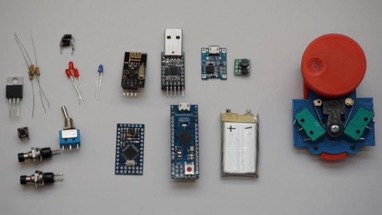
These are all of the parts required for both transmitter and receiver. Since this build also contains rotary encoder I've covered in an instructable you'll need parts for that as well. You can also find here STL file with knob for the encoder which is a bit shorter than the original and looks better in the remote.
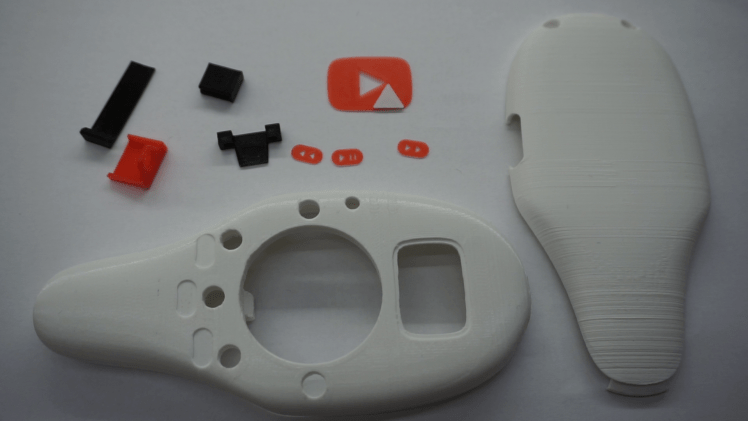
Step 3: 3D Printing
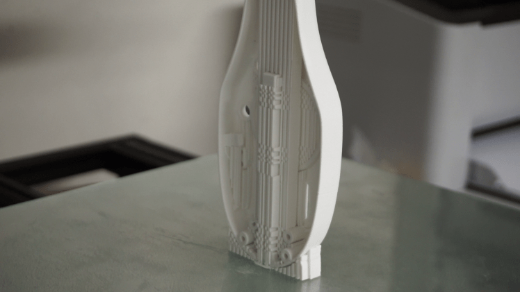
As I mentioned this build requires rotary encoder I've built in my last instructable (here) However I adjusted the size of the knob slightly and the new STL file can be found here. The original file would work too. All of the files are in a correct orientation. The case requires support material and I'd suggest printing it at higher resolution and at slower speed especially at the end of the print the slower speed will result in a smoother finish. Remaining files don't require any special settings.
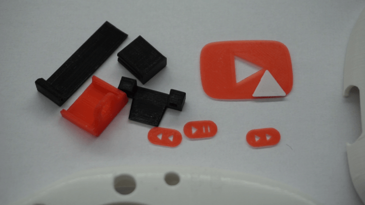
The case might be a bit rough where it was held by the support material. If you want better finish I'd suggest sanding these sections with 120 sandpaper. Now it's also a good time to tap the 4 holes on the case with M3 tap. All of the decorative pieces can be glued in place as well. The pushbuttons should fit snugly in place too. You might have to twist them in place with pliers. The small mode button can be placed on its stand as well but don't forget to insert its button cap as well. Next the red and blue mode LEDs can be simply press fit to the case.
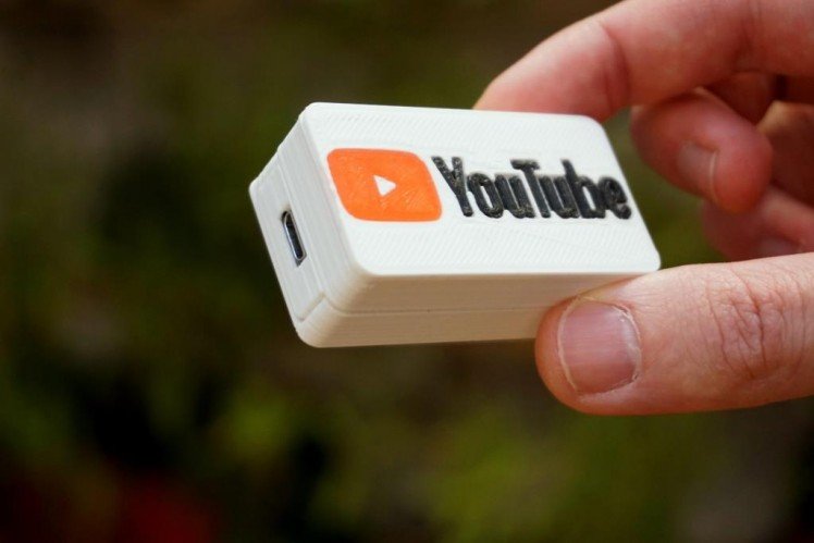
Step 4: Backlight of the Logo
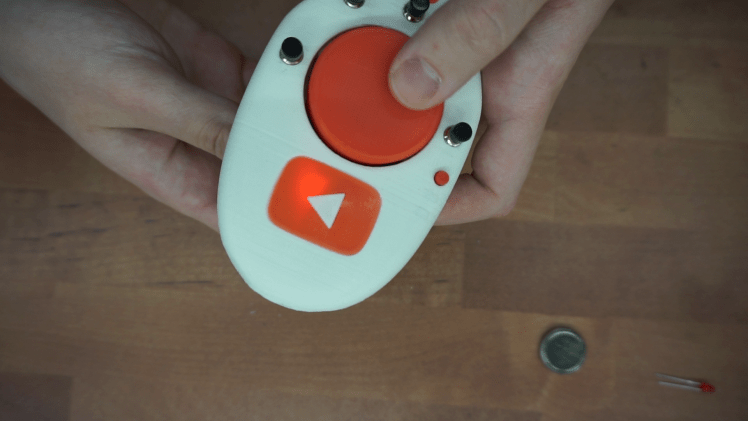
One of the signature features of the build is the back lit youtube logo on the front. It took me couple of hours to get this right and I've learned few things. Let me tell you how I'd do it if I had to build it again and then I'll also tell you what I actually built and why it's not the perfect solution. First of all I'd suggest simply placing two LEDs on each side of the logo and masking the surrounding. Whilst the light isn't going to be perfectly distributed it looks fine and it's quite bright.
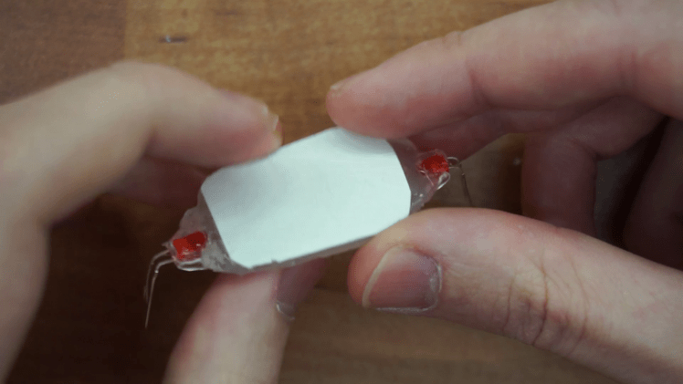
Since I wanted it to be perfect I have over complicated things. I've build this hot glue block which was roughly the shape of the logo. It was then cut precisely to the correct size, inserted in place and secured with more hot glue. The logo actually looks really nice but I did poor job of masking the insides of the case so the sides light up as well. That isn't however the biggest problem. There is just not enough clearance between this light spreader and rotary encoder which makes it jam sometimes. That is something I found out just once it was all assembled.
tl;dr Don't make the backlight complicated.
Step 5: Assembly

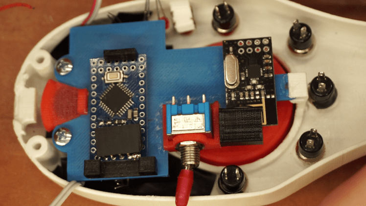
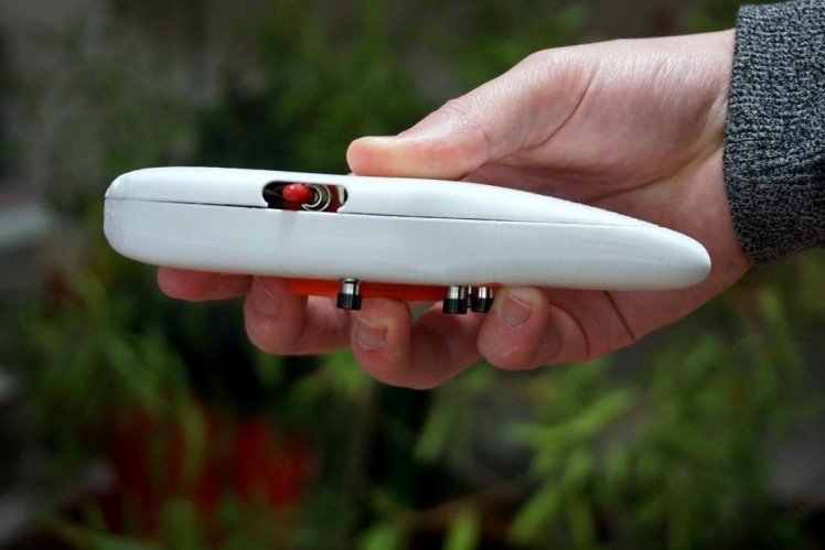
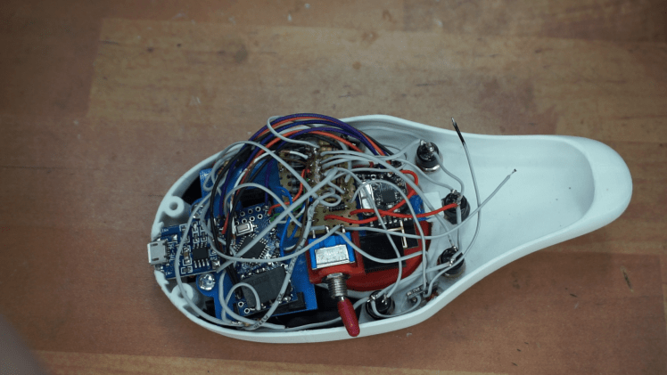
Apart from battery and voltage booster all of the electronics are placed on the bottom side of the rotary encoder. The power switch, RF module, charging board and arduino all have their 3D printed holders which are supposed to be glued on the rotary encoder. Start with the power switch which can mounted to the holder with it's nut and then needs to be placed in the corner of the encoder as shown in the picture. The holder has little notch that should lock it in place. I suggest using superglue and sanding both surfaces that will be touching. The same can be done with the holder for the RF module. This one doesn't need to be mounted precisely in place just roughly where it's shown in the picture. The holder for the charging board also has notch on one side that snaps right in place where it can be glued. And lastly the holder for arduino is two separate pieces. When glued the arduino should be just pushed in so check what should be the distance between them as arduinos can vary depending on where you got it from. Double check the distance as it will be difficult to change once glued in.
Step 6: Wiring
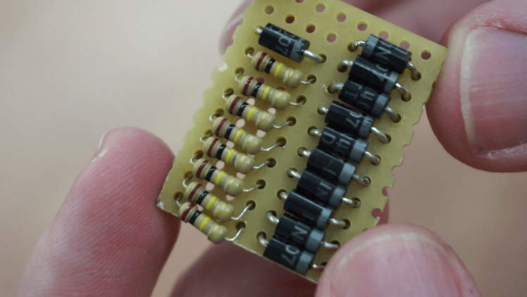
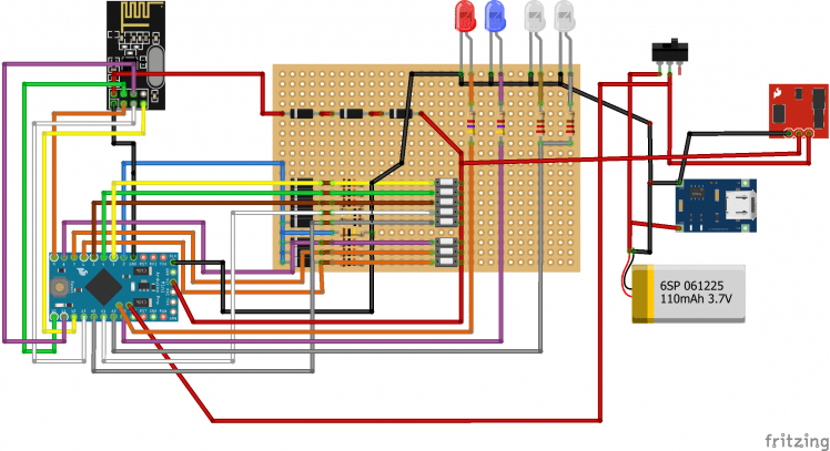
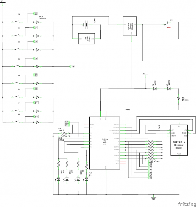
So far we have place for all of the boards but there are still a lot of passive components. It's time to put them all on a single board. Small rectangular pref-board will do the job. The schematic is available but it's really just bunch of resistors and diodes in series. The resistors for LEDs shouldn't be on this board as it's more convenient to solder them on the legs on the LEDs themselves. Don't bother gluing this board on the encoder as you'll need to access the bottom side and once you solder everything it'll held firmly just by the wires.
Now it's time to wire everything up. Don't bother with the battery yet. Everything else however needs to wired as shown on the provided schematic. Start by removing LEDs from the arduino pro mini as they might be drawing some current. Attach female pin header to programming pins of the arduino. I'd suggest doing that even if you have programmed it beforehand. First I connected the arduino and the RF module. Try not to put all of the wires in one spot as it might become too bulky. Next I soldered the arduino to the switches. Don't bother soldering wires on the bottom side of the pref board. Instead solder them directly on the legs of the resistor or diodes. Lastly connect the LEDs.
At this point it should be working. I would suggest powering it with bench lab power supply with current meter is series. This way you can check if it's not drawing too much current or if it's working. When on the remote should draw around 60mA and when in sleep it should be basically 0 so don't get fooled by that.
If you confirmed the remote works. You can install the battery. The battery I'm using is single cell 240mAh Li-po. At 41 x 26.5 x 6 mm it's the biggest battery that will fit in. It's held in place with double sided tape. The 5V booster can just be hot glued on the side just make sure you soldered the wires in first. It can then be connected as shown on the schematic.
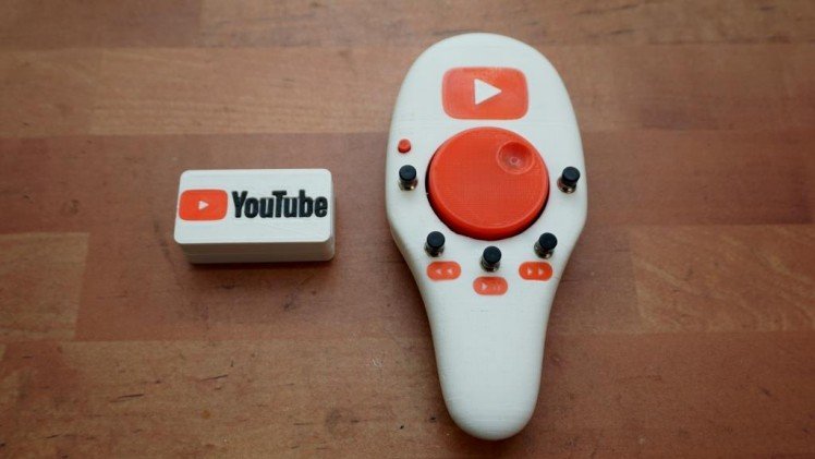
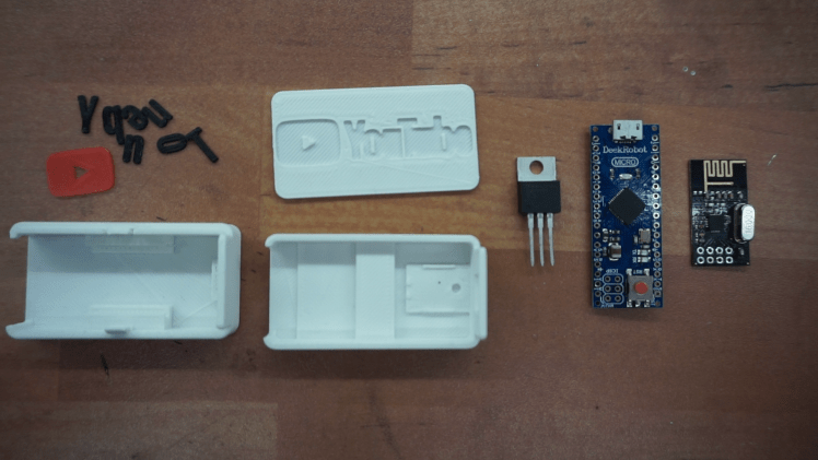
Step 7: Receiver
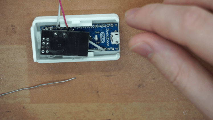
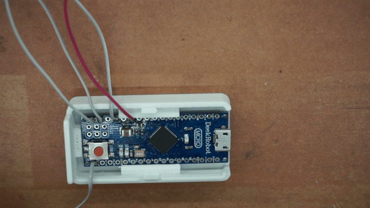
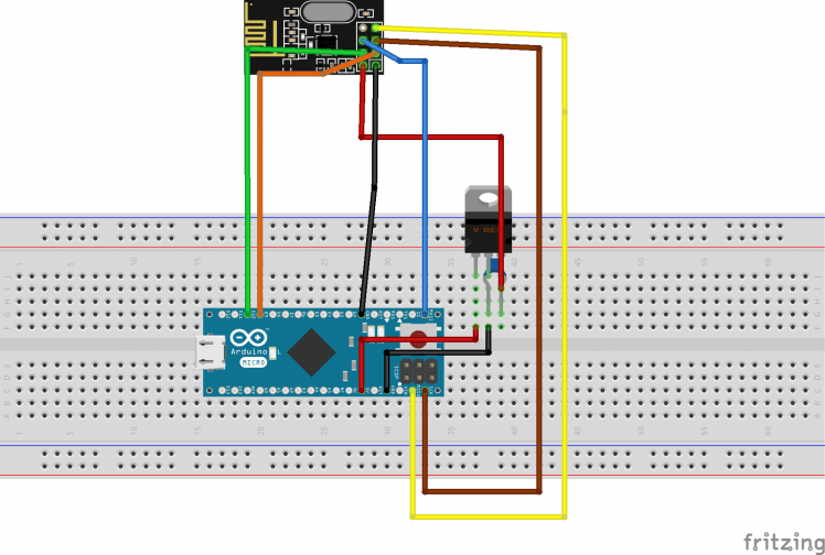
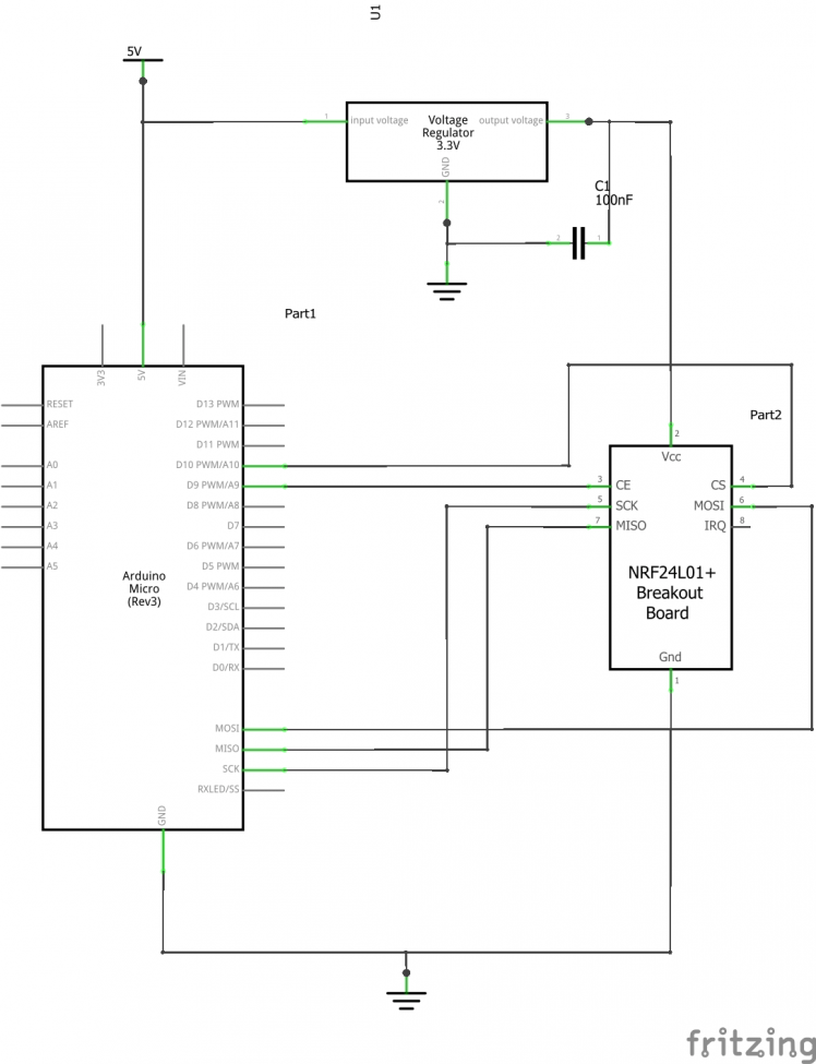
The receiver is fortunately a lot simpler than the transmitter. For this one we'll need just an Arduino micro and the RF module (NRF24L01). As mentioned previously the RF module requires 3.3V and the arduino does indeed have 3V3 pin however I measured around 4.8V on mine. So I had to add my own voltage regulator. Chances are the voltage regulator on your arduino will work. If it does the schematic is pretty much the same as I've provided but you simply connect the Vcc pin from the RF module to the 3V3 pin on arduino and ignore the regulator altogether.
Both the arduino and RF module are designed to slide it the 3D printed case. Keep the wires short because there isn't much room inside of the case. Test the arduino, with the code uploaded it should act as HID. If it works you can simply close the two halves of the of the case and they should just snap in place.
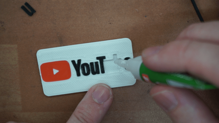
If you want to make it look a bit nicer you can also add the youtube logo. It's just glued on top of the receiver. The files need to be printed separately and apart from the red and white filament you'll also need a black one.
Step 8: Code
I've used arduino 1.8.5 for this project. All necessary libraries can be found in the library manager so you don't even have to worry about importing them yourself. When compiling the code make sure you have the correct board selected otherwise it might not compile. I've also run into some problems with uploading code to my arduino pro mini. This was most likely due to the USB to Serial adapter I was using. I found out that older arduino 1.0.5 would actually upload without any problem however it wouldn't compile my code for some reason. I ended up compiling the code on the 1.8.5 IDE and then uploaded the hex file with 1.0.5 . In case you have the same problem I found forum thread explaining exactly how this can be done. Link
If you want remap the keys and create new combinations you can do that by simply reprogramming the receiver. That way you don't have to take the receiver apart every time. Both codes are commented so if you are familiar with the arduino you should have no problem adjusting it. If you do however feel free to leave a comment.
Step 9: Done

Congratulations! you've built an amazing remote for your PC or Mac or android device. I'm pretty sure it works on anything as it's just a keyboard. Please let me know if you have any issues or if you found simpler solution. Also make sure to check out the video as it goes over the build process too.
Schematics, diagrams and documents
Code
Credits
Related products


Leave your feedback...