
Sending Data With Nrf24l01 Using Arduino

Made by Ron / Communication / Displays / Home Automation / Robotics
About the project
Send data from one Arduino to another using the NRF24L01 module. In this project we are gong to send Random Integer number from 100 to 1000
Project info
Difficulty: Easy
Estimated time: 1 hour
License: GNU General Public License, version 3 or later (GPL3+)
Items used in this project
Hardware components

Story
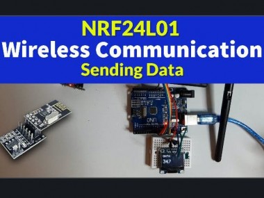
In this tutorial we will explore Wireless Communication and learn how to send data from one Arduino to another Arduino using the NRF24L01 module. For this project we are gong to send Random Integer number from 100 to 1000 every second.
Watch the video!
Step 1: What You Will Need
1 / 5
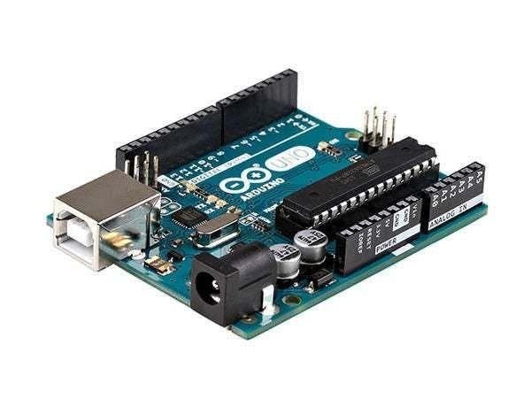
- 2X Arduino UNO (or any other Arduino)
- OLED I2C Display
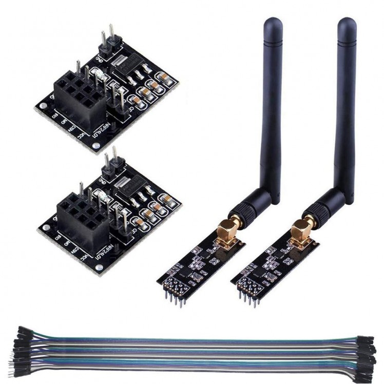
- 2x nrf24l01 module
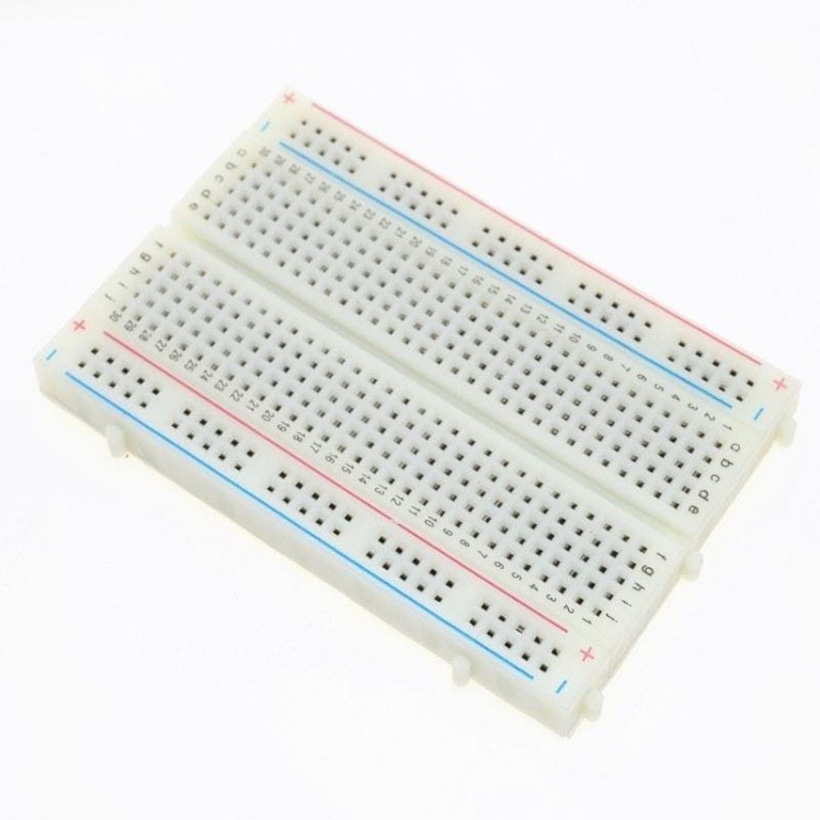
- Breadboard
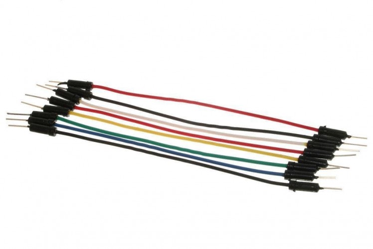
- Jumper wires
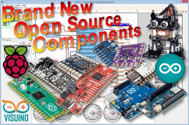
- Visuino program: Download Visuino
1 / 3

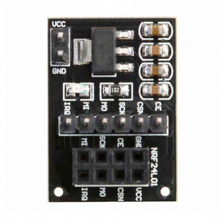
For this project we are using a NRF24L01 module together with a voltage adapter.
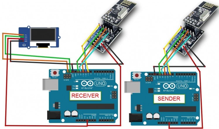
Wiring the Sender Arduino:
- Connect NRF24L01 Adapter pin [VCC] to Arduino pin [5V]
- Connect NRF24L01 Adapter pin [GND] to Arduino pin [GND]
- Connect NRF24L01 Adapter pin "Chip Enable" [CE] to Arduino Digital pin [9]
- Connect NRF24L01 Adapter pin "Chip Select" [CSN] to Arduino Digital pin [10]
- Connect NRF24L01 Adapter pin [SCK] to Arduino Digital pin [13]
- Connect NRF24L01 Adapter pin [MO] to Arduino Digital pin [11]
- Connect NRF24L01 Adapter pin [MI] to Arduino Digital pin [12]
Wiring the Receiver Arduino:
- Connect NRF24L01 Adapter pin [VCC] to Arduino pin [5V]
- Connect NRF24L01 Adapter pin [GND] to Arduino pin [GND]
- Connect NRF24L01 Adapter pin "Chip Enable" [CE] to Arduino Digital pin [9]
- Connect NRF24L01 Adapter pin "Chip Select" [CSN] to Arduino Digital pin [10]
- Connect NRF24L01 Adapter pin [SCK] to Arduino Digital pin [13]
- Connect NRF24L01 Adapter pin [MO] to Arduino Digital pin [11]
- Connect NRF24L01 Adapter pin [MI] to Arduino Digital pin [12]
- Connect OLED Display pin [SCL] to Arduino pin [SCL]
- Connect OLED Display pin [SDA] to Arduino pin [SDA]
- Connect OLED Display pin [VCC] to Arduino pin [5v]
- Connect OLED Display pin [GND] to Arduino pin [GND]
1 / 2
The Visuino: https://www.visuino.eu also needs to be installed. Download Free version or register for a Free Trial.
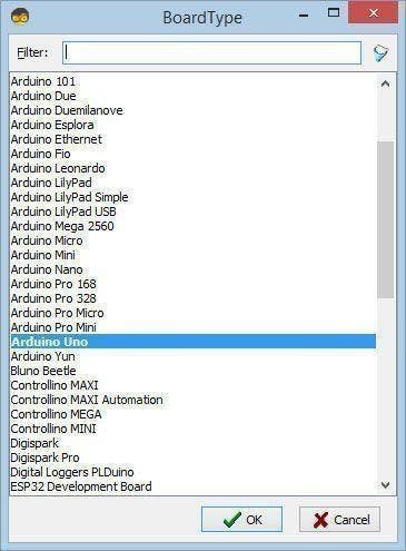
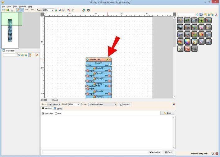
Start Visuino as shown in the first picture Click on the "Tools" button on the Arduino component (Picture 1) in Visuino When the dialog appears, select "Arduino UNO" as shown on Picture 2
Step 4: For Sender Arduino - in Visuino Add, Set & Connect Components
1 / 8
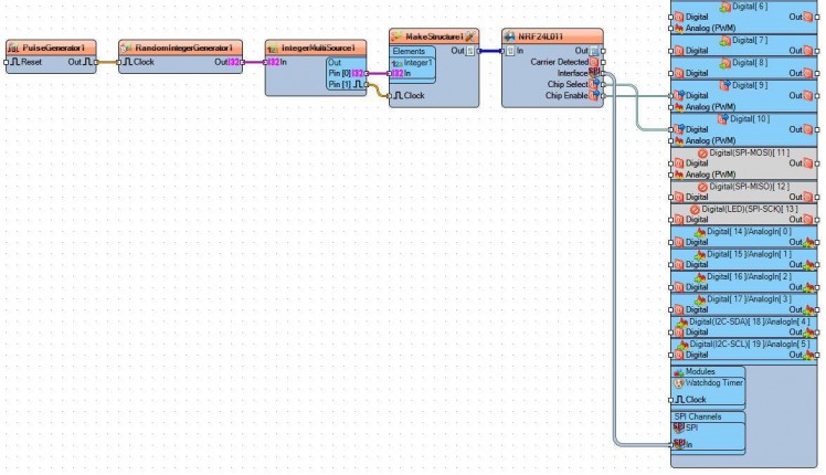
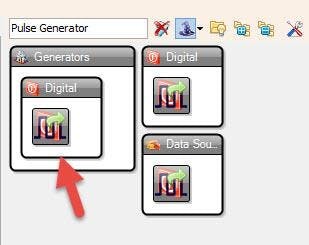
- Add "Pulse Generator" component
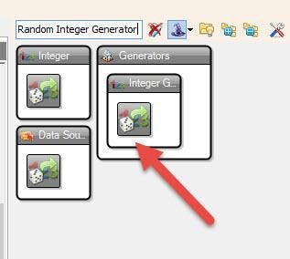
- Add "Random Integer Generator" generator
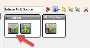
- Add "Integer Multi Source" generator
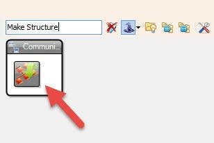
- Add "Make Structure" generator
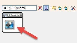
- Add "NRF24L01 Wireless" component
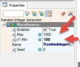
- Select "RandomIntegerGenerator1" and in the properties window set Min to 100 and Max to 1000 (Picture 6), This means that we will send random numbers betwen 100-1000
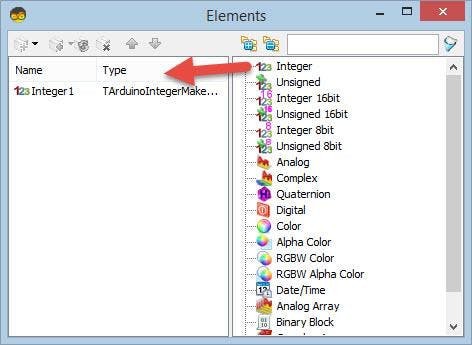
- Double click on the "MakeStructure1" and in the "Elements" window drag "Integer" to the left side and close the "Elements" window
- Connect "PulseGenerator1" pin [Out] to "RandomIntegerGenerator1" pin [Clock]
- Connect "RandomIntegerGenerator1" pin[Out] to "IntegerMultiSource1" pin [In]
- Connect "IntegerMultiSource1" Out pin [0] to "MakeStructure1" > "Integer1" pin [In]
- Connect "IntegerMultiSource1" Out pin [1] to "MakeStructure1" pin [Clock]
- Connect "MakeStructure1" pin [Out] to "NRF24L011" pin [In]
- Connect "NRF24L011" pin Interface [SPI] To Arduino board pin [SPI]
- Connect "NRF24L011" pin [Chip Select] To Arduino board digital pin [10]
- Connect "NRF24L011" pin [Chip Enable] To Arduino board digital pin [9]
Upload the Project to the Arduino Board (see the Generate, Compile, and Upload the Arduino Code step)
Step 5: For Receiver Arduino - in Visuino Add, Set & Connect Components
1 / 7
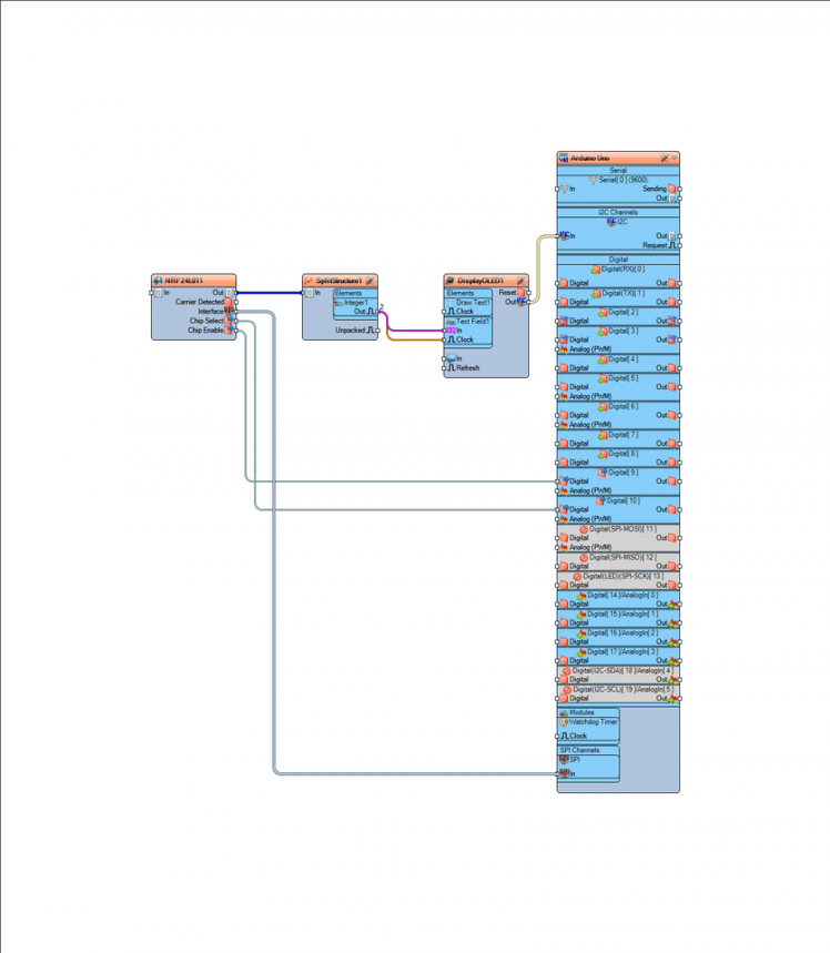
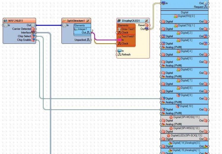
- Add "NRF24L01 Wireless" component
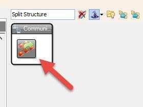
- Add "Split Structure" component
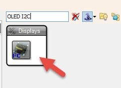
- Add "OLED I2C" component
- Double click on the "SplitStructure1" and in the "Elements" window drag "Integer" to the left sideClose the "Elements" window
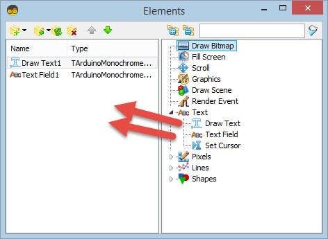
Double click on the "DisplayOLED1" and in the "Elements" window drag:
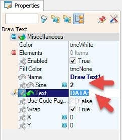
- "Draw Text" to the left side and in the Properties window set "Size" to 2 and "Text" to Data:
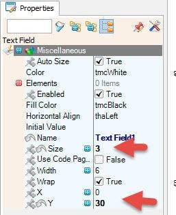
- "Text Field" to the left side and in the Properties window set "Size" to 3 and "Y" to 30
- Close the "Elements" window
Upload the Project to the Arduino Board (see the Generate, Compile, and Upload the Arduino Code step)
Step 6: Generate, Compile, and Upload the Arduino Code
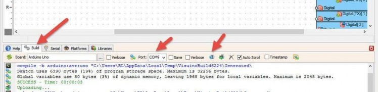
In Visuino, at the bottom click on the "Build" Tab, make sure the correct port is selected, then click on the "Compile/Build and Upload" button.
Step 7: PlayIf you power the Arduino modules, the OLED Display connected to the Receiver Arduino will start to show the Random Integer numbers from that are received from the sender Arduino.
Congratulations! You have completed your project with Visuino. Also attached are the Visuino project files for Sender and Receiver, that I created for this Tutorial, you can download it and open it in Visuino: https://www.visuino.eu
Step 8: Tips & Troubleshooting- If the you do not see any numbers displayed on the OLED display, please check the wires connected to the nrf24l01 modules, a lot of times a small bad connection can cause such problems.
- To increase the nrf24l01 module range you can lower the Data Rate to 250KBps (See Picture1)
- Optionally Isolate the module in a metal box
- Optionally add external power supply to the module (In this case make sure that the GND from Arduino and Power supply is connected together)
- There is a great video on youtube where 30km range was achieved using the nrf24l01 https://www.youtube.com/watch?v=4XRp7pkZgPM
Schematics, diagrams and documents
Code
Credits
Related products


Leave your feedback...