
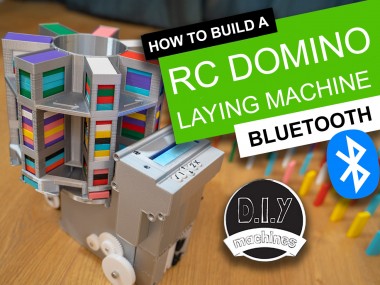
Rc Arduino Domino Layer With Bluetooth App Control

Made by DIY-Machines / 3D Printing / Games & Gaming / Retro Tech / Robotics / Vehicles
About the project
How to 3D print and assemble your very own programmable and remote controllable automatic domino laying machine.Who likes knocking down absurdly long runs of dominoes? I do! Who doesn't like laying them all by hand. I don't. That's why I made this....
Project info
Items used in this project
Story
How to 3D print and assemble your very own programmable and remote controllable automatic domino laying machine.
Who likes knocking down absurdly long runs of dominoes? I do. Who doesn't like laying them all by hand. I don't. That's why I made this. ?
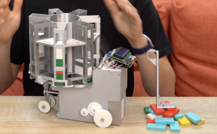
Using some basic electronics this machine can line up well spaced rows of wooden dominoes. You can drive it around corners, forwards and backwards - just don't drive into your already laid dominoes. You can enter a list of instructions to your robot via the Arduino IDE, upload with USB and then send it on it's way to follow your instructions, or you can open the Blynk phone app and drive it live via bluetooth.
Step 1: Video Instructions
If you would like see the machine in action or prefer to follow a video guide then I have made two videos to go with these instructions. The first one covers the majority of the 3D printing, assembly, electronics, and programming from the Arduino IDE.
The second video show how to upgrade the machine with the addition of bluetooth so that we can drive it around like an RC car (laying dominoes at the same time of course) using a free app built in Blynk.
Step 2: Bill of Materials and Other Resources
You're going to need some supplies to build one of your own. Here is a list of those items with links to them on Amazon:
- Elegoo Arduino Uno (x1) - https://geni.us/ArduinoUno
- Micro continuous rotation servo (x1) - https://geni.us/360MicroServo
- Micro 180º servo (x1) - https://geni.us/MicroServo
- LM317 DC-DC Converter (x1) - https://geni.us/LM317
- Six AA Battery Holder (x1) - https://geni.us/6AABatteryHolder
- AA Batteries (x6) - https://geni.us/AABatteries
- 1:90 TT DC Motor (x1) - https://geni.us/1-90GearedTTMotor
- L298N Motor Driver (x1) - https://geni.us/L298N
- Limit Switch with roller arm (x2) - https://geni.us/ContactSwitch
- 1602 LCD Shield with keypad (x1) - https://geni.us/1602LCDKeypad
- HM10 Bluetooth Module (x1) - https://geni.us/HM10Bluetooth
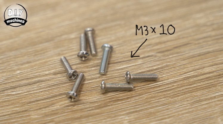
- M3 and M5 Bolts - https://geni.us/NutsAndBolts M3x6 (x2) M3x10 (x21) M5x15 (x2) M5x20 (x2) M5x25 (x1)
- Rubber Bands - https://geni.us/RubberBands
- Dominoes I used (x lots) - https://geni.us/Dominoes
- 4 Way Wire Connector (x1) - https://geni.us/WagoConnectors
- Electrical ‘Hookup’ wire - https://geni.us/22AWGWire
- Velcro Cable Tidy (for domino ejector) - https://geni.us/VelcroCableTidy
- Filament for 3D printing:
- Silky silver from Geeetech: https://geni.us/GeeetechSilkSilverPLA - White PLA: https://geni.us/GeeetechSilkSilverPLA
You can find all the files for 3D printing in one place on Thingiverse: https://www.thingiverse.com/thing:4694940
Step 3: 1st Half of the Body and Servo
We need to start with the first half of the body which is a 3D printed part. I have printed all my parts for this project in PLA plastic - PETG would also be fine.
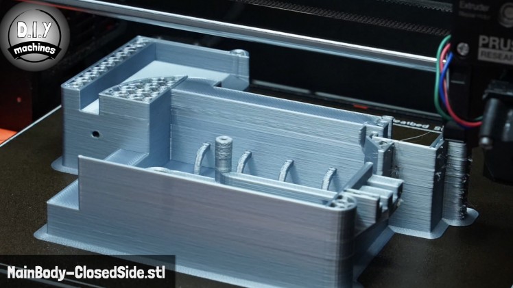
The first part is called 'MainBody-ClosedSide.stl. I printed mine at a layer height of 0.3mm (as I had a larger 0.6mm nozzle fitted to my printer at the time of printing this) and added a brim to ensure adhesion. There is no needs for support on this part - I've worked hard to avoid them where possible in the design.
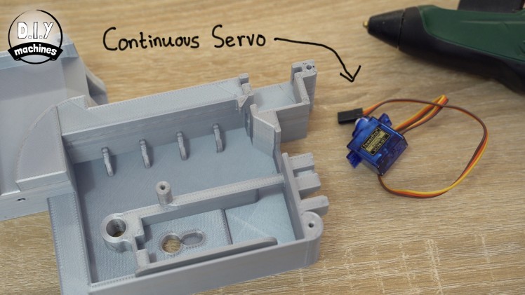
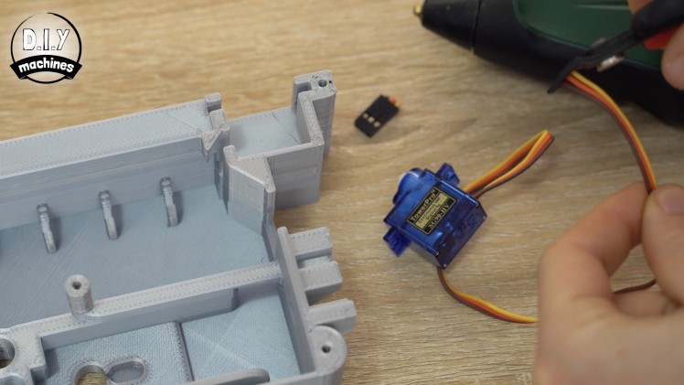
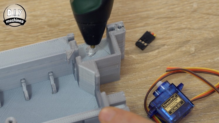
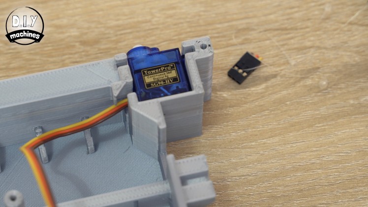
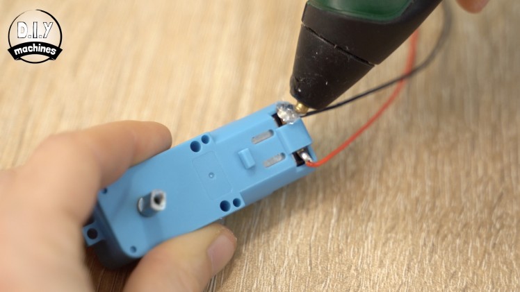
Once printed we can take the continuous rotation servo and cut off the end of the connector. Use some hot melt glue to then secure it in its recess towards the top right of the print. The wires should exit to the left through the little passage way.
Step 4: The 1st Contact Switch

For this step will you need:
- Contact switch x1
- Some wires
- Hot melt glue

Prepare two 18cm long lengths of wire. Solder one each to the common and normally open legs on the contact switch. On mine these are marked as C and NO.
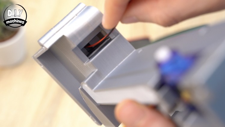
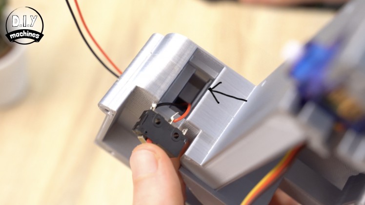
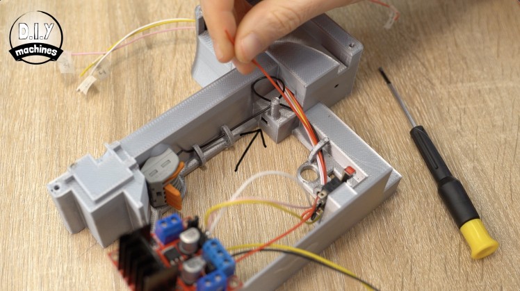
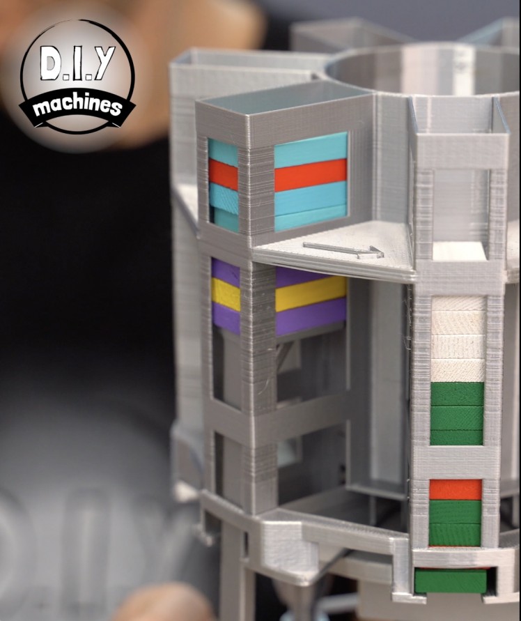
The wires can then be threaded though the tunnel in the 3D printed part. You can then use some hot melt glue to attach the contact switch in position. Its back edge should push up against the ridge shown by the arrow I added in the photos.
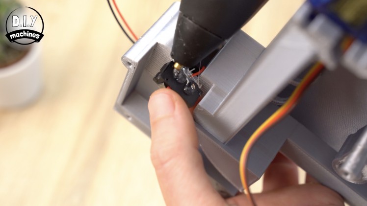
Use hot melt or some other reworkable glue as you may need to adjust its position later. Also be sure to keep the glue from interfering with the switch mechanism itself.
Step 5: Installing DC Geared Motor
For this step will you need:
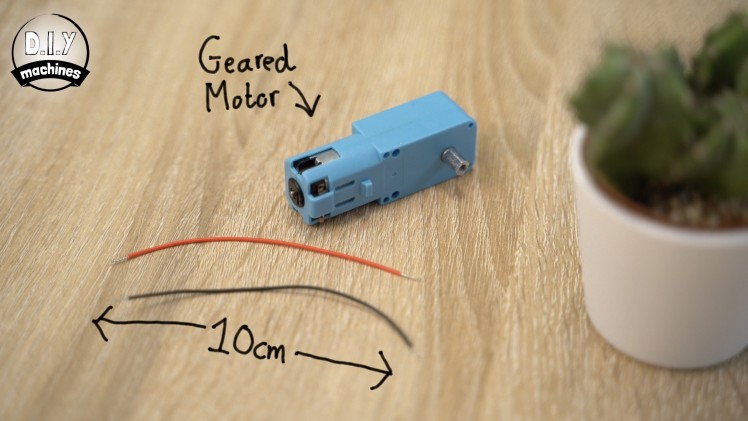
- DC Geared Motor (at lest 1:90 gearing)
- Wires
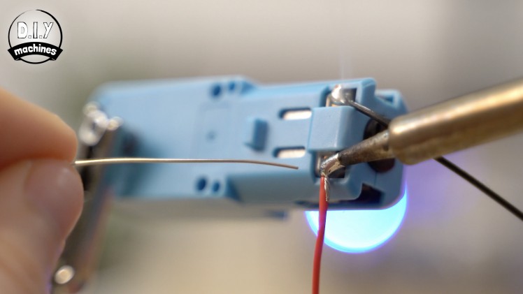
Cut, strip, and tin a pair of 10cm lengths of wire which can then be soldered to the two terminals on the DC motor.
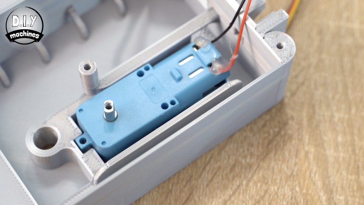
Ensure the wires are exiting away towards the back of the motor and apply some hot melt glue to act as strain relief to both the wires and the small little tabs which they have just been soldered to.
Use some more glue to fit the DC motor into the housing whilst ensuring that the shaft of the motor is central in its hole when seen from the other side of the housing.
Step 6: Add DC Motor Gears & Axle
For this step will you need:
- Printed parts:
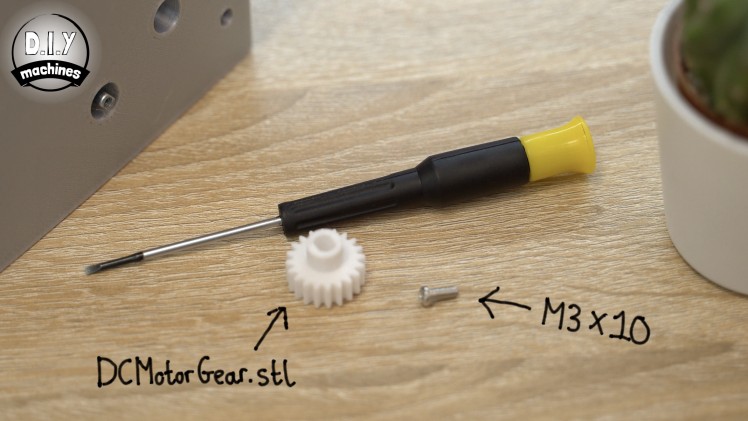
- DCMotorGear.stl
- DoubleCog.stl
- DriveAxle.stl
- PoweredWheel.stl
- M3 x 10mm bolt (x2)
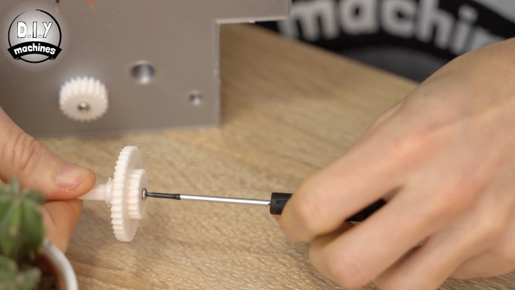
- M5 x 25mm bolt (x1)
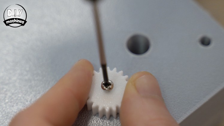
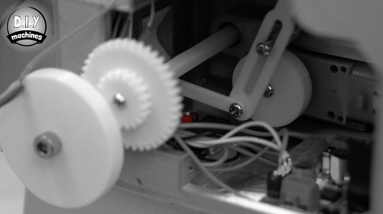
The next 3D printed part required is the 'DCMotorGear.stl. Again, no support are needed for this part. Use the first M3 x 10mm bolt to fit this to the shaft of the DC motor from the outside.
If your shaft doesn't have a threaded insert then it can also be fitted with glue.
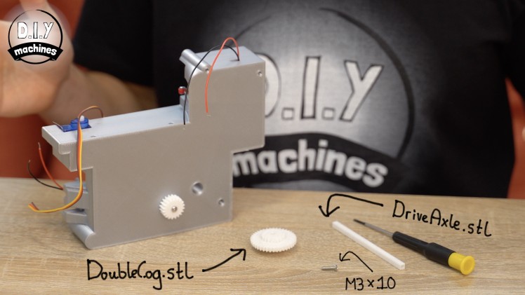
Now the 'DoubleCog.stl' and 'DriveAxle.stl' parts can be printed and joined together with the other M3x10 bolt. This sub assembly is then passed through the adjacent hole in the printed body so that the large teeth of the gear mesh with the already installed gear.
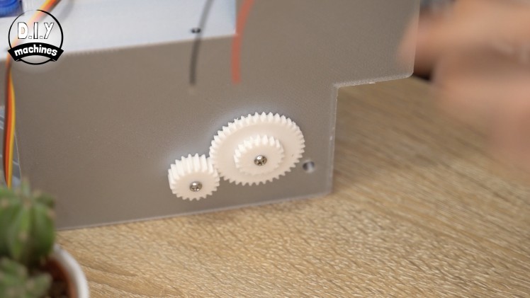
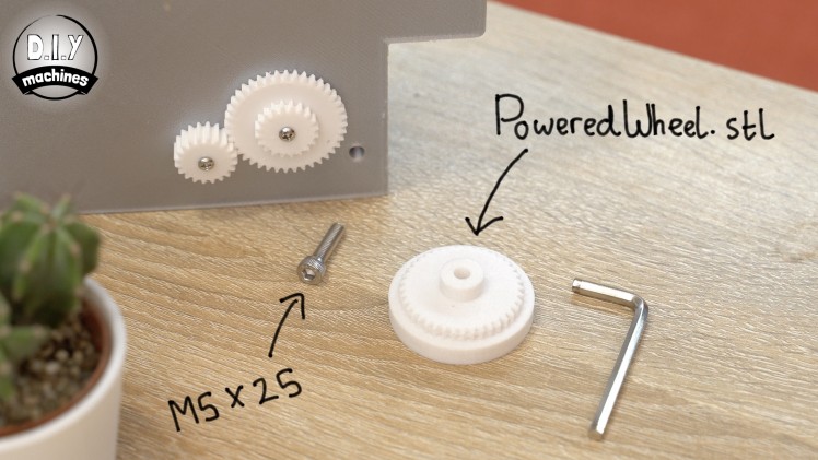

To complete this set of cogs pass the M5x25mm bolt through the printed 'PoweredWheel.stl' and then attach this to the main body so that the smallest of the cylinders on the print is against the main body and the largest smooth cylinder of the print is on the outside. Once the bolt has been tightened, loosen it off slightly so that the wheel can rotate freely but does not wobble too much.
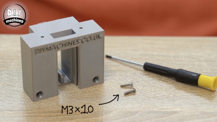
Step 7: Attach Back of the Main Body
For this step will you need:
- Printed parts:
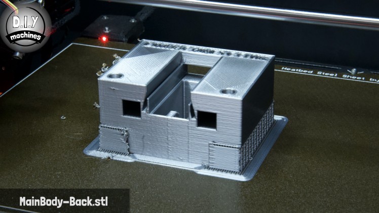
- MainBody-Back.stl
- M3 x 10mm bolt (x2)
I recommend printing this part on its back so that the writing is facing upwards. this help to ensure that the the thin fins are printed well and that no bridging occurs where we need dominoes to be able to easily slide past.
After you have printed the MainBody-Back.stl and removed the supports we can attach it to the main body with the two M3x10mm bolts.
One through the access hole in the front and the other from below. (Through the square opening).
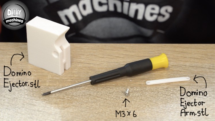
Step 8: Prepare Domino Ejector
For this step will you need:
- Printed parts:
- DominoEjector.stl
- DominoEjectorArm.stl
- M3 x 6mm bolt (x1)
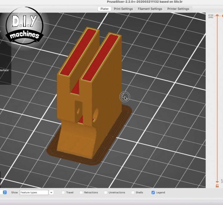
Print the 'DominoEjector.stl' and 'DominoEjectorArm.stl'. When printing the DominoEjector part it is important to print it upside down. This results in the layer lines running in the same direction that it will slide back and fourth through the machine - reducing friction and noise. Why upside down? This also is how this part has been designed so that we can print it without supports which will also help to ensure a smooth motion.
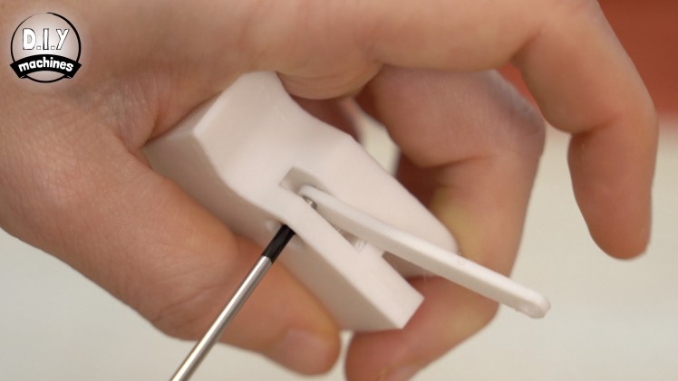
The arm is inserted into the cutout and secured with the M3 x 6mm bolt through the side of the printed part.
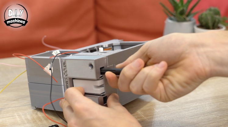
This assembly can then be slid into place by inserting the end with the arm protruding through the back of the domino machine first followed by the larger ejector itself.
Step 9: Connect Arms to the DC Motor

For this step will you need:
- Printed parts:
- DCMotorCrank.stl
- DominoCollectorArm.stl
- M3 x 10mm bolt (x3)
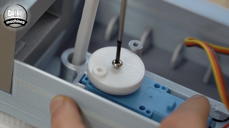
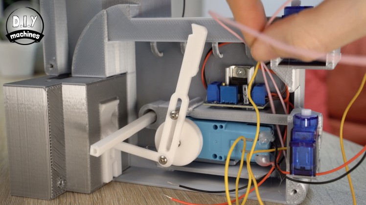
The 3D printable 'DCMotorCrank.stl' is fitted over the shaft of our DC motor on the inside of the main housing. Again, if your shaft is threaded like mine you can use a bolt to secure the printed part. If their is no thread on your shaft you can use glue instead.
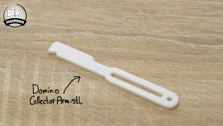
The DominoCollectorArm.stl component is then installed, first by passing an M3 x 10 bolt though the long slot in the arm. Ensure that the hooked end of the arm is facing towards the back of the machine (away from the servo) when you install it - check the photos if you are not sure what I mean.
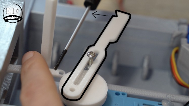
This should not be tightened so much as to restrict the movement of the arm. It should allow the arm to slide up and down freely.
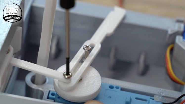
The final M3x10 bolt is used to connect the two arms to the crank. This needs to be done with the domino collector arm (the large one with a slot in it) first so that it touches the crank, followed by the thinner domino ejector arm on top of this.
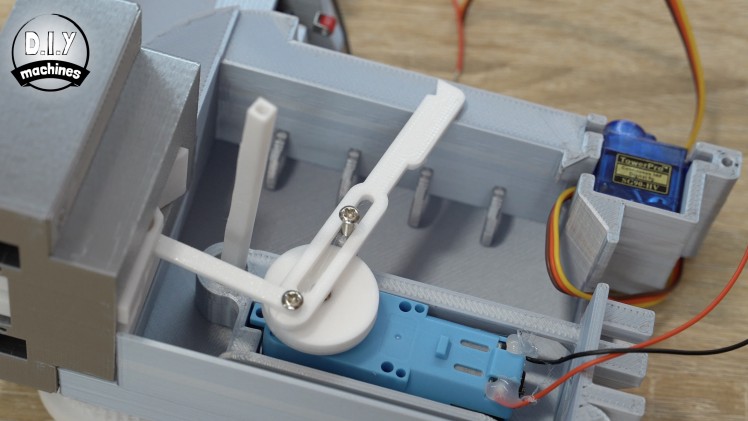 This bolt also should be left slightly loose so that both arms can freely rotate around the shaft of the bolt without too much wobble.
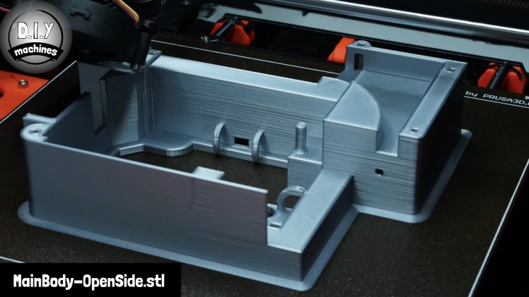
Step 10: Starting 'the Other Half'
For this step will you need:
- Printed parts:
- 'MainBody-OpenSide.stl'
- Wire connector
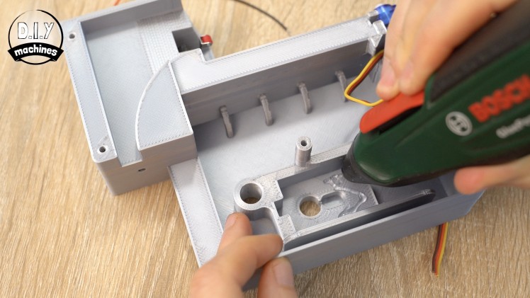
'MainBody-OpenSide.stl' is the next part that can be 3D printed. This piece does not require any supports and mine was printed in PLA like the rest of the project.
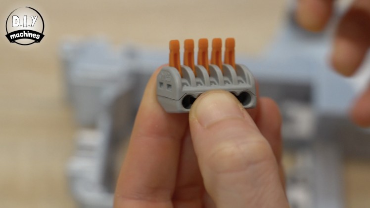
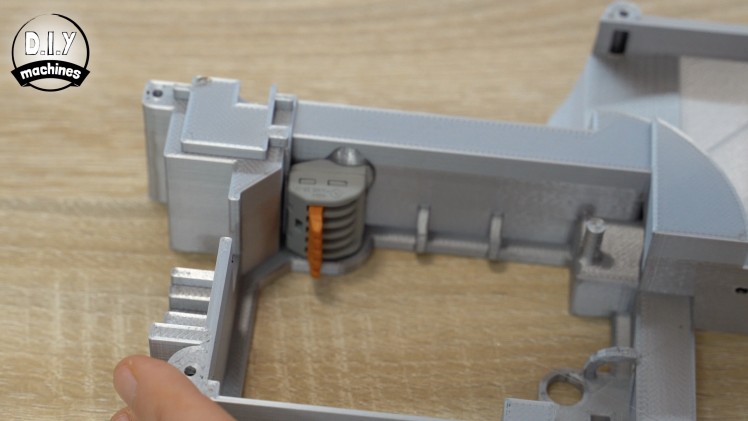
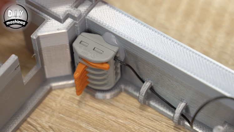
If you are using a Wago connector as I am, now is a good time to open the little sprung arms for easier connection of the wires later. Use some glue to fix it to the underside of the printed housing .

Attachments
Step 11: The Second Contact Switch
For this step will you need:
- Contact switch
- Wires
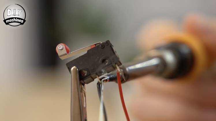
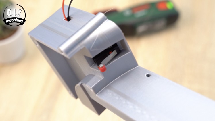
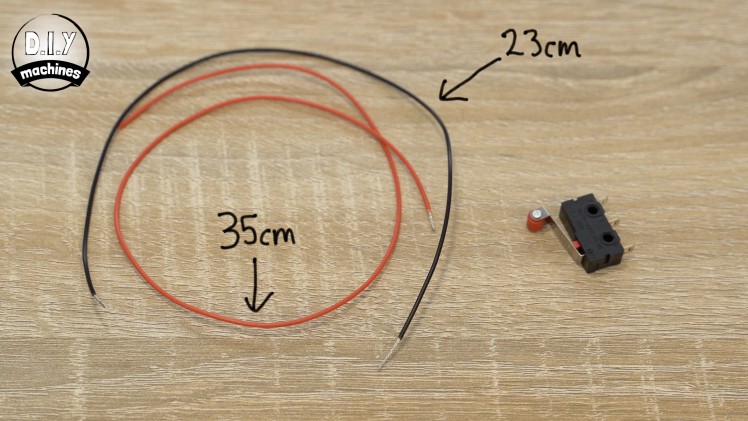
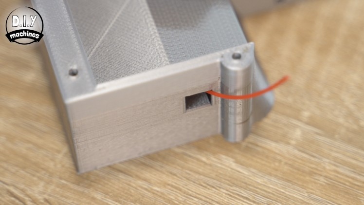
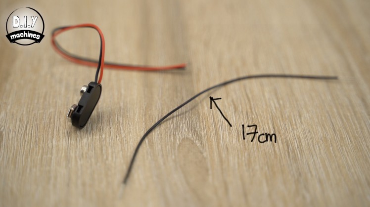
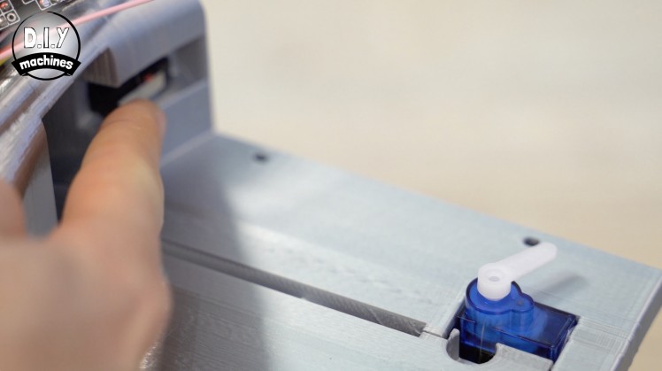
Measure, strip, and tin a couple of wires. One should be 23cm long and the other 35cm long. These can then be soldered to the same common and normally open legs like we did with our first switch. It does not matter which length wire is connected to which leg.

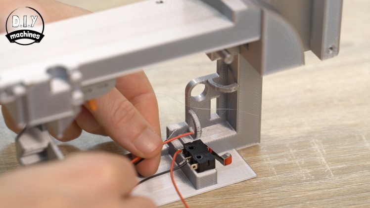
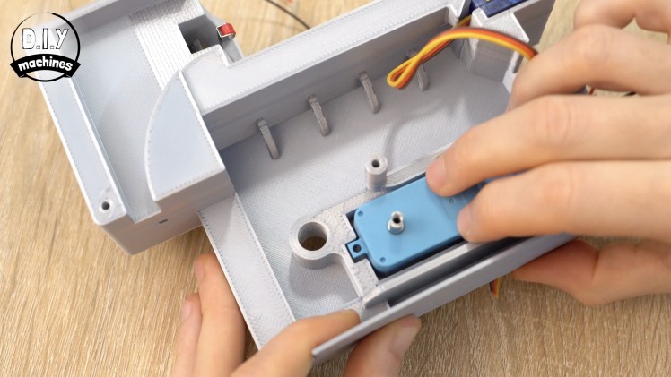
Use some glue to fix it to its platform at the bottom of the print. Ensure that the orientation (the way its arm is sprung) matches the switch in the photos for this step and that the switch is positioned so that it right side is against the right stop and the back is against the back stop.
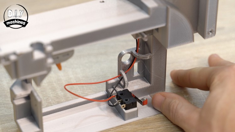
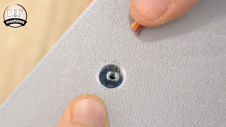
The hoops on this print are for threading our wires through. Thread both the wires for the contact switch through the first two hoops.
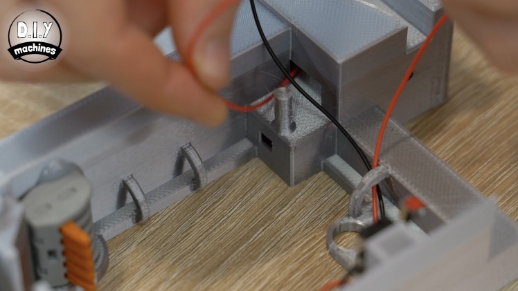
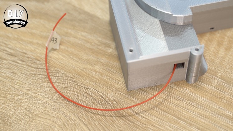
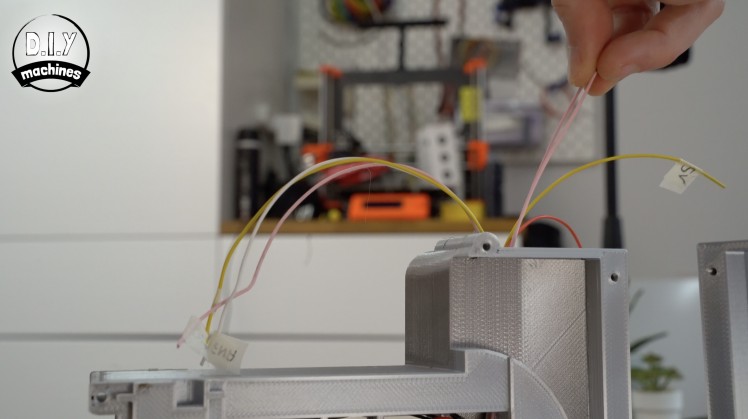
Thread the 35cm long wire though the runner just behind the printed column so that it comes out at the top of the print. Use some masking tape to label this wire as A3 as this is the pin we will be connecting it to on our Arduino later.
The 23cm wire is instead passed around the column and carries on through the row of hoops at the top before being inserted into our wire connector.
Step 12: DC Motor Driver (L298N)
For this step will you need:
- L298N
- Wires
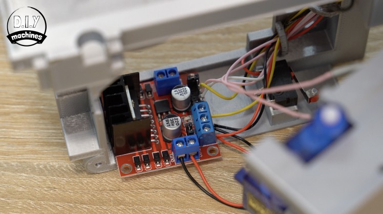
There may or may not be some jumpers fitted onto the pins on your motor driver. You need to ensure that there is one fitted over the two pins behind the terminal blocks (see the photo). This connects the 5v terminal to the boards linear regulator and will provide 5v to power our Arduino and LCD shield.
If there are any additional jumpers blocking your access to a pin they can be removed.
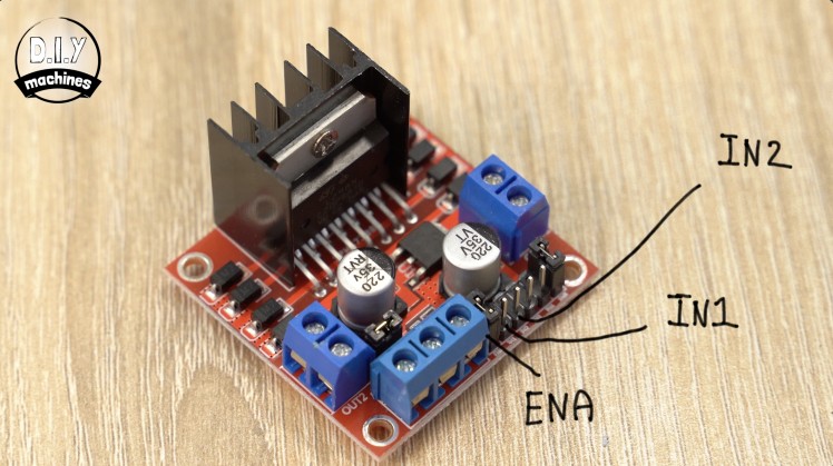
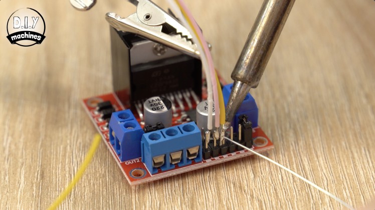
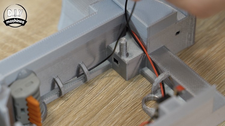
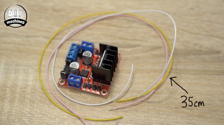
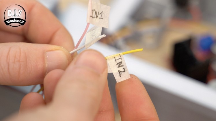
Prepare three lengths of 35cm long wire. These need to be connected to the pins marked as ENA, IN1 and IN2. I soldered mine.
All three of these wires should then be threaded through the first two hoops and then through the tunnel towards where our Arduino will be later. Label each of these wires.
Connect a 22cm length of wire to the both the VCC and ground terminals. A new 30cm length of wire (yellow in the images) is connected to the terminal marked as 5v.
Thread the 22cm VCC wire though the first two hoops and then into the as yet unused hole below the pin/column for connection to our battery later. The ground wire goes all the way around through all the hoops and is connected to our wire connector.
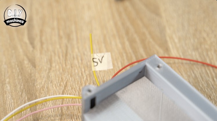
The 5V wire goes through the first two hoops and then through the tunnel to join where our other wires are waiting to be connected to the Arduino later. Don't forget to add a label to the wire.
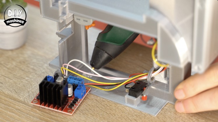
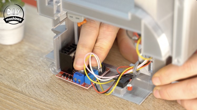
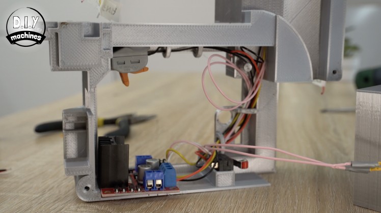
Finally we can use some glue to fit the motor driver board itself into place. There is a ledge at the back of the print which the board should be butted up to, as well as the ledge on the side of the print.
Gently pull on our labelled wires to pull through any slack inside the housing without putting to much strain on the wires.
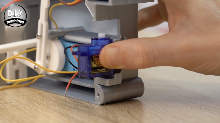
Step 13: Installing 180° Servo
For this step will you need:
- 180° servo
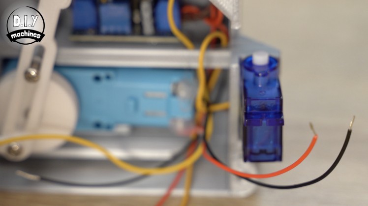
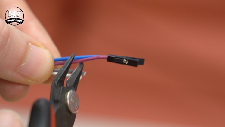
As we did with the first servo, trim the connector off the end of its wire. Peel the orange signal wire all the way back to separate it from the other two wires on both the servos (the one we just trimmed as well as the one already installed in the first half of the housing we worked on).
Trim the length of the brown and red power wires on both servos to around 9cm in length.
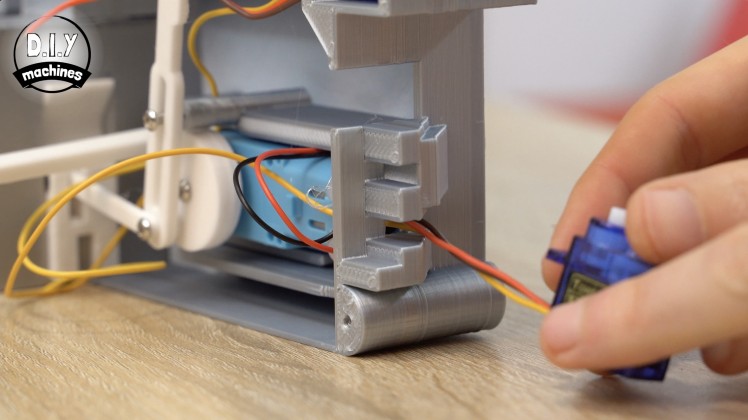
Pass all three wires for the 180°steering servo through the hole in the front of the main body and then use some glue to set the servo in place.
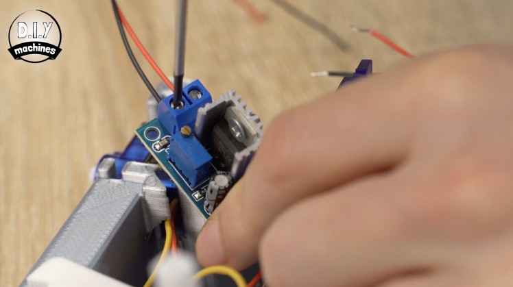
Step 14: Prepare LM317
For this step will you need:
- LM317
- Multimeter
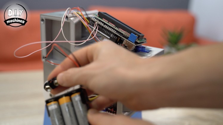
- 6 AA Batteries and case
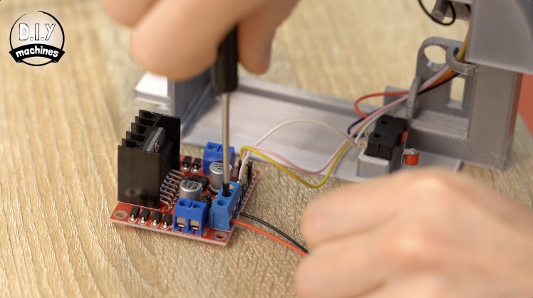
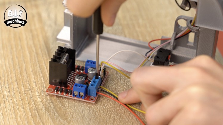
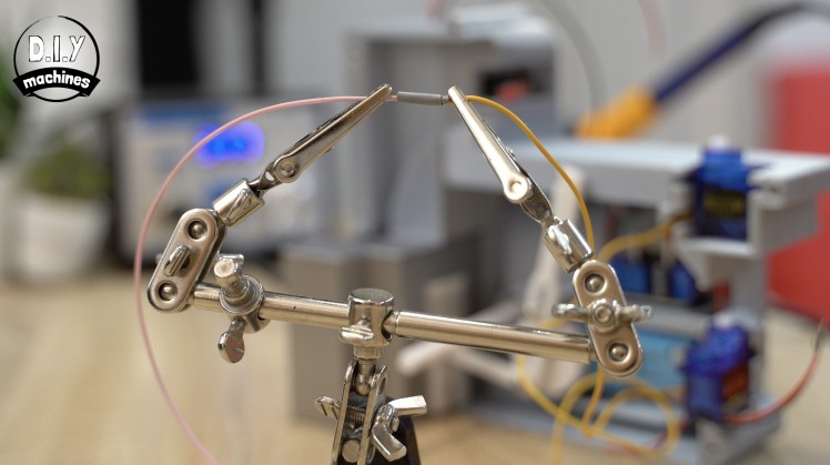
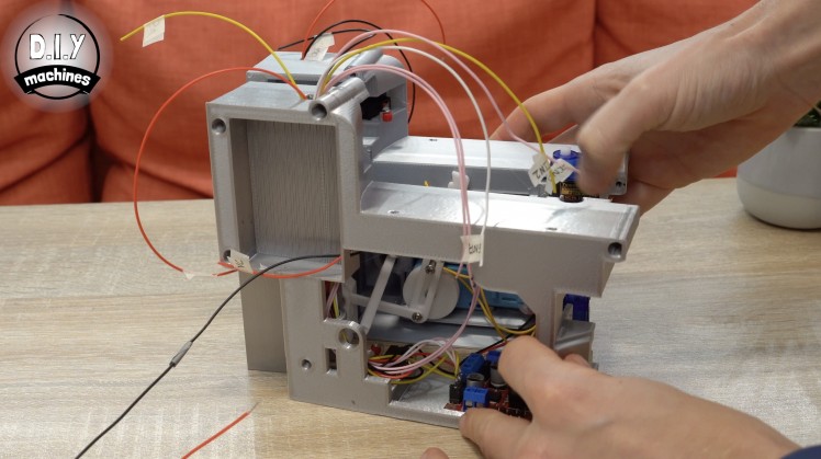
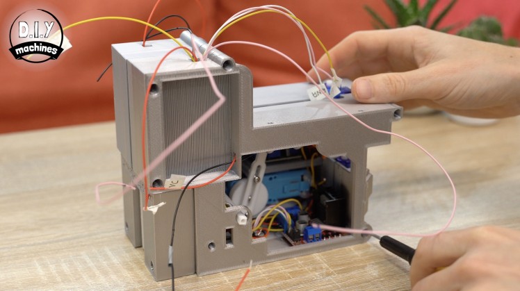
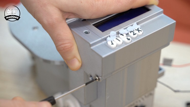
Before we can connect the LM317 we need to set its output voltage by adjusting the potentiometer on it whilst measuring its output voltage with a multimeter.
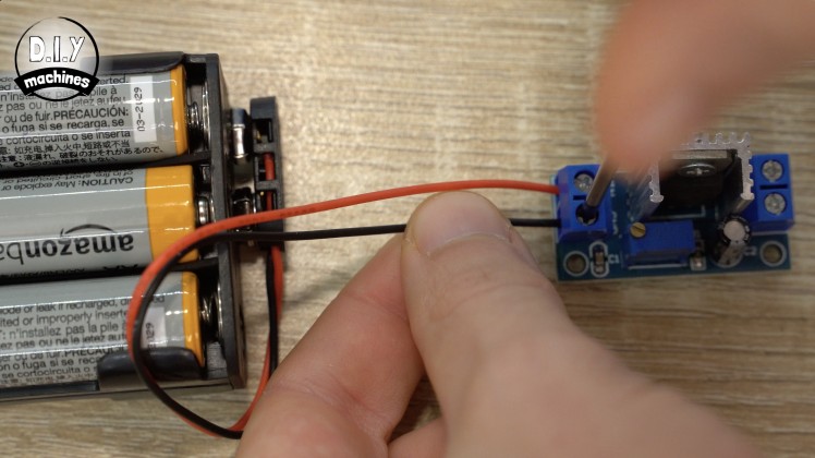
To do this, connect our batteries to the two input terminals and a multimeter to the two output terminals. Use a small screwdriver to turn the screw on top of the potentiometer until you get as close to a 6v reading on your multimeters screen as you can.
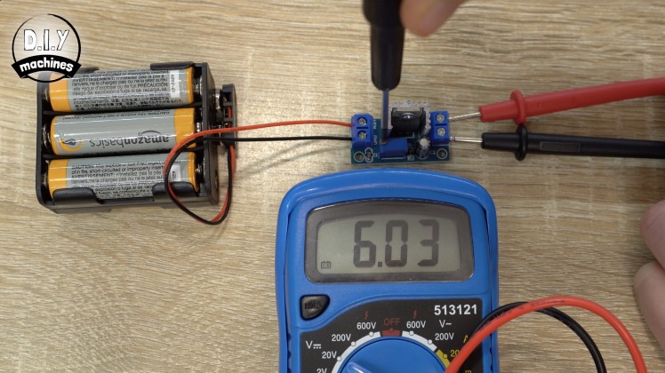
I settled for 6.03v. Once done you can disconnect both the batteries and multimeter from the LM317.
You can then wrap matching pairs of power wires from the two servos and solder them together as one ready to insert into the terminals on the regulator.

The pair of red wires are inserted into the positive out terminal on the board and the pair of brown wires are inserted into the negative output terminal. On the two input terminals of the board connect two new 21cm long wires.
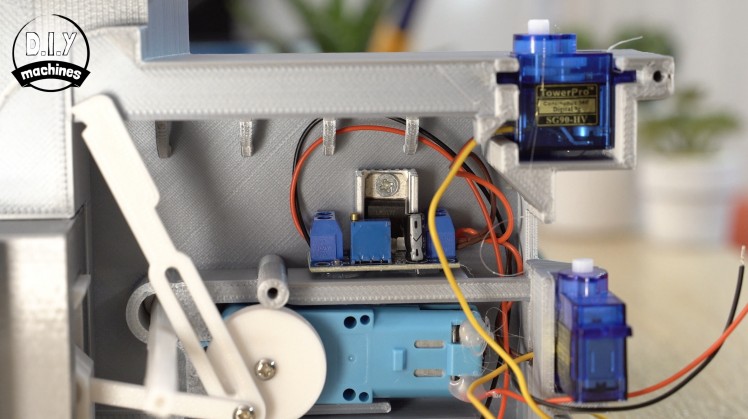
The module is then glued into place on the 3D printed ledge behind the domino collector arm. The input wires are kept tidy by being passed through the hops and then down beside the shelf the LM317 now resides on.
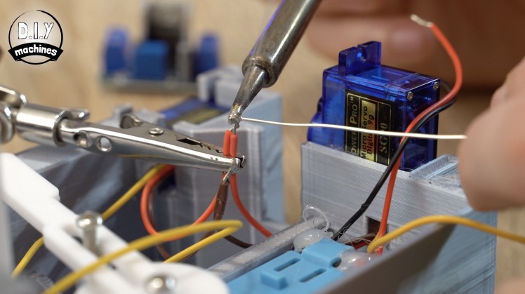
Step 15: Servo Signal Wires
For this step will you need:
- Some wire
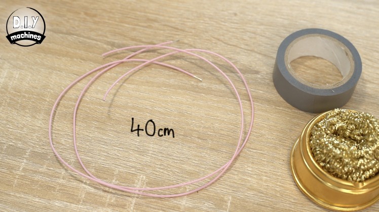
To extend the length of the orange signal wires coming from our servos add two new 40cm lengths of wire. Be sure to insulate the connections. To label these I used a black marker to draw a single ring around the continuous rotation carousel servo and two rings around the 180 degree steering servo.
These extended wires are then passed through down behind the bar next to the LM317 before then being threaded through the hoops in the other main body part (the one with the DC motor driver and wire connector) and then up through the tunnel where the majority of our other wires are.
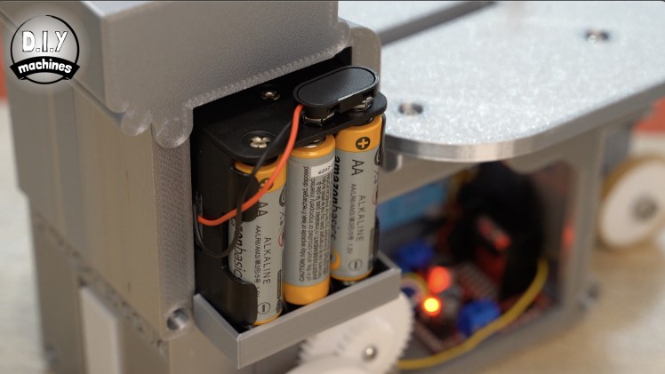
Step 16: Power Connections
For this step will you need:
- Some wire
- Battery holder case
Add a 17cm length of wire to the negative terminal on the battery holder. Route this through the hole next to where the batteries will go later. This wire is also the passed through the hoops along the top of the print and connected to the wire connector.

Whilst we are here with the soldering iron hot we can also connect the positive terminal of the battery case to the wire already waiting for connection here. This is the one coming from VCC on the DC motor driver.

Prepare a new 30cm length of wire and connect this to the wire connector with all our other ground connections. Route this through the hoops along the top and then out through the tunnel with the other wires. Label this one as Ground
Take the input ground and power connection wires for the LM317 and connect this to the GND and VCC connection on the DC motor driver. These two terminals on the motor driver will already have a wire in them - the ones going to the LM317 will be joining them.
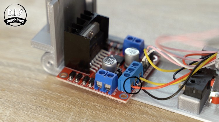
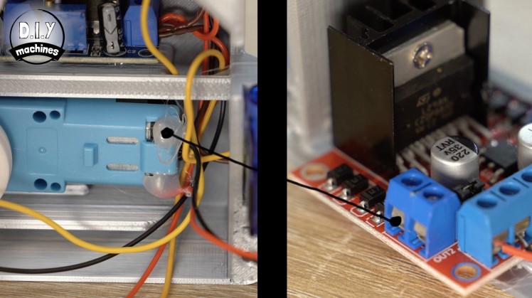
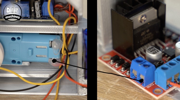
The power leads for the DC motor itself also need connecting to its driver board. The top wire on the motor should be connected to 'OUT1' on the driver board and the bottom wire on the motor to 'OUT2' on the driver board.
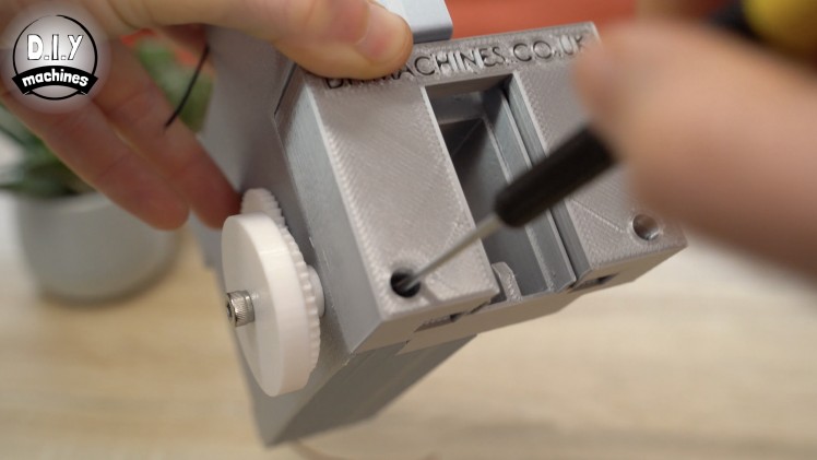
Step 17: Bringing It Together
For this step will you need:
- M3 x 10mm bolts
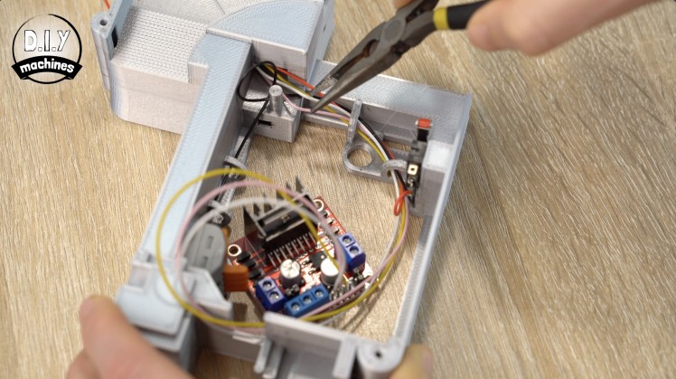
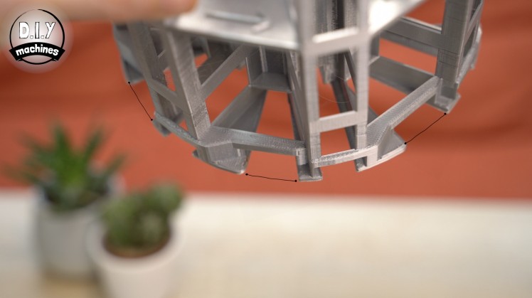
Start to bring the two halves of the body together whilst ensuring you don't trap any of the wires. There is a 'false floor' under the DC motor which can be used to fold/tuck excess wire into to keep it away from our mechanisms which will be moving later. Also make sure that the square axle passes through its corresponding hole in the opposite side of the body as it closes.
Use five M3 x10 bolts through the five access holes in the side of the body to join the two halves tightly together.
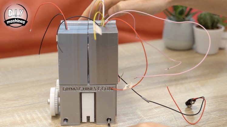
An additional two bolts are added through the domino exit part at the back and from underneath to complete this step.
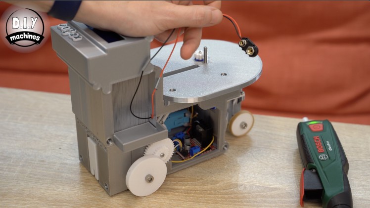
Step 18: Finishing the Drive Wheels

For this step will you need:
- M3 x 10mm (x1)
- M5 x 20mm (x1)
- 3D Printed parts:
Similarly to what we did on the other side of the main body we can use an M3x10mm bolt to attach the DriveGear to the end of the square axle ensuring that we don't tighten it so much as to create to much friction between the cog and the main body of the machine.
This is then followed by the M5x20mm bolt which us used to hold the wheel itself in place. Again, this needs to be tight enough to stop the wheel from wobbling too much but not so tight as to not be able to turn freely.
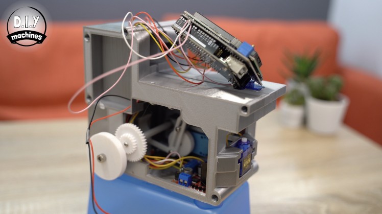
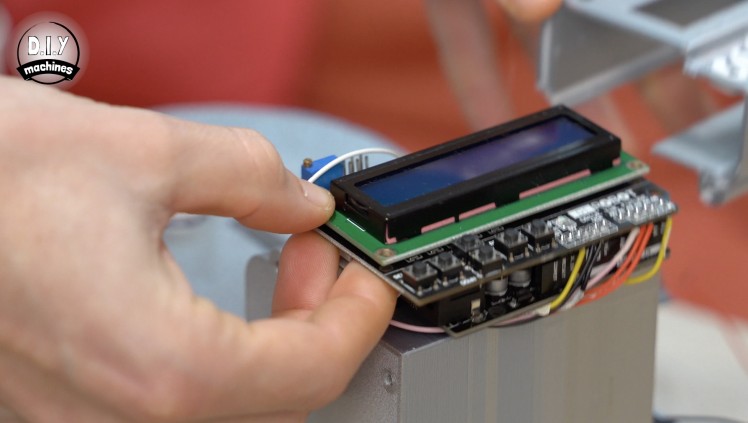
Step 19: Adding the Arduino, LCD & Buttons
For this step will you need:
- LCD Display Shield
We will solder the various wires which we sent through the tunnel to the LCD display which will then in turn connect to the pins on the Arduino when we mount the display shield on top of the Arduino shortly. I have re-attached the wiring diagram for easy reference.
It's rather wordy and I don't think very helpful for me to explain this to you in written form. So I'll provide the best two method I can for this step.
1: Using the wiring diagram.
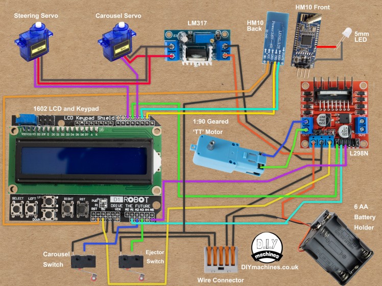
You only need to concern yourself with connecting the following component on the diagram to their correct connection on the LCD shield. the other item we will worry about later:
- Carousel servo
- Steering Servo
- Ejector Switch
- Carousel Switch
- Wire connector
- L298N Motor Driver
2: Video
This embed of the video will take you straight to the section (16:07) on wiring the same wires.
Once the wires have been soldered, the LCD display shield can then be added to the top of the Arduino Uno by carefully aligning the pins and then firmly but cautiously pressing them together.
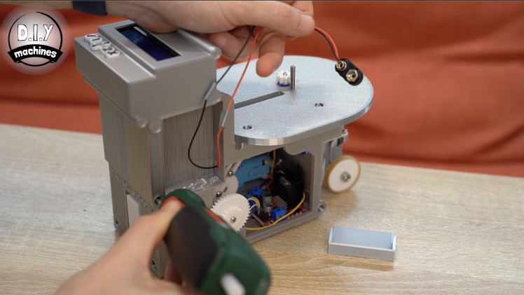
Step 20: Upload the Code for Testing
We will be adding a housing to tidy up the electronics later - don't worry about it not looking very tidy just yet. Before we do that we will upload the code to the Arduino so that we can test our wiring so far.
Whilst we do the testing I recommend raising the machine slightly so that its two main wheels are up off the ground. Whilst we test it, the machine is going to try and drive forward and backwards and this will help to prevent any accidents - such is it taking a misguided leap of faith from your desktop. :/
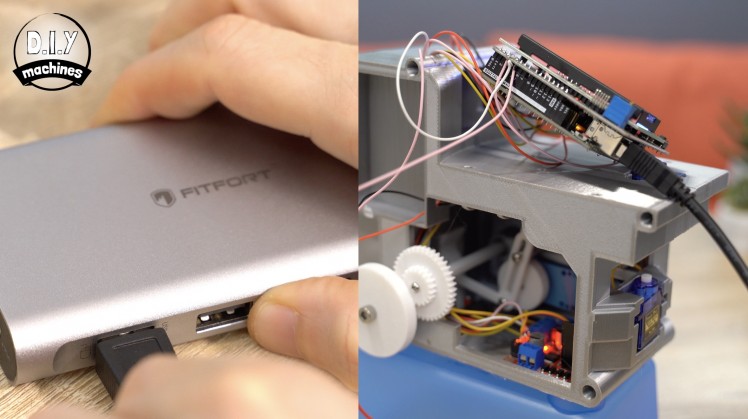
Connect your Arduino to your PC with a USB cable. Open the code for this project in the Arduino IDE.
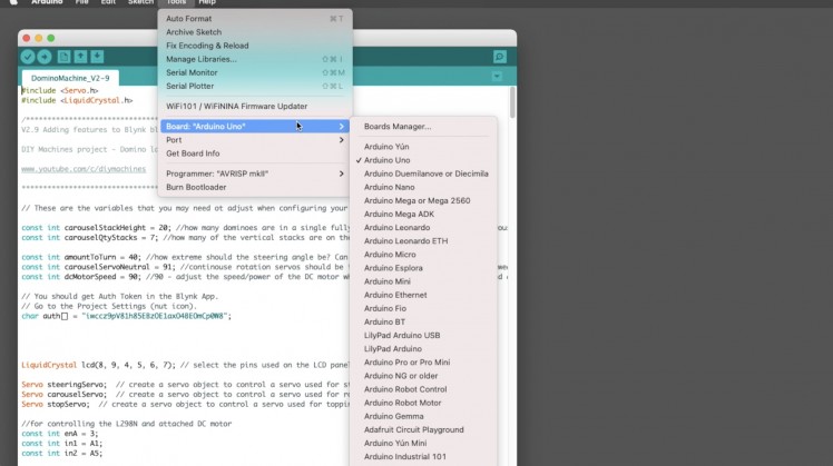
The code can be downloaded from here: https://www.diymachines.co.uk/rc-domino-laying-machine
If you don't already have the free Arduino IDE, that can be downloaded here: https://www.arduino.cc/en/software
Once the code is open, select the correct board type (Arduino Uno) and port from the tools option in the menu bar at the top of the IDE before pressing upload.
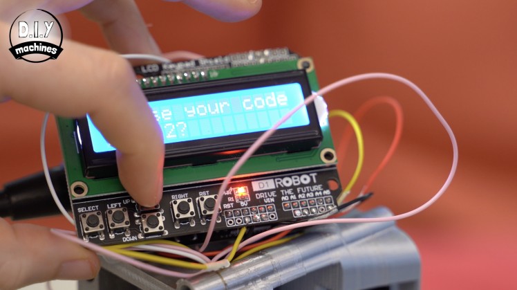
Step 21: Adjust the Display
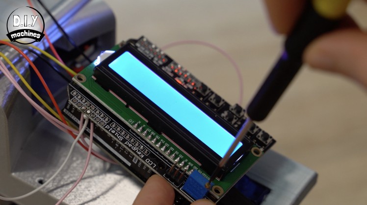
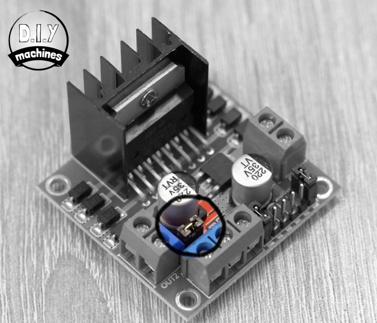
If all goes well you should see the LCD displays light up, but don't panic if you cannot read anything just yet.

If you cannot read any characters it is most likely that you need to adjust the contrast of the screen using the small screw on the top of the blue potentiometer in the corner of the shield. It may take many more turns than you expect before the text becomes legible.
Step 22: Word of Warning...
It is bad for the heath of your Arduino to connect the USB port and our batteries (which connect via the 5v pin) at the same time. Disconnect one before connecting the other at all times.
Step 23: Test the Components
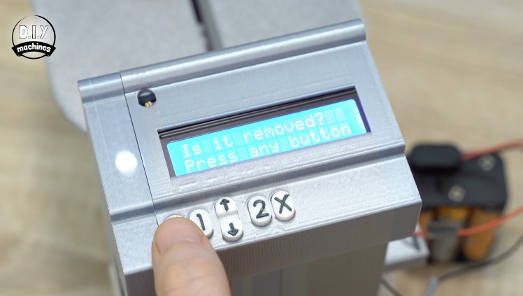
We can now disconnect the USB and connect the batteries.

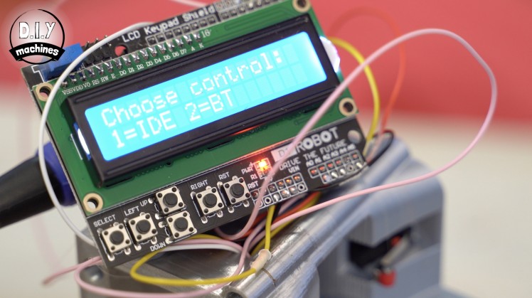
The screen should light up just as before. It will ask you to remove the carousel and then confirm it is not there. We haven't got as far as adding it yet so we can press the select button.
This will cause the DC motor to turn, which will cause the two drive wheel to turn in an attempt to drive the machine forwards (hence why we raised it during testing on a box or similar). The long domino retrieving arm will try to hook a nonexistent domino from the top of the machine and the ejector mechanism at the back will move also.
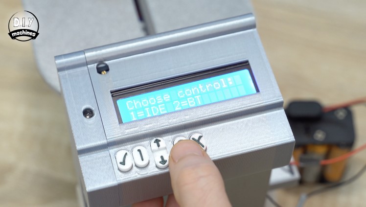
Once this movement of the back domino ejector mechanism hits the contact switch at the bottom of the machine it will bounce back slightly and then everything should stop whilst the machine awaits its next command. Select IDE by pressing the key labelled 'left' . Later we will be adding new labels to this so the menu system will make more sense then.
Once pressed the display should say 'Spinning carousel...' and the top servo should begin rotating anti-clockwise. Pressing the contact switch should cause this to stop and then rotate briefly in a clockwise direction.
Fo our last test at this stage, press the up arrow on the keypad. The carousel servo will begin turning again as before so you will need to manually click the limit switch. We should then see the machine try and dispense some dominoes before turning the steering servo and continuing to dispense. Towards the end of this program it will run the domino laying/ driving wheel backwards.
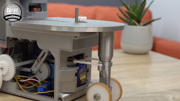
Step 24: Adding the Wheel Support
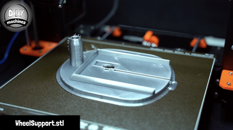
For this step will you need:
- 3D printed parts:
- WheelSupport.stl
- CarouselInnerGear.stl
- M5 x 25mm bolt
- M3 x 10mm bolts
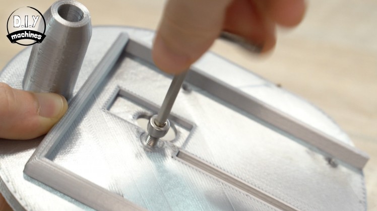
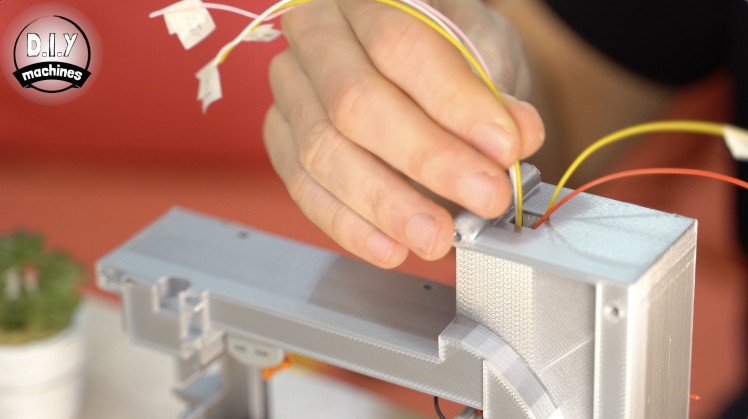
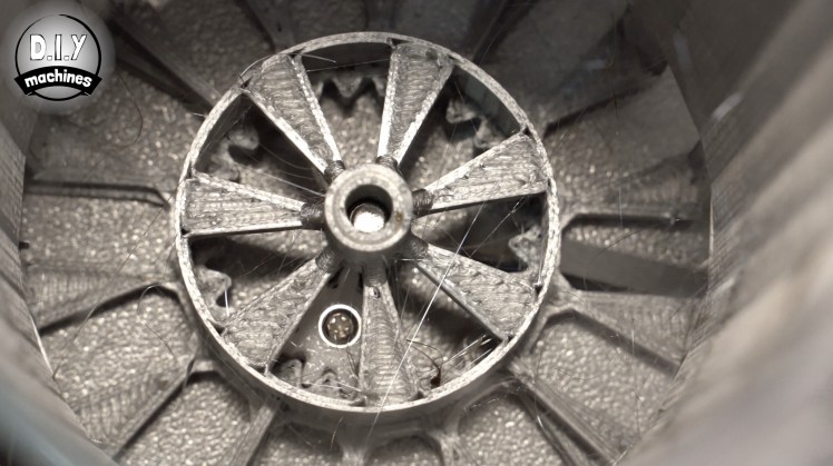
From the underside of the WheelSupport insert the M5x25mm bolts and tighten it all the way firmly.
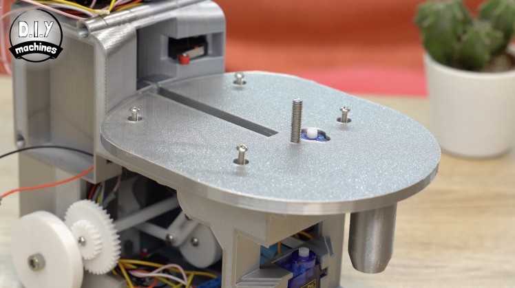
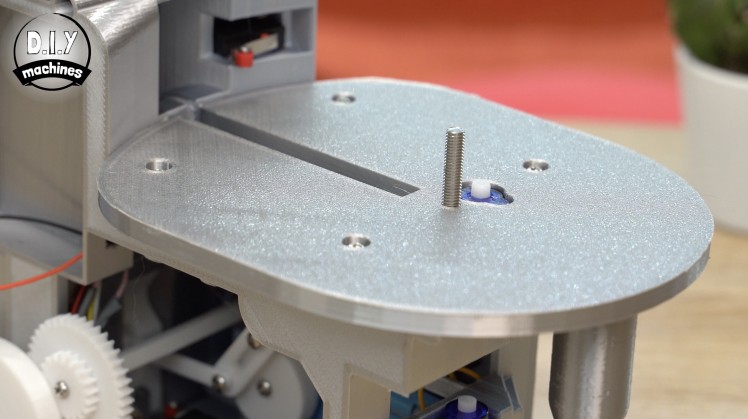
Fit the WheelSupport onto the top of our domino machine and secure it down tightly with four M3 x 10mm bolts.

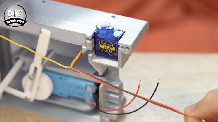
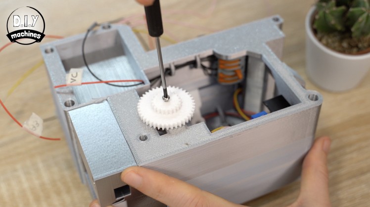
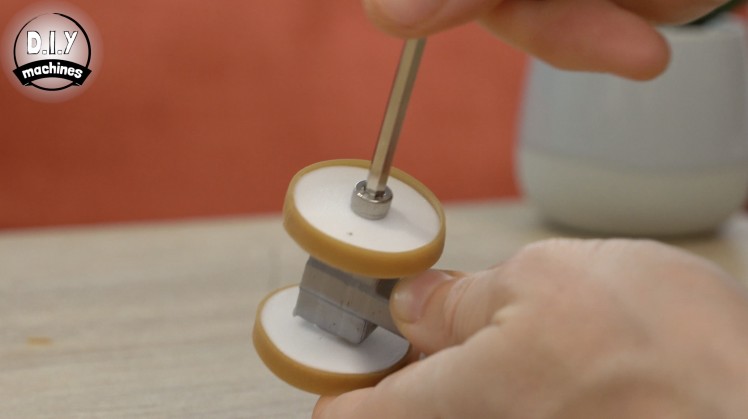
The CarouselInnerGear is then fitted onto of the servo and can be secured in place with one of the sharp screws included with your servo hardware.
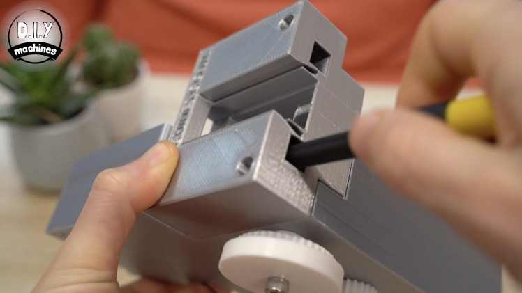
Step 25: Fitting the Steering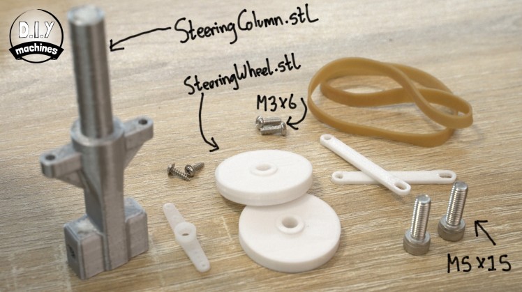
For this step will you need:
- Some 3D printed parts:
- SteeringColumn.stl
- SteeringWheel.stl (x2)
- SteeringControlArm.stl (x2)
- Rubber band
- M3 x 6mm bolts (x2)
- M5 x 15mm bolts (x2)
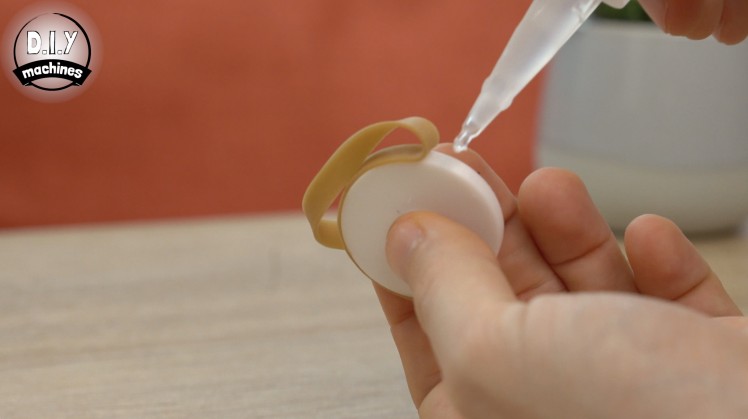
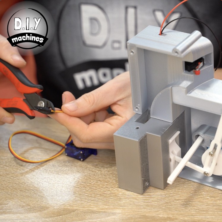
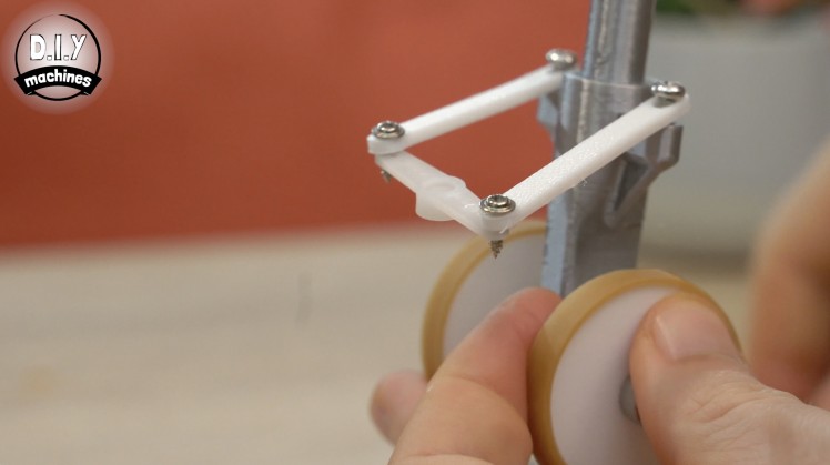
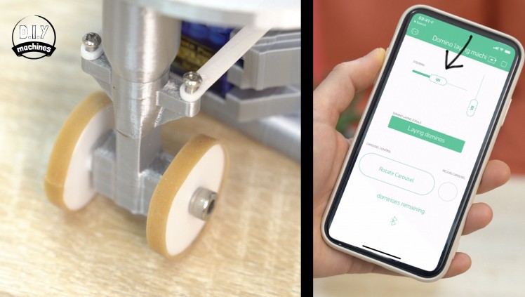
Use some super glue to attach a length of rubber band around the outside of each of the wheels. This is to enhance their grip on the floor when we try to turn tight circles.
The two wheel can then be added onto the main steering column with the two M5 x 15mm bolts. The side of the wheels with the smaller protruding shaft should be facing inwards. This helps space the main wheel and rubber band away from the shaft so as to reduce friction. Don't forget not to over tighten the bolts - these are supposed to be wheels, not skids. :)
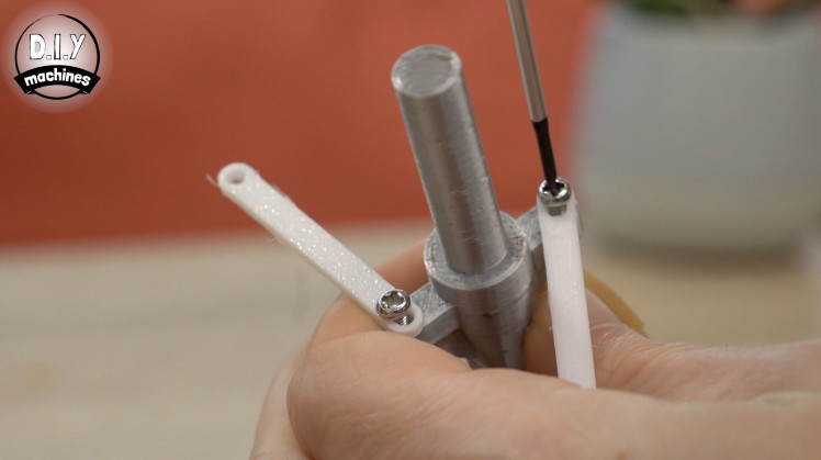
Use the two M3 bolts to secure the oval slotted ends of the steering arms to the top side of our steering post. The oval ends allow a little play in our steering mechanism which helps to stop the servo from continuously fighting itself.
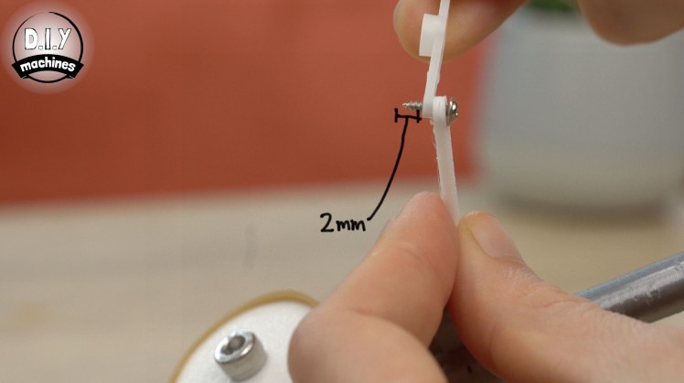
The other end of our steering arms should be attached to straight servo horn. Attach it to the outermost holes on each side of the horn using the small screws which would have been supplied with your servo hardware. You will need to screw them in until about 2mm of the screw is showing on the other side - this is to allow them to pass through the letterbox like cutout just behind the steering servo when it rotates.
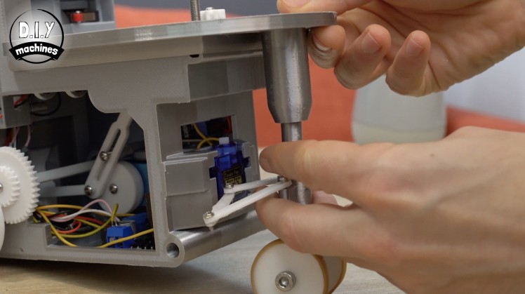
As we have been running the code for our project on the Arduino you should expect to find the steering servo has been left in the neutral position which is going to be forward for a our steering. Slide the main post of the steering assembly into the tube coming from the platform. The servo horn can then be push fitted onto the servo whilst ensuring the wheel are pointing as straight forwards as possible.
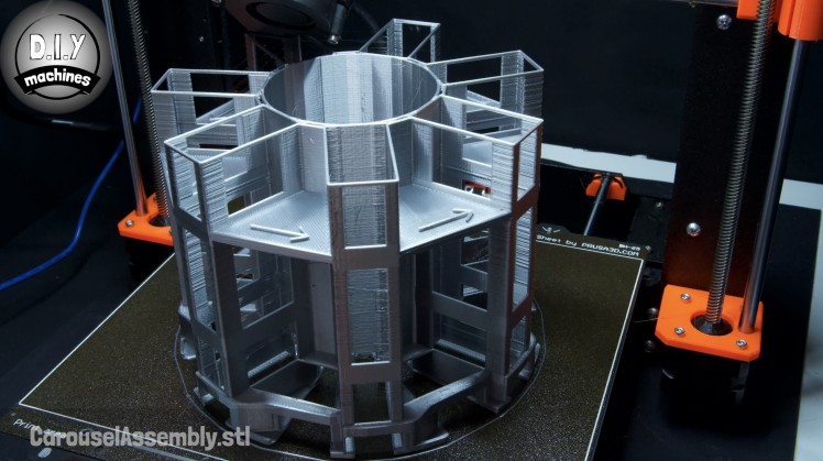
Step 26: Adding the Carousel
We can now make some progress with our carousel.
For this step will you need:
- Some 3D printed parts:
- CarouselAssembly.stl
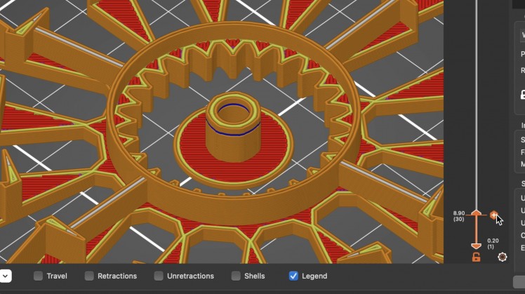
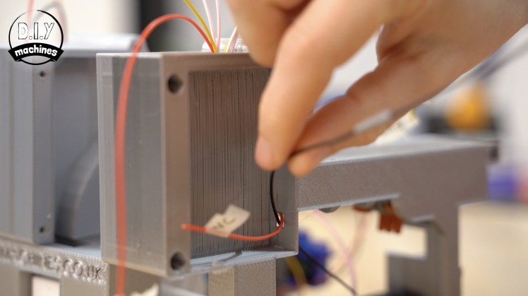
When printing this part you do not need to have your slicer add any supports. There is however a temporary support included in the actual model file.To ensure this works, check that your slicing software is going to leave a gap (shown in dark blue in the image above) during the 1st cm or so of the print in the main central column (inside the ring of gear teeth).
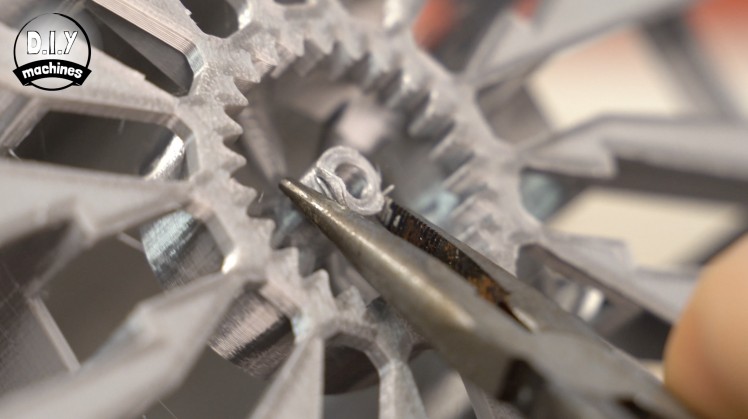
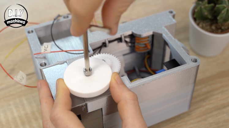
Invert the part once it has printed and snap of this support using some pliers.


This can then be lowered onto the bolt on the platform whilst taking care not to damage the contact switch by passing it through one of the large gaps around the perimeter of the model.
Step 27: Bonus Printable Parts
I created a 3D printable rapid reloading tool to help make refilling the carousel easier and quicker. There are also some additional fun accessories such as a domino bridge which you can 3D print.
These can be downloaded in exchange for a donation to the project fund. :)
They are not required to be able to make this project - they're optional. But if you would like them or would like to support my next project please consider it. They can be found here: https://diy-machines.selz.com/item/rapid-domino-reloader-and-fun-accessories-to-print
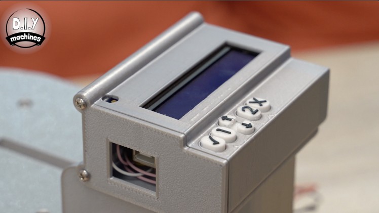
Step 28: Encasing the Electronics
For this step will you need:
- 3D Printed parts:
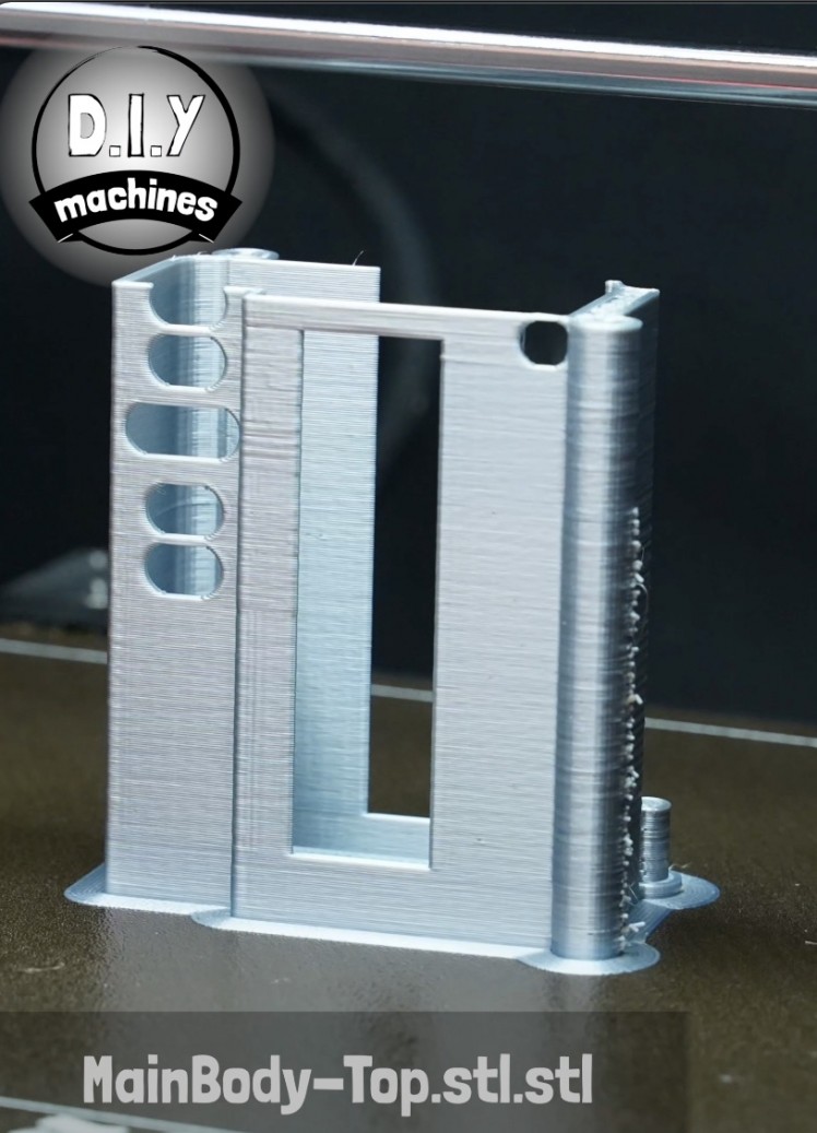
- MainBody-Top.stl
- Buttons - I printed these in white and then switched to black filament for the last two layers.
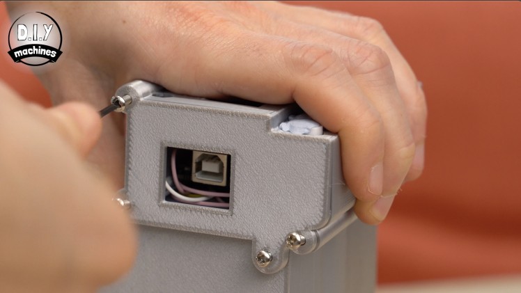
- Lid - There is a choice of two lids, one has an opening to allow continued access to the USB port of the Arduino.

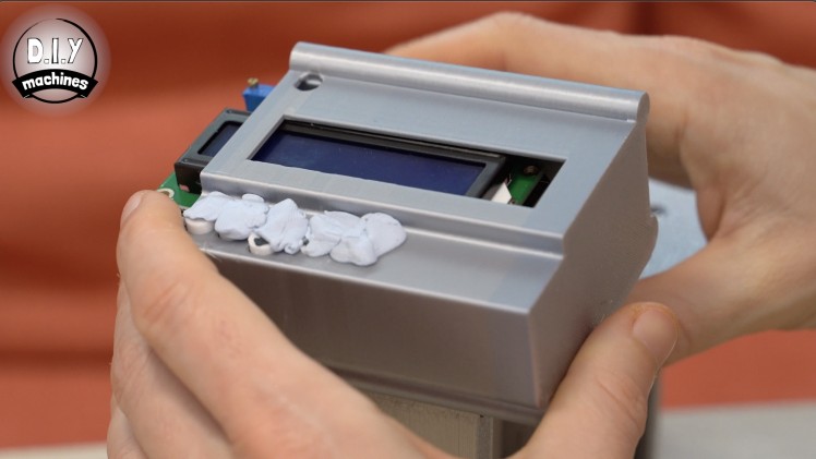
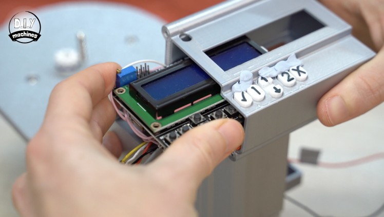
To help tidy up the electronics of our project we can print a case to house the Arduino and the LCD display.
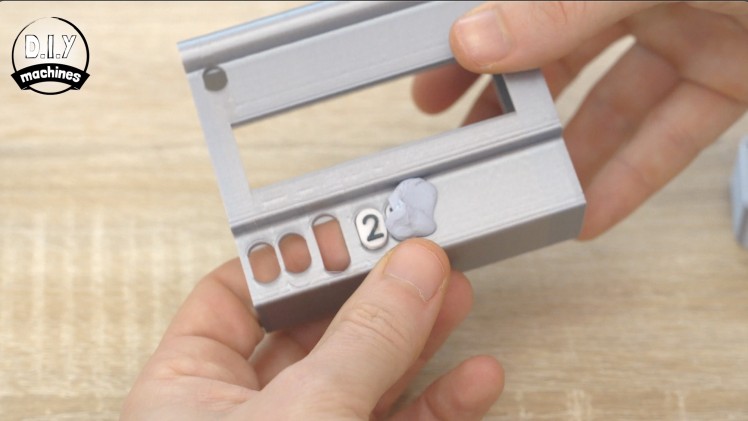
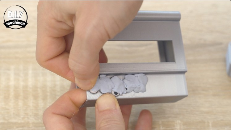
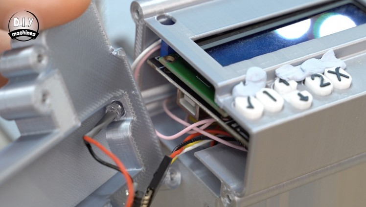
To make fitting the buttons easier, insert them from inside the case and use some bluetack to hold them upwards. This will prevent them from catching the electronics when we slide them into the case. With care, slide the electronics assembly into the case, check as you go that you are not catching any wires.
The two posts at the end of the print are designed to fit into the screw holes to hold the case in position at this end of the project.
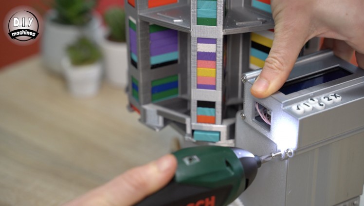
You can then use four M3 x 10mm bolts to fit your lid of choice at the other end. Two of the bolts attach the lid to the case and the other two bolts fix this case assembly firmly to the rest of the body.
The bluetack is then removed from the buttons. Use more bluetack and dab it on any remaining bluetack to help remove it.
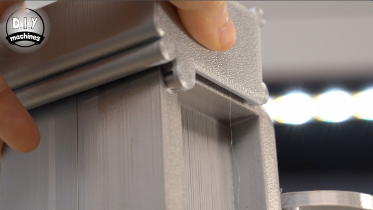
Step 29: Fit the Battery Platform
The last printed piece we need is the battery platform which is simply glued into place.
Step 30: The Fluffy Velcro
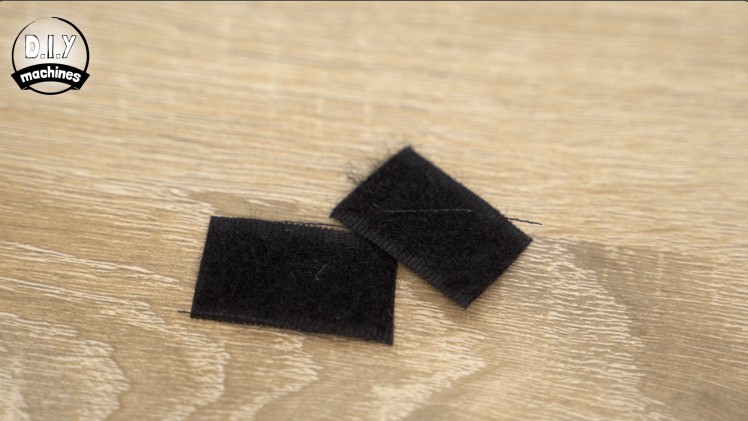
You may find yourself wondering what the fluffy side of a velcro strip was required for?

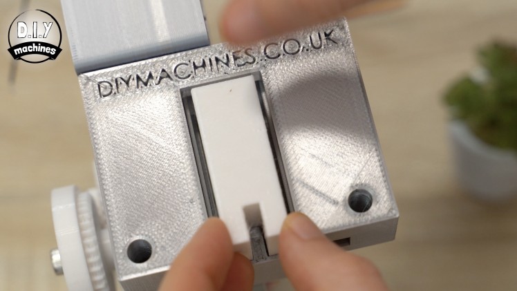
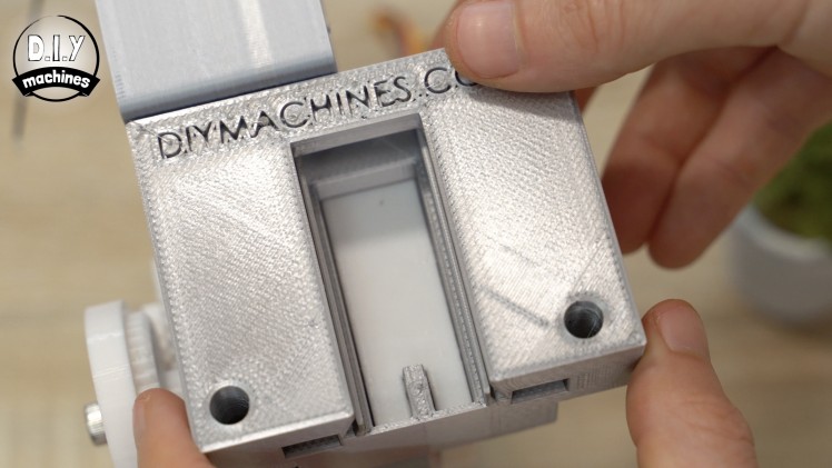
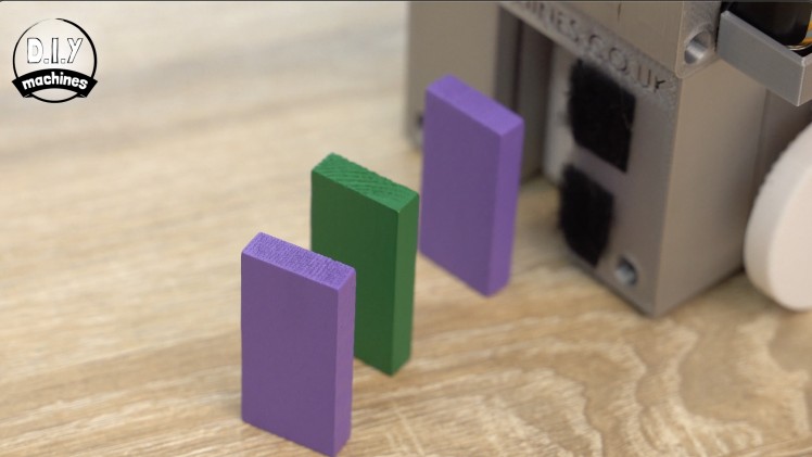
Well, if you find that your dominoes are freely toppling as they exit the rear of the machine you can cut a short length of this fluffy velcro strip and slid it into the slot from the underside of the machine where the dominoes exit - fold it back around the exit and use some glue to hold it in place. This will create some light resistance and help prevent them from toppling.
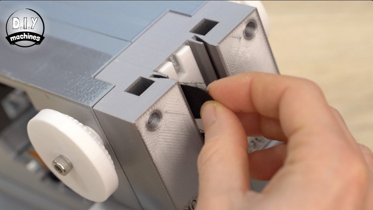
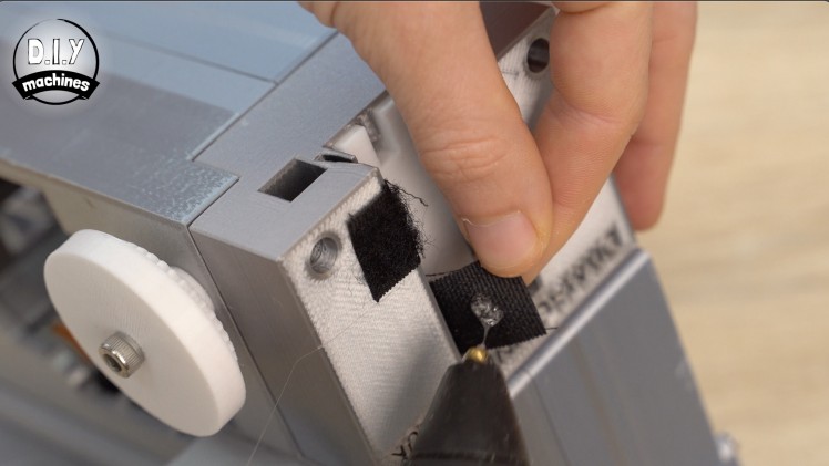
I recommend adding two strips both on the same side and trying your machine again. If they still topple then you can add two strips in the same fashion but on the opposite side of the exit.
Step 31: Programming Domino Layouts
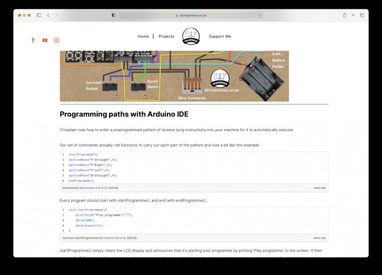
Head over to https://www.diymachines.co.uk/rc-domino-laying-machine where I have written out thorough easy to follow step-by-step instructions on how to program your very own layouts into your domino laying machine.
I have put the programming instructions for this project on my site so that if the code / programming instructions need revisions I can keep them up-to-date in a single place. Easier for me and better for you. :)
To find out how to add the optional bluetooth connectivity and set up control of your robot from your phone continue reading on....
Step 32: Adding Bluetooth App Control
This part of the project is also optional which is why it is covered in a separate video. As it stands your project is fully working and can be programmed from the Arduino IDE. If you want to drive it around using an app on your phone via a bluetooth connection then keep reading.
I have written all the steps out for the addition of bluetooth - keep reading for this. I also created a video specifically covering this bluetooth upgrade which can be found here:
Step 33: Prepare for the Upgrade
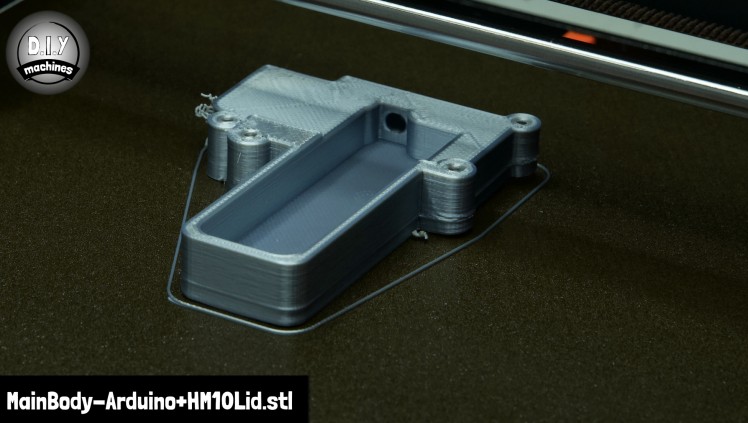
As part of the BT upgrade we will be replacing the current lid on our electronics enclosure with a new 3D printed one which has space to house our LED and HM10 module.
I printed mine in the same silver PLA as the rest of the machine. No supports are neccasary.
You can then remove the existing lid and save the four M3 bolts for use later. Slide the electronics out from inside the case as well - which we will be using later again also.
Step 34: Prepare the Wires
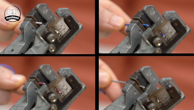
There are three ways you can create wires for this stage of the project. Here they are listed in order of the most favourable to the least favourable. The order is what it is because we will be connecting some of the wires to the serial pins on our Arduino Uno. These are the same pins used by the Arduino to talk to our PC via USB. If we leave the wires connected to the HM10 whilst we try to upload a program to the Arduino it's likely to interfere with this communication which may result in a failed upload. Using a Dupont style connector makes it easy to disconnect and reconnect the wires when we need to.
1: Create your own wires by crimping your own connector.
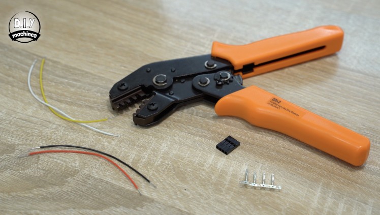
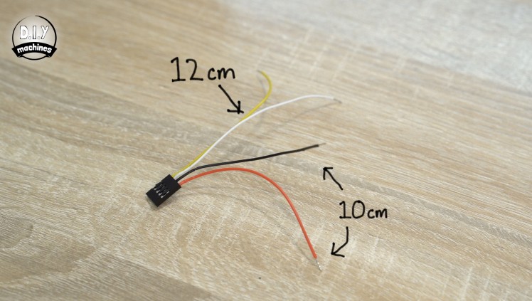
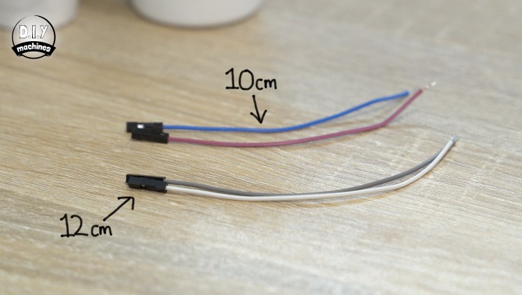
We need to create a wire connector with four wires in one single row. Two 10cm long on one side and two 12cm long on the other. (First two photos above)
If you want to crimp your own it's actually very easy. I made a video explaining how easy which you can watch here if you would like to:
2: Sacrifice four jumper/breadboard wires.
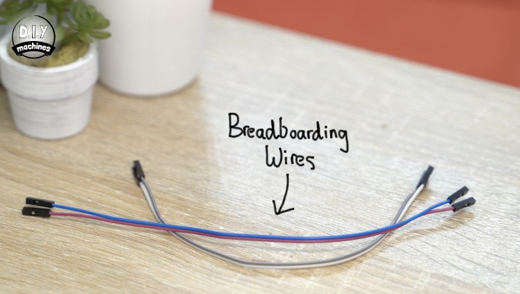
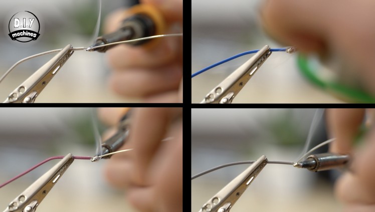
If you don't want to make your own and don't mind sacrificing four jumper wires with a female connector on at least one end, then you can cut two down to 10cm in length and two down to 12cm in length. The other ends of this wires should then be stripped and tinned ready for soldering later.
3: Solder directly to the module.
This really is the worst of the three ideas. So bad I didn't even do it to photograph for you. :)
In all honestly, I did this whilst prototyping and the problems were hit and miss. Avoid this method if you can though.
Step 35: Soldering to the Project
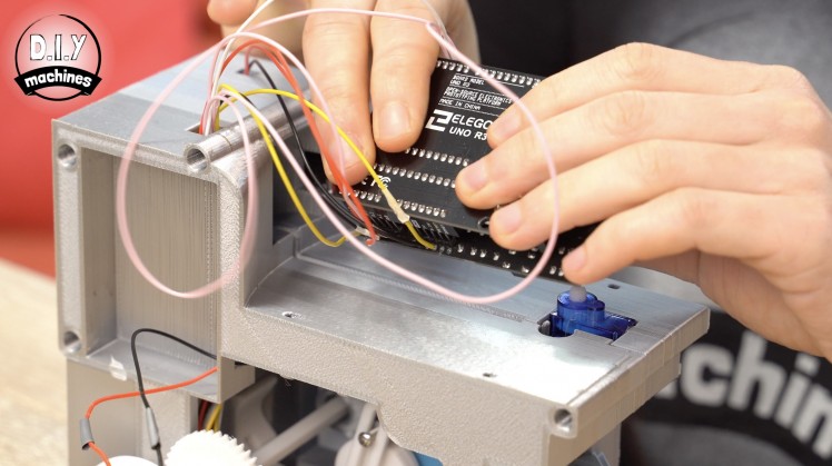
The wires we just made in the previous step are connected to the Arduinos pins via the LCD display. Pass the wires up from underneath and solder them on the top side to ensure the case will still fit our electronics.
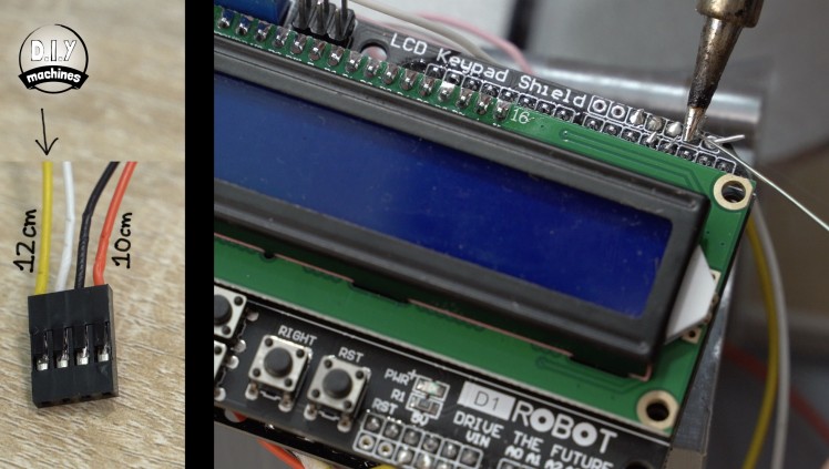
- The outside 12cm wire is soldered to the transmit pin. This is the second pin in from the top right of the display shield.

- The inner 12cm wire is soldered to the receiving pin which the is the very top right pin.

- The outermost 10cm wire on the connector is soldered to 3.3v which is the second pin in from the bottom row left this time.
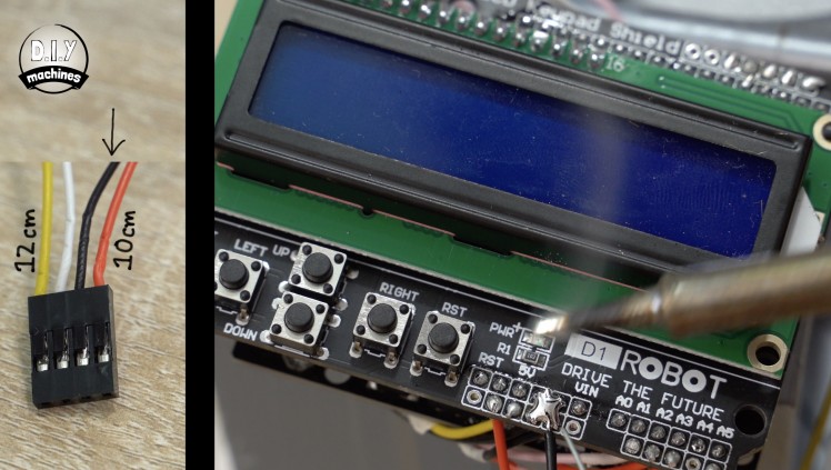
- The final wire is connected to ground. These are the four pins between the ones marked as 5v and VIN on the board.
Step 36: Preparing the LED
For this step will you need:
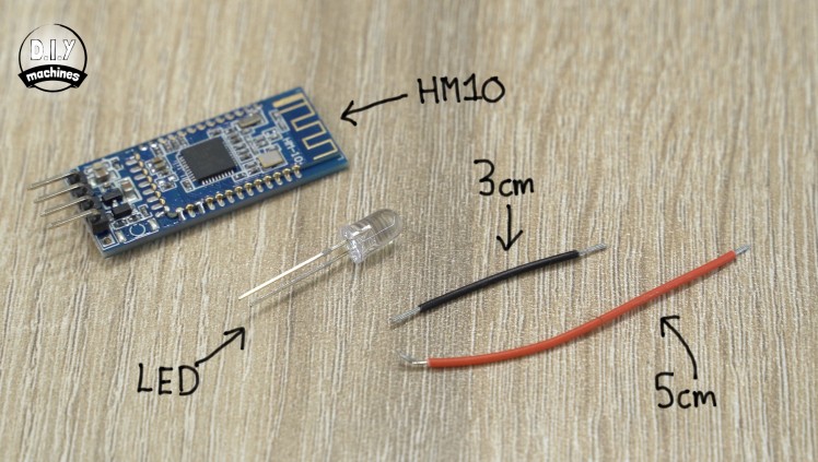
- HM10 Bluetooth module
- An LED
- Wires (3cm and 5cm long)
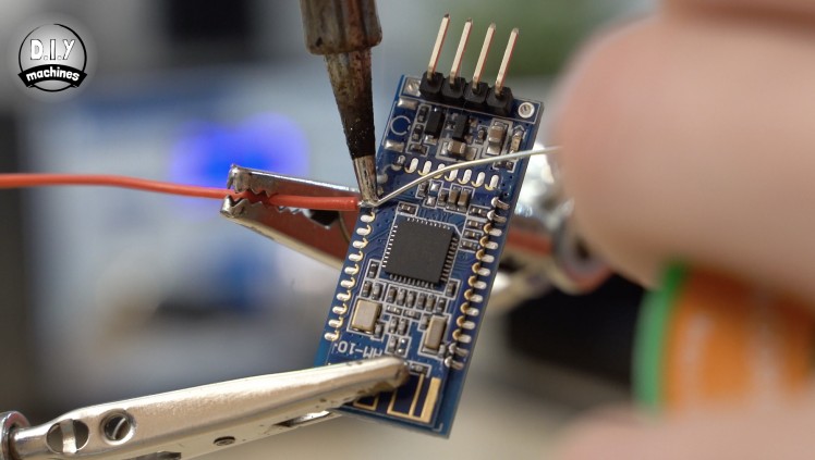

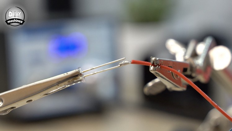
Solder the 5cm long wires to the 3rd pad down on the left of the HM10 module when looked at with the pins pointing upwards.

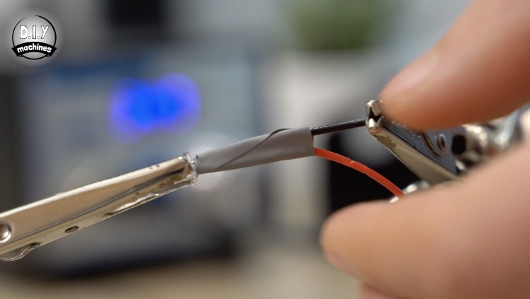
The other end of this 5cm is soldered to the positive anode of the LED. This is usually the longer leg of the two. The 3cm wire is soldered to the negative (shorter) cathode leg. Wrap some insulation around the legs to prevent them from shortening the circuit later if they touch each other.
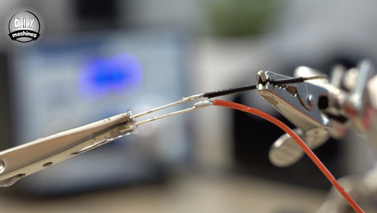
The other end of the 3cm wire is soldered to the reverse side of the ground pin on the bluetooth module. This still allows us to connect the other four wires with their connector later.
Step 37: Test the Circuit
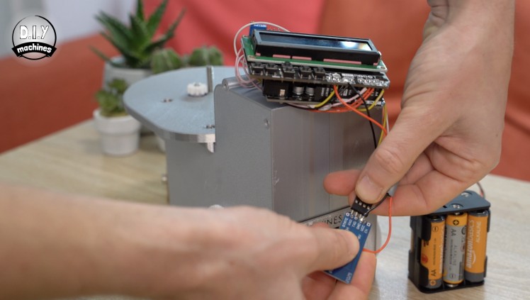
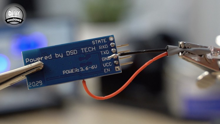
Connect the HM10 module to our set of four wires we attached to the display shield a few steps earlier. You need to make sure that the correct wires connect to the right pins. There are labels on the reverse of the bluetooth module which should help you verify this. The leg marked as VCC should be connected the Arduinos 3.3v power supply.
Connect the batteries and the tiny onboard LED as well as the one we added should start to blink in unison.
Step 38: Setting the App Up
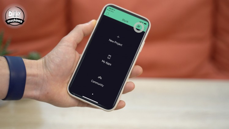
We will set up the Blynk based app on your phone next. This is because we need to upload a unique auth key the service will generate for your project before we reconnect the HM10 module and fit the electronics back into their housing.
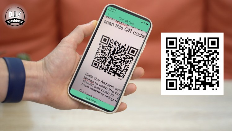
Install Blynk from your App Store. Open the app and if you already do not have a free account you will need to create one. Once this is done and your are logged in press the QR code scanner button in the top right of the main window. You can then scan the QR code found above.
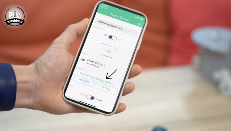
Head to the settings page of the app which will have now loaded itself onto your device and copy the AUTH TOKEN.
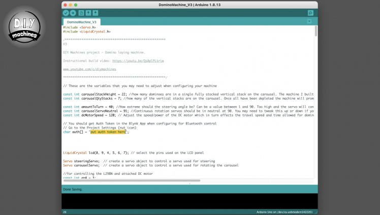
Open the project code in the Arduino IDE which we used earlier and paste your auth code into the area marked for it. Connect a USB cable between your PC and Arduino and then re-upload the projects code.
The USB cable can then be disconnected and the HM10 module reconnected. Don't forget to pay attention to the orientation of the wires.
Step 39: Reassemble the Machine
The electronics can now be re-inserted into the display housing. As before you can use some Blue-tack to hold the buttons into place temporarily. The wires for the new HM10 module should be passed underneath the Arduino.
Insert the LED into it's hole from the inside of our new lid. It should just push fit into place, if not, you can use some glue to help hold it into position.
The lid is secured using the four M3 bolts we put to one side earlier.

Step 40: Connecting the App
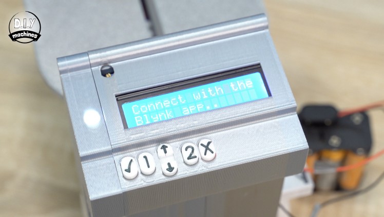
Connect the batteries and then confirm that the carousel has been removed (assuming you have of course).
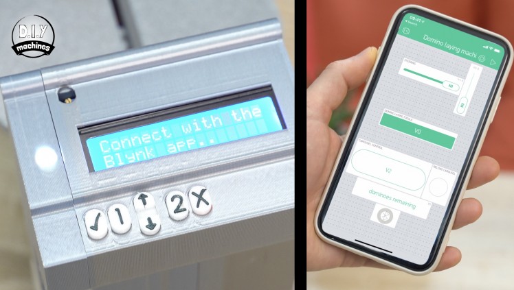
Choose option 2 for bluetooth control. The machine will prompt you to connect the Blynk app.
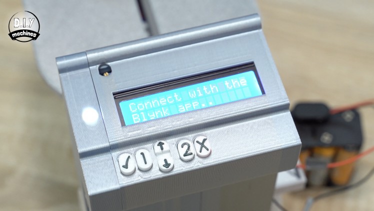
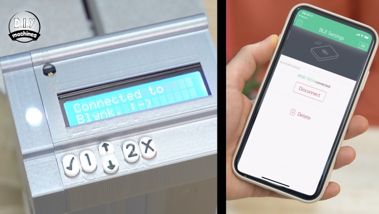
Open the app on your phone and press the bluetooth icon at the bottom of the app when the app is in 'not running' mode. By which I mean you have not pressed the play button at the top yet. Press 'Connect BLE Device' which will show you a list of available near by devices. Mine is called DSD-TECH so I will select that.

At this point the LED we added will change from blinking to a solid light to indicate that we have a bluetooth connection. The screen will also print 'Connected to Blynk. :) ' You can then press the play icon at the top right to begin the app.
Step 41: The Controls
Here is a brief description of the controls:
The horizontal slider controls the steering with the front servo. This can be any value along the line allowing a small or large turning radius in either direction.
The rotate carousel button... well, rotates the carousel by one position.
The reload carousel button lights up when the machine believes you have exhausted the supply of dominoes (assuming it was a fully loaded carousel when you started it).

The vertical slider controls the main driving and domino laying. Central is neutral, up for forward and down for backwards. You need to turn the domino laying off in order to be able to drive it backwards.
Step 42: Project Complete
I hope you have a good time laying down massive runs and then knocking them down. I printed two carousels so that someone could be reloading one whilst we drove the other one around - you stand a chance of keeping up with the machine this way! :)
Should you want to support my projects, please consider subscribing to me on here and Youtube. I also have a Patreon page where some very kind people are helping me to cover the cost of designing, documenting and sharing these projects. Please consider joining them in any way if you can.
Until the next project, ciao for now. Lewis
Schematics, diagrams and documents
CAD, enclosures and custom parts
Code
Credits
Related products


Leave your feedback...