
Raspberry Pi Traffic Lights Using Hexabitz Modules

Made by Aula_Jazmati / Automotive / Games & Gaming / Kids & Family / Lights / Vehicles
About the project
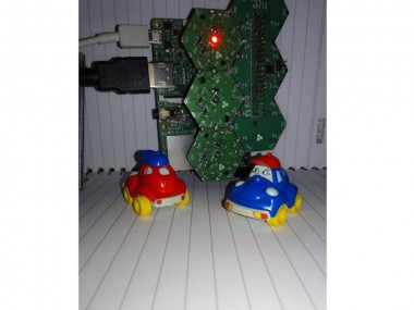
This Project demonstrates how to make a smart traffic light system using Raspberry Pi and Hexabitz modules.
Project info
Difficulty: Moderate
Platforms: Adafruit, Raspberry Pi
Estimated time: 1 hour
License: MIT license (MIT)
Items used in this project
Hardware components

Story

- This Project demonstrates how to make a smart traffic system using Raspberry Pi and Hexabitz modules.
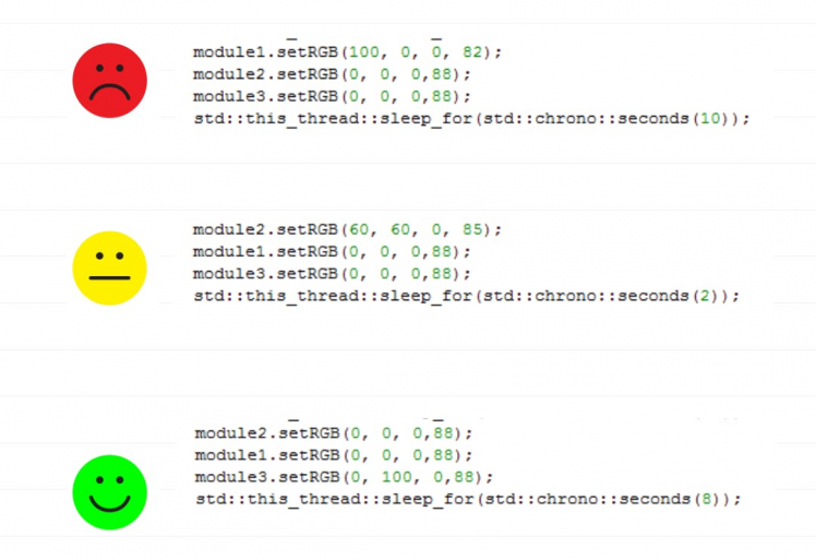
- We Learn to control traffic light LEDs and code a traffic lights sequence using C++.

1. Hexabitz modules have their own MCUs and thus can be used without an external controller. But when we use these modules with Raspberry Pi, we can design powerful electronic system.

2. Hexabitz modules can natively interface to any external hardware via array ports running UART communication. External hardware can mimic a CLI textual input or utilize a more efficient machine format (a serial, packet-based messaging protocol).
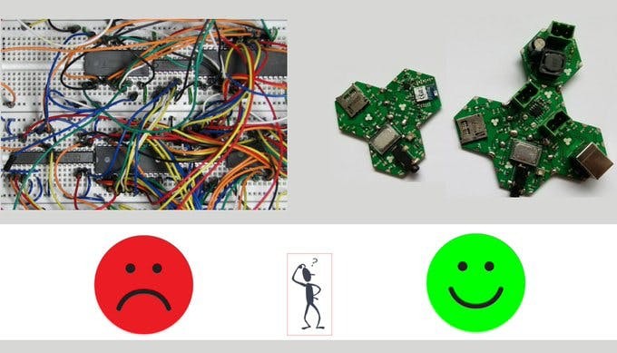
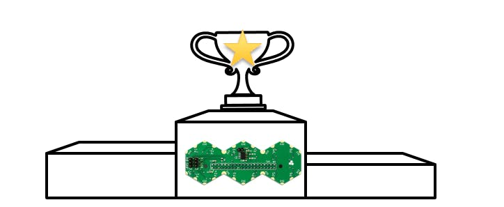
3. Hexabitz modules use a novel edge-soldering technique that eliminates the overhead of connectors and wires while providing more rigid, clean, and reliable prototypes. Save time and free yourself from the hassle of debugging wire connections. Instead, build a rigid prototype that can leave your bench and return unharmed!
4. HF1R0 module has made possible to expand Hexabitz array and also use Raspberry pi for CPU-intensive complex tasks.
5. HF1R0x interfaces seamlessly to Raspberry Pi 3B/3B+/4B single-board computers and enables you to connect and control your favorite Hexabitz modules from the Raspberry Pi operating system and build your own Raspberry Pi_Hat. This is the world’s first build-your-own-Pi-Hat system.
Hardware Design and Implementation
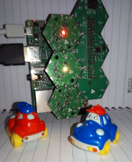
• Connect the RGB LEDs Modules to HF1R0 module.
• Take your Hexabitz array and HF1R0 module and solder them together.
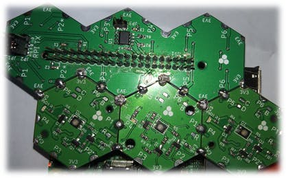
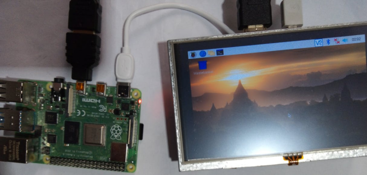
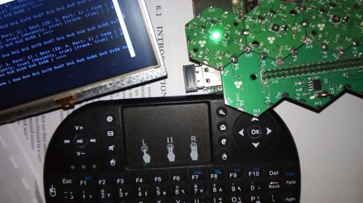
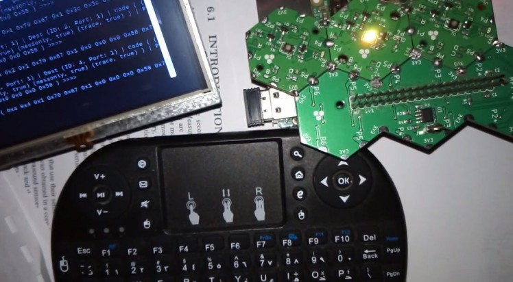
• Make sure to connect your Hexabitz array at the right spot. In this project, I have Jumper JP1 and JP2 at position 1 & 2 and my Hexabitz array is soldered between port 2 and port 3 & 5 & 6 of HF1R0 as shown in the picture below:
- Be sure to download the firmware on each module before soldering.
https://hexabitz.com/docs/how-to/update-module-firmware/
- Installing operating system -Raspbian Buster with desktop and recommended software-image and Writing an image to the SD card
https://www.raspberrypi.org/documentation/installation/installing-images/README.md

- How to setup Hexabitz Raspberry Pi 3 Interface Module Firmwarefor the first time?
sudo apt-get update
sudo apt-get upgrade
sudo apt-get install build-essential
sudo apt-get install cmake
cd ~
git clone https://github.com/HexabitzPlatform/HF1R0x-Firmware.git
cd HF1R0x-Firmware
git checkout master
rm -rf build
mkdir build
cd build
cmake..
- How to compile the repository
make
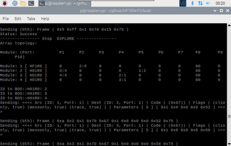
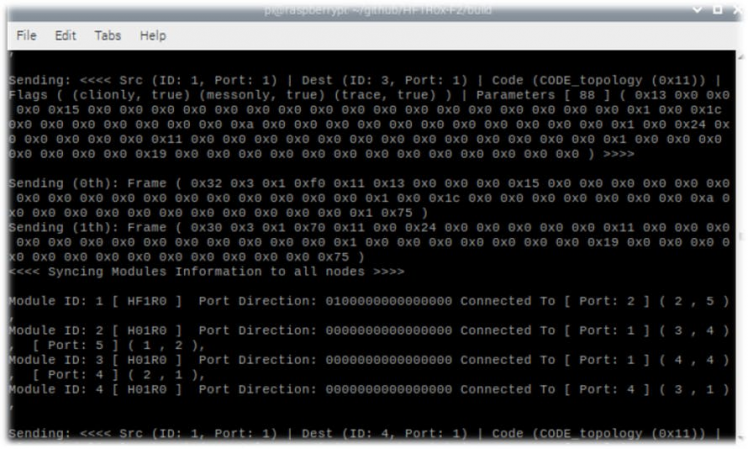
- How to run the executable
./hexabitz-demo
Building our Code using Hexabitz development libraries:
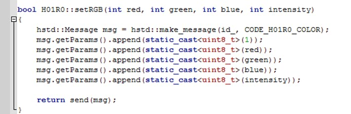
• We use setRGB function in ProxyModule.cpp in HF1R0x-Firmware/src/hexabitz folder.
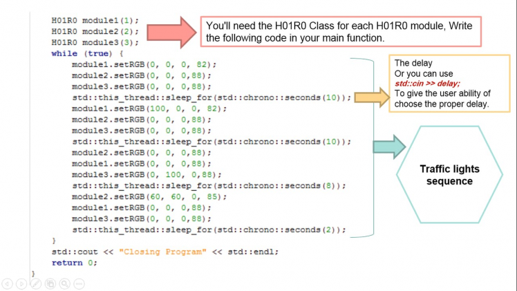
• We try repeating set this function by putting the code inside a while loop in our main code at HF1R0x-Firmware/src/tools folder:
I useGeany to modify the codes. Geany is a powerful, stable and lightweight programmer's text editor that provides tons of useful features.
Note:
You need to connect with CLI by putty program and type default array to remove the topology and restore native firmware when you decided start a new project.
1 / 4


This project is under development where we are going to add GUI to it.

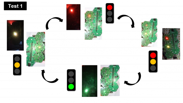
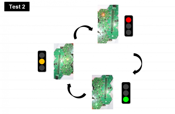
Pi 3/B Test

Schematics, diagrams and documents
Code
Credits
Related products


Leave your feedback...