
Police Lights Using Neopixel Shield For Arduino Rgb Led

About the project
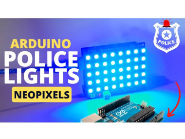
In this tutorial you will see how to make a Police Lights using the NeoPixel Shield for Arduino - 40 RGB LED Pixel Matrix.
Project info
Difficulty: Easy
Estimated time: 1 hour
License: GNU General Public License, version 3 or later (GPL3+)
Items used in this project

Story
1 / 3
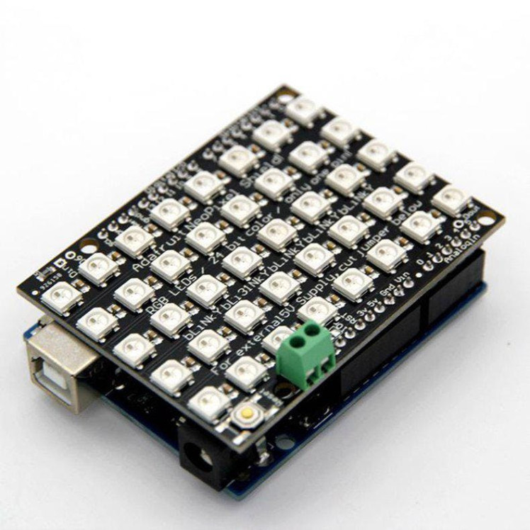
- NeoPixel Shield for Arduino - 40 RGB LED Pixel Matrix
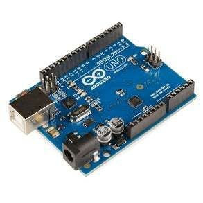
- Arduino UNO
- Visuino software: Download here

Thank you PCBWay for supporting this tutorial and helping users learn more about electronics.
What I like about the PCBWay is that you can get 10 boards for approximately $5 which is really cost effective for professional made boards, not to mention how much time you save!
Go check them out here. They also offer a lot of other stuff in case you might need it like assembly,3D printing,CNC machining and a lot more.
Step 3: The Circuit
Attach the Shield to Arduino Uno
Step 4: Start Visuino, and Select the Arduino UNO Board Type1 / 2
The Visuino: https://www.visuino.eu also needs to be installed. Download Free version or register for a Free Trial.
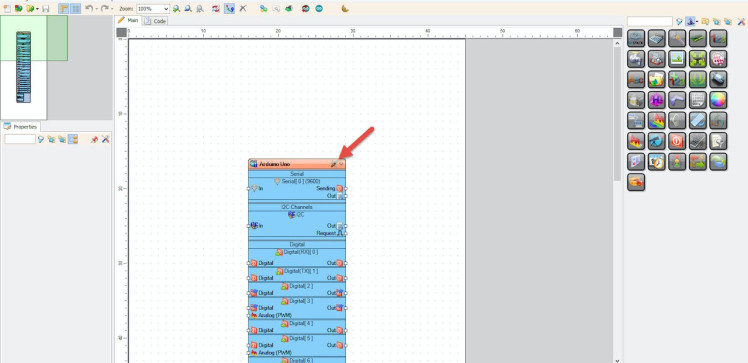
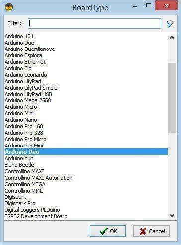
Start Visuino as shown in the first picture Click on the "Tools" button on the Arduino component (Picture 1) in Visuino When the dialog appears, select "Arduino UNO" as shown on Picture 2
Step 5: In Visuino Add Components1 / 8
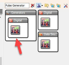

- Add "Pulse Generator" component
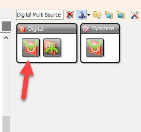
- Add "Digital Multi Source" component
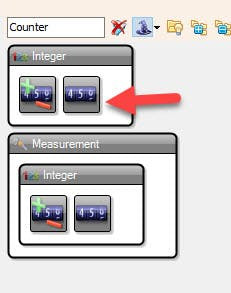
- Add "Counter" component
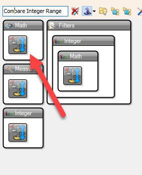
- Add "Compare Integer Range" component
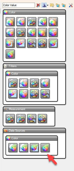
- Add 3X "Color Value" component
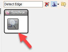
- Add "Detect Edge" component
- Add "Color Toggle Switch" component
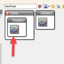
- Add "NeoPixels" component
1 / 11
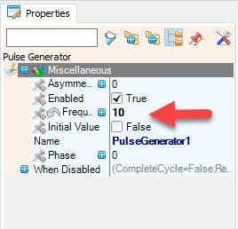

- Select "PulseGenerator1" and in the properties window set "Frequency (Hz)" to 10
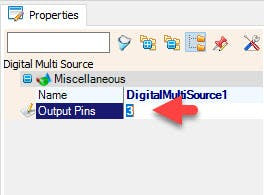
- Select "Digital Multi Source" and in the properties window set "Output Pins" to 3
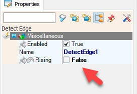
- Select "DetectEdge1" and in the properties window set "Rising" to False
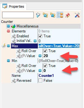
- Select "Counter" and in the properties window set "Max">"Value" to 20
- Select "Counter" and in the properties window set "Min">"Value" to 0
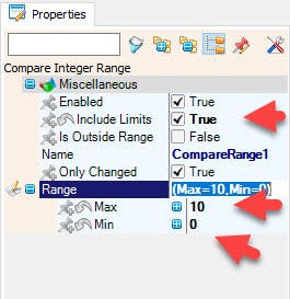
- Select "CompareRange1" and in the properties window set "Include Limits" to True and
- Select "CompareRange1" and in the properties window set "Range">"Max" to 10
- Select "CompareRange1" and in the properties window set "Range">"Min" to 0
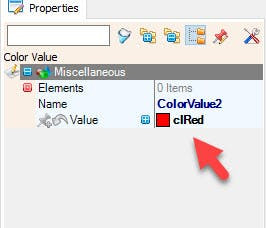
- Select "ColorValue2" and in the properties window set "Value" to clRed
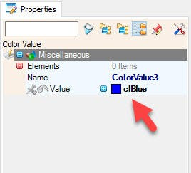
- Select "ColorValue3" and in the properties window set "Value" to clBlue
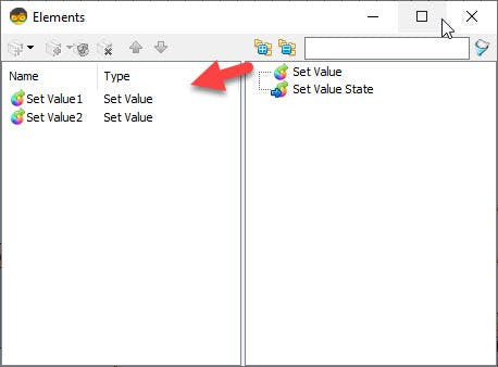
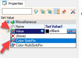
- Double click on "ColorValue1" component and in the "Elements" Drag "Set Value" to the Left and in the properties window select "Value" and click on the Pin icon and select "Color SinkPin"
- Close the "Elements" window
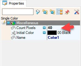
- Double click on "NeoPixels1" component and in the "PixelGroups" Drag "Single Color" drag to the Left and in the properties window set "Count Pixels" to 40
- Close the "PixelGroups" window
1 / 2
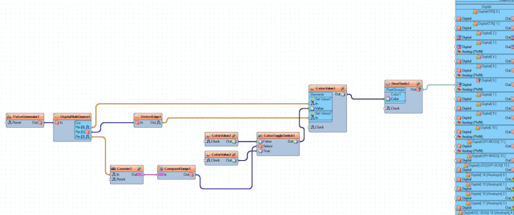
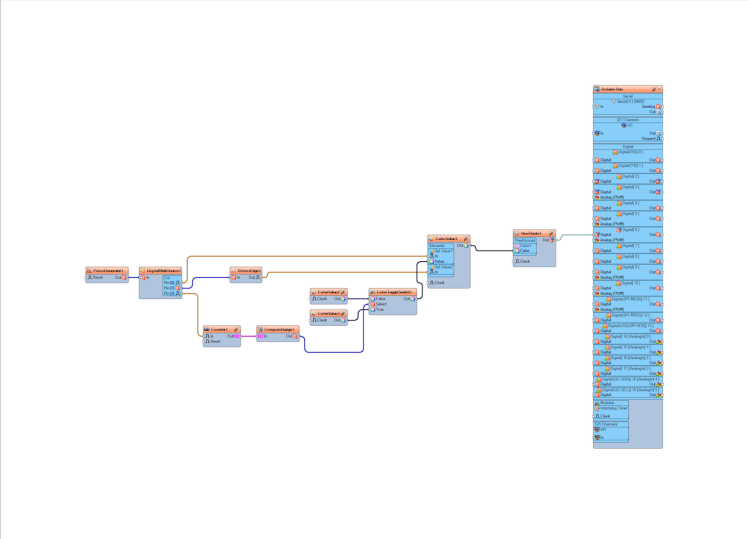
- Connect "PulseGenerator1" pin[Out] to "DigitalMultiSource1" pin[In]
- Connect "DigitalMultiSource1" pin[0] to "ColorValue1"> "Set Value1" pin[In]
- Connect "DigitalMultiSource1" pin[1] to "DetectEdge1" pin[In]
- Connect "DigitalMultiSource1" pin[2] to "Counter1" pin[In]
- Connect "DetectEdge1" pin[Out] to "ColorValue1"> "Set Value2" pin[In]
- Connect "Counter1" pin[Out] to "CompareRange1" pin[In]
- Connect "CompareRange1" pin[Out] to "ColorToggleSwitch1" pin[Select]
- Connect "ColorValue2" pin[Out] to "ColorToggleSwitch1" pin[False]
- Connect "ColorValue3" pin[Out] to "ColorToggleSwitch1" pin[True]
- Connect "ColorToggleSwitch1" pin[Out] to "ColorValue1"> "Set Value1" pin[Value]
- Connect "ColorValue1" pin[Out] "NeoPixels1" > "Color1" pin[Sensor]
- Connect "NeoPixels1" pin[Sensor] to Arduino digital pin[6]
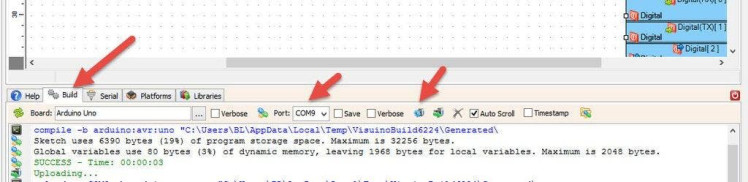
In Visuino, at the bottom click on the "Build" Tab, make sure the correct port is selected, then click on the "Compile/Build and Upload" button.
Step 9: PlayIf you power the Arduino module the LED Pixel Matrix Pixels will start to Flas a Blue and a Red color.
Congratulations! You have completed your project with Visuino. Also attached is the Visuino project, that I created for this Instructable, you can download it and open it in Visuino: https://www.visuino.eu
Schematics, diagrams and documents
Code
Credits
Related products


Leave your feedback...