

Otto Diy Robot Walking - Quick And Easy To Do Tutorial

Made by Ron / Games & Gaming / Home Automation / Robotics
About the project
In this tutorial we will learn how to easily program the Otto DIY Robot to walk. Watch a demonstration video.
Project info
Difficulty: Moderate
Estimated time: 1 hour
License: GNU General Public License, version 3 or later (GPL3+)
Items used in this project

Story
In this tutorial we will learn how to easily program the Otto DIY Robot to walk.
Watch a demonstration video.
Step 1: What You Will Need
- Otto Robot you can purchase it hereor see the instructions on how to build it in a few steps here.
- Visuino program: Download Visuino
Step 2: Start Visuino, and Select the Arduino UNO Board Type
1 / 2
To start programming the Arduino, you will need to have the Arduino IDE installed from here: https://www.arduino.cc/.
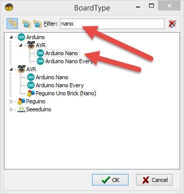
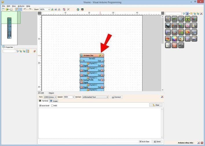
Please be aware that there are some critical bugs in Arduino IDE 1.6.6. Make sure that you install 1.6.7 or higher, otherwise this tutorial will not work! If you have not done follow the steps in this tutorial to setup the Arduino IDE to program Arduino Nano ! The Visuino: https://www.visuino.eu also needs to be installed. Start Visuino as shown in the first picture Click on the "Tools" button on the Arduino component (Picture 1) in Visuino When the dialog appears, select "Arduino UNO" as shown on Picture 2
Step 3: In Visuino Add Components
1 / 4

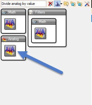

Add Components:
- Add 2X "Analoge Value" component
- Add 2X "Divide Analog By Value" component
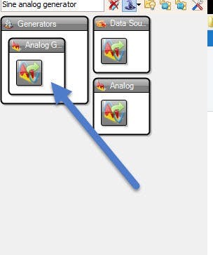
- Add 2X "Sine Analog Generator" component
- Add 2X "Servo" component
Step 4: In Visuino Set Components
1 / 5

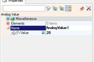
- Select "AnalogValue1" component and in the properties window set "Value" to 20
- Select "AnalogValue2" component and in the properties windowset "Value" to 20
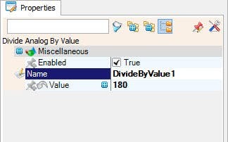
- Select "DivideByValue1" component and in the properties window set "Value" to 180
- Select "DivideByValue2" component and in the properties window set "Value" to 180
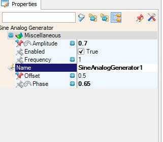
- Select "SineAnalogGenerator1" component and in the properties window set "Phase" to 0.65 and "Frequency" to 1 and "Offset" to 0.5
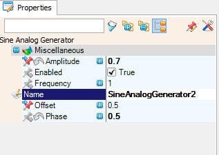
- Select "SineAnalogGenerator2" component and in the properties window set "Phase" to 0.5 and "Frequency" to 1 and "Offset" to 0.5
- Select "Servo1" and set name to "LR1" << we set this for easier understanding. This means Leg Right
- Select "Servo2" and set name to "FR1" <<This means Foot Right
- Select "Servo3" and set name to "LL1" <<This means Leg Left
- Select "Servo4" and set name to "FL1" << This means Foot Left
Step 5: In Visuino Connect Components
1 / 2
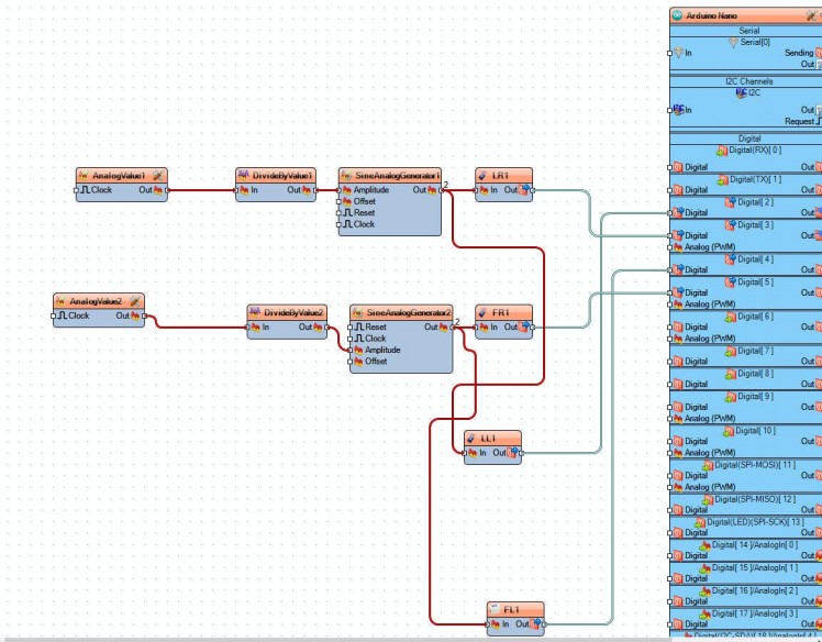
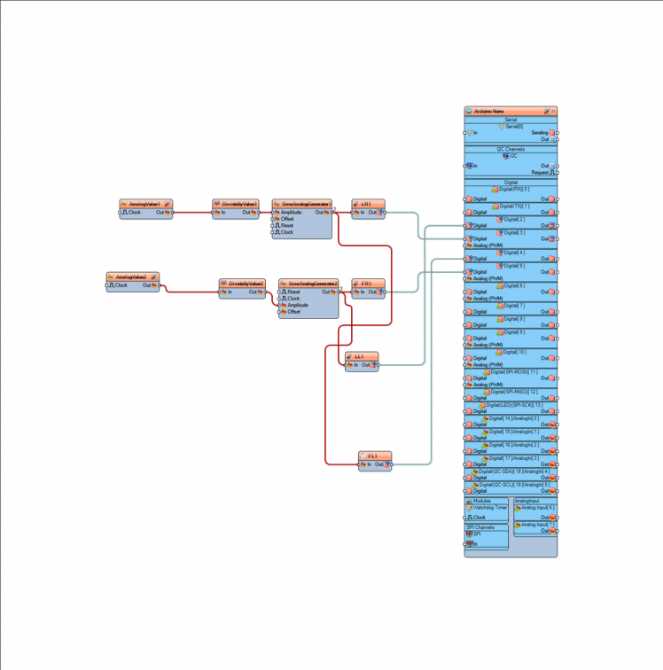
- Connect "AnalogValue1" component pin[Out] to "DivideByValue1" component pin [In]
- Connect "AnalogValue2" component pin[Out] to "DivideByValue2" component pin [In]
- Connect "DivideByValue1" component pin [Out] to "SineAnalogGenerator1" pin[Amplitude]
- Connect "DivideByValue2" component pin [Out] to "SineAnalogGenerator2" pin[Amplitude]
- Connect "SineAnalogGenerator1" pin[Out] to "LR1" component pin [In] and "LL1" component pin [In]
- Connect "SineAnalogGenerator2" pin[Out] to "FR1" component pin [In] and "FL1" component pin [In]
- Connect "LR1" component pin [Out] to Arduino Digital pin[3]
- Connect "FR1" component pin [Out] to Arduino Digital pin[5]
- Connect "LL1" component pin [Out] to Arduino Digital pin[2]
- Connect "FL1" component pin [Out] to Arduino Digital pin[4]
Note: Please check that Arduino pins[2,3,4,5] match the connections on your Servo motor shield for(leg and foot) and change them if necessary.
Step 6: Generate, Compile, and Upload the Arduino Code
1 / 3
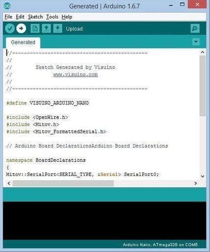
In Visuino, Press F9 or click on the button shown on Picture 1 to generate the Arduino code, and open the Arduino IDE
In the Arduino IDE:
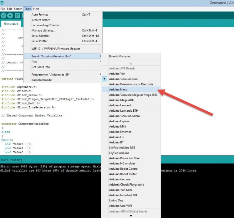
- Click on the Menu "Tools" and select the Board "Arduino Nano" (Picture 2)
- Click on the Menu "Tools" and select the Port
- Click on the Menu "Tools" and select the Port
- click on the Upload button, to compile and upload the code (Picture 3)Note: If you find some problems uploading the code you can click on the Menu Tools>Processor:..>ATMega328P (Old Bootloader)
Step 7: Play
If you power the Otto Robot, it will start to walk.
Congratulations! You have completed your Otto project with Visuino. Also attached is the Visuino project, that I created for this tutorial, you can download it here.You can download and open it in Visuino: https://www.visuino.eu
Schematics, diagrams and documents
Code
Credits
Related products


Leave your feedback...