
Oled Countdown Timer With Arduino

About the project
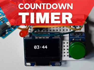
In this tutorial we are going to build a simple Countdown timer using an OLED Display & Arduino.
Items used in this project
Hardware components

Story
With pressing on a button the timer will start to count down and when it reaches zero an LED will turn ON.
By pressing again on the button the timer will restart.
Step 1: What You Will Need1 / 8
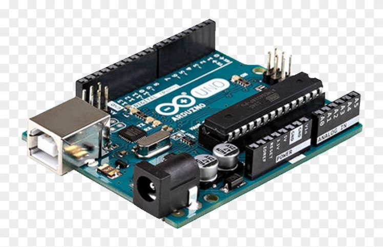
- Arduino UNO (or any other Arduino or ESP)
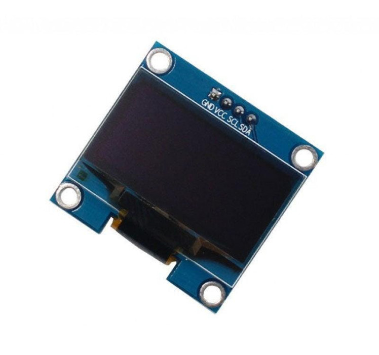
- OLED Display
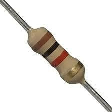
- Two 1K ohm resistors
- LED
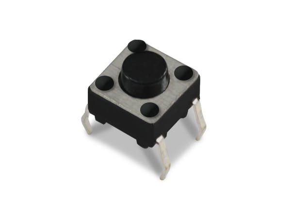
- Button
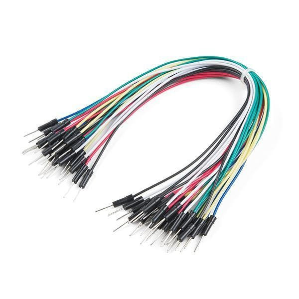
- Jumper wires
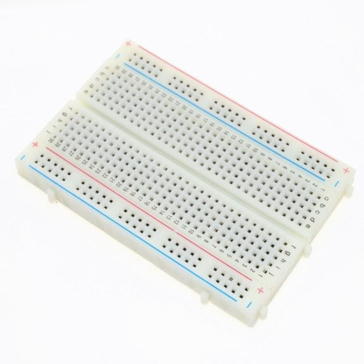
- Breadboard
- Visuino program: Download Visuino
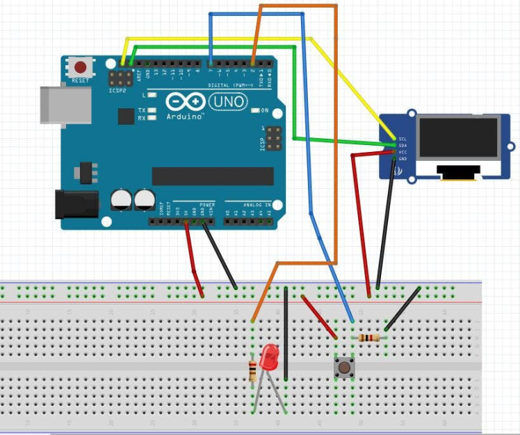
- Connect OLED Display pin [SCL] to Arduino pin [SCL]
- Connect OLED Display pin [SDA] to Arduino pin [SDA]
- Connect OLED Display pin [VCC] to Arduino pin [5v]
- Connect OLED Display pin [GND] to Arduino pin [GND]
- Connect Arduino Digital pin [7] to breadboard pin [GND] and to the Resistor1
- Connect other side of the resistor1 to the breadboard pin [GND]
- Connect Other pin of the button to the breadboard positive pin [5V]
- Connect Arduino pin [5V] to breadboard positive pin [Red line]
- Connect Arduino pin [GND] to breadboard negative pin [Black line]
- Connect Arduino Digital pin [2] to the Resistor2
- Connect other side of the resistor2 to the LED positive pin
- Connect LED negative pin to breadboard pin [GND]
1 / 2
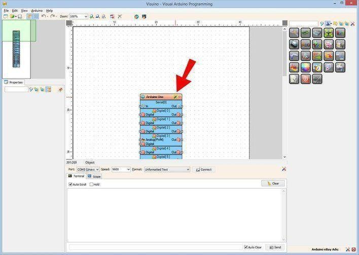
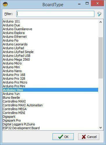
Start Visuino as shown in the first picture Click on the "Tools" button on the Arduino component (Picture 1) in Visuino When the dialog appears, select "Arduino UNO" as shown on Picture 2
Step 4: In Visuino Add Components1 / 12
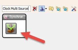

- Add "Clock Multi Source" component
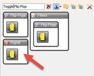
- Add "Toggle(T) Flip-Flop" component
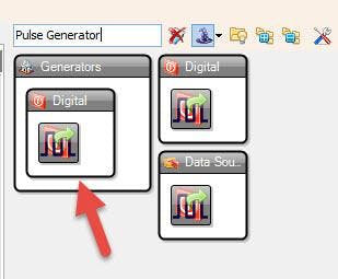
- Add "Pulse Generator" component
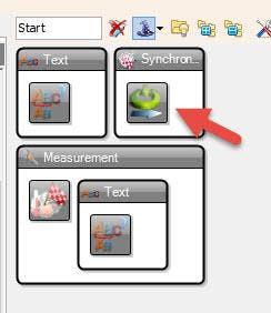
- Add "Start" component
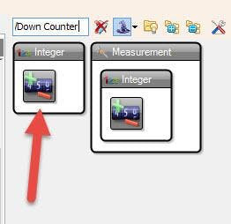
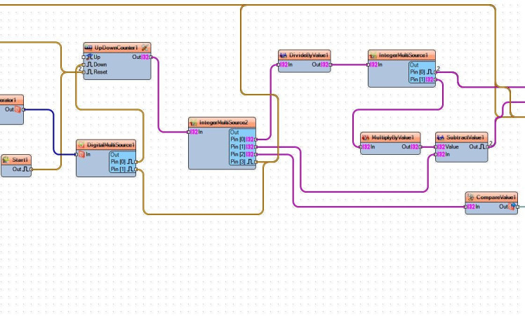
- Add "Up/Down Counter" component
- Add "Digital Multi Source" component
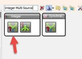
- Add 2X "Integer Multi Source" component
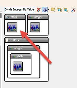
- Add "Divide Integer By Value" component
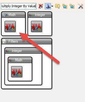
- Add "Multiply Integer By Value" component
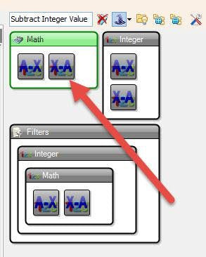
- Add "Subtract Integer Value" component
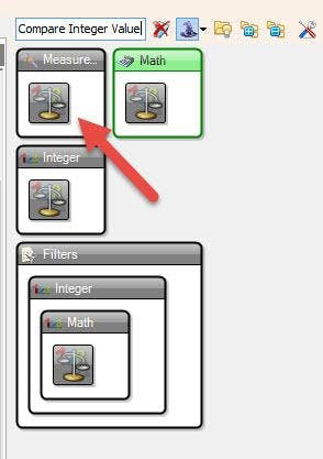
- Add "Compare Integer Value" component
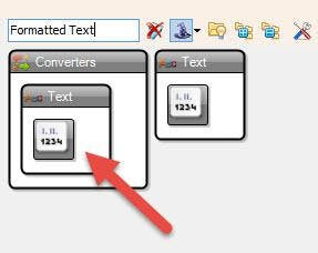
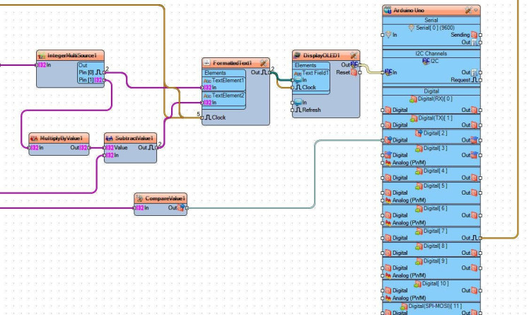
- Add "Formatted Text" component
- Add "OLED I2C" component
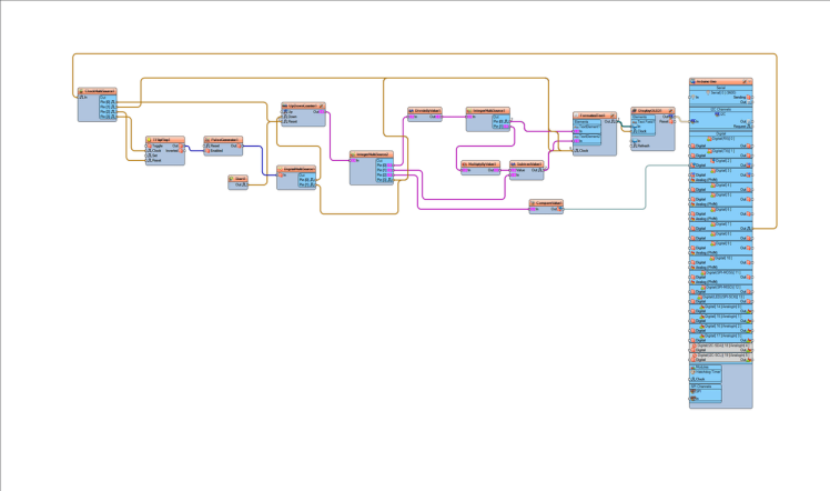
1 / 13
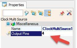
- Select "ClockMultiSource1" and in the properties window set "Output Pins" to 4
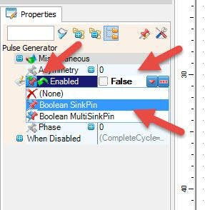
- Select "PulseGenerator1" and in the properties window set "Enabled" to False, and click on the pin icon and select "Boolean SinkPin"
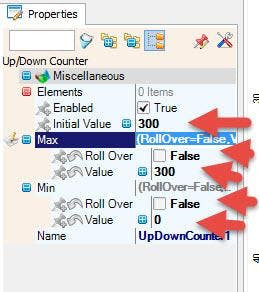
- Select "UpDownCounter1" and in the properties window set "Initial Value" to desired time in seconds we are going to use 300 seconds, also set Max > Value to 300 and "Roll Over" to Falseand set Min >Value to 0 and "Roll Over" to False
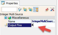
- Select "IntegerMultiSource2" and in the properties window set "Output Pins" to 4
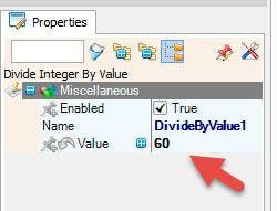
- Select "DivideByValue1" and in the properties window set "Value" to 60
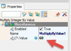
- Select "MultiplyByValue1" and in the properties window set "Value" to 60
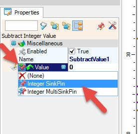
- Select "SubtractValue1" and in the properties window select "Value" and set it to 0 and click on the pin icon and select "Integer SinkPin"
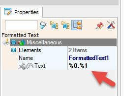
- Select "FormattedText1" and in the properties window set "Text" to %0:%1
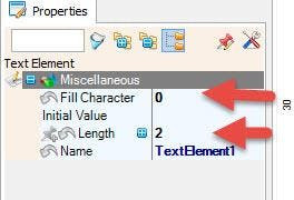
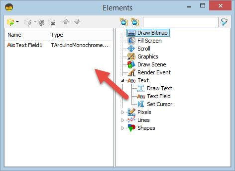
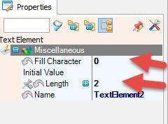
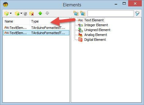
- Double click on the "FormattedText1" and in the "Elements" window drag 2X "Text Element" to the left side and for both set in the properties window "Fill Character" to 0 and "Length" to 2
- Close the "Elements" window
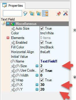
- Double click on the "DisplayOLED1" and in the "Elements" window drag "Text Field" to the left side and set in the properties window "Size" to 2, "X" to 30 and "Y" to 20
1 / 4
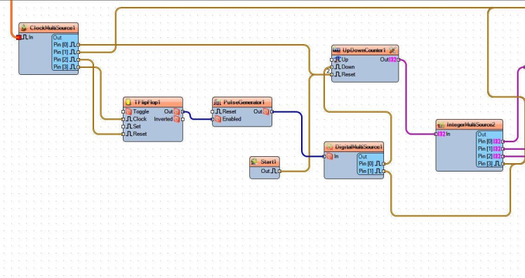
- Connect Arduino digital pin [7] to "ClockMultiSource1" pin [In]
- Connect "ClockMultiSource1" pin [0] to "UpDownCounter1" pin [Reset]
- Connect "ClockMultiSource1" pin [1] to "FormattedText1" pin [Clock]
- Connect "ClockMultiSource1" pin [2] to "TFlipFlop1" pin [Reset]
- Connect "ClockMultiSource1" pin [3] to "TFlipFlop1" pin [Clock]
- Connect "TFlipFlop1 pin [Out] to "PulseGenerator1" pin [Enabled]
- Connect "PulseGenerator1" pin [Out] to "DigitalMultiSource1" pin [In]
- Connect "Start1" pin [Out] to "UpDownCounter1" pin [Reset]
- Connect "DigitalMultiSource1" pin [0] to "UpDownCounter1" pin [Down]
- Connect "DigitalMultiSource1" pin [1] to "FormattedText1" pin [Clock]
- Connect "UpDownCounter1" pin [Out] to "IntegerMultiSource2" pin [In]
- Connect "IntegerMultiSource2" pin [0] "DivideByValue1" pin [In]
- Connect "IntegerMultiSource2" pin [1] "SubtractValue1" pin [In]
- Connect "IntegerMultiSource2" pin [2] "CompareValue1" pin [In]
- Connect "IntegerMultiSource2" pin [3] "FormattedText1" pin [Clock]
- Connect "DivideByValue1" pin [Out] to "IntegerMultiSource1" pin [In]
- Connect "IntegerMultiSource1" pin [0] to "FormattedText1" > "TextElement1" pin [In]
- Connect "IntegerMultiSource1" pin [0] to "FormattedText1" > "TextElement1" pin [Clock]
- Connect "IntegerMultiSource1" pin [1] to "MultiplyByValue1" pin [In]
- Connect "MultiplyByValue1" pin [Out] to "SubtractValue1" pin [Value]
- Connect "SubtractValue1" pin [Clock] to "FormattedText1" > "TextElement2" pin [In]
- Connect "SubtractValue1" pin [Clock] to "FormattedText1" pin [Clock]
- Connect "FormattedText1" pin [Out] to "DisplayOLED1" > "Text Field1" pin [In]
- Connect "FormattedText1" pin [Out] to "DisplayOLED1" > "Text Field1" pin [Clock]
- Connect "CompareValue1" to Arduino board Diital pin [2]
- Connect "DisplayOLED1" I2C pin [Out] to Arduino board I2C pin [In]
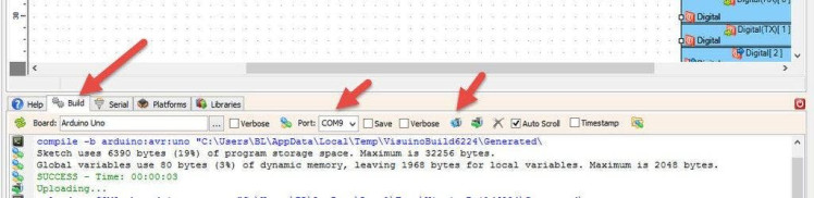
In Visuino, at the bottom click on the "Build" Tab, make sure the correct port is selected, then click on the "Compile/Build and Upload" button.
Step 8: PlayIf you power the Arduino module, The OLED Display will show the countdown time, if you press the button, a countdown will start and if you press it a gain the countdown will restart.
Congratulations! You have completed your project with Visuino. Also attached is the Visuino project, that I created for this tutorial, you can download it and open it in Visuino: https://www.visuino.eu
Schematics, diagrams and documents
Code
Credits
Related products


Leave your feedback...