
Oled Battery Level Indicator Using Arduino

About the project
In this Tutorial we are going to make a Battery Level Indicator using OLED Display.
Project info
Difficulty: Easy
Estimated time: 1 hour
License: GNU General Public License, version 3 or later (GPL3+)
Items used in this project
Hardware components

Story
This approach can be used to display anything that requires a level indication such as batteries, water level, etc.
For the demonstration we are going to simulate the signal with a potentiometer connected to Analog pin to get us the input voltage from 0V to 5V.
Step 1: What You Will Need1 / 6
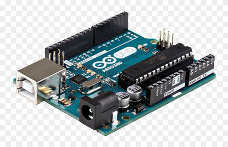
- Arduino UNO (or any other Arduino or ESP)
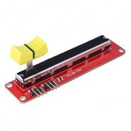
- Potentiometer module (If you dont have a Potentiometer you can connect directly Arduino pin 5V to A0 or 3.3V pin to A0, to see how it works)
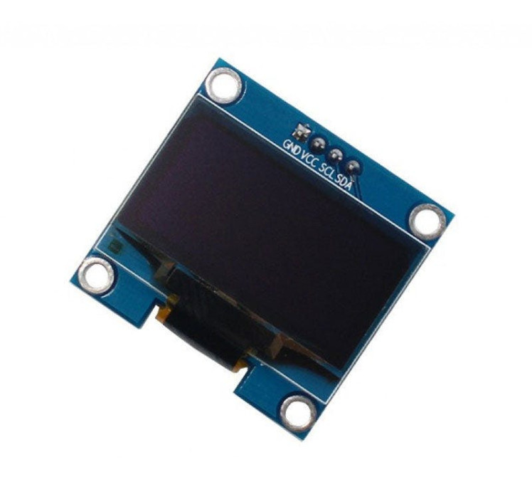
- OLED Display
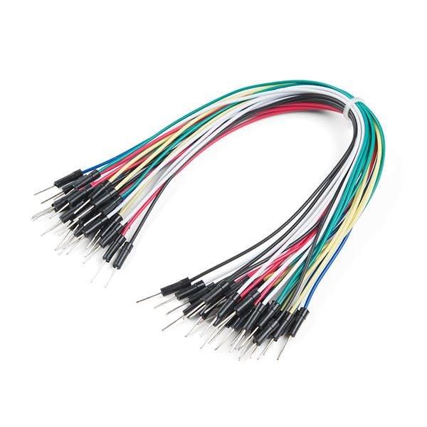
- Jumper wires
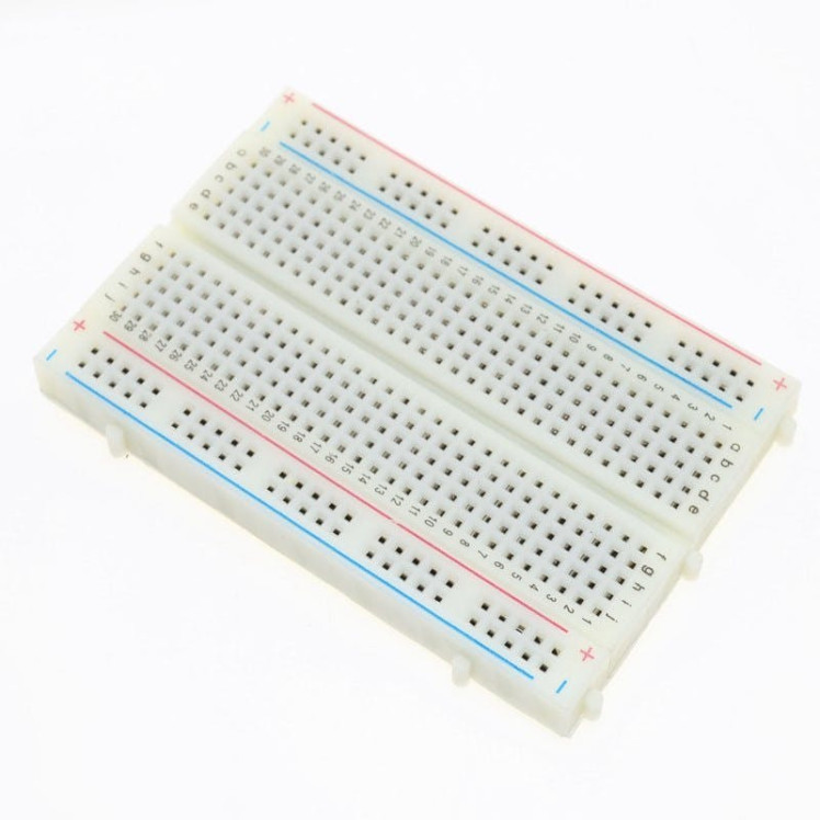
- Breadboard
- Visuino program: Download Visuino
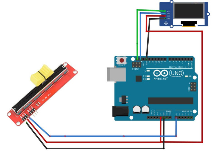
- Connect potentiometer pin [DTA] to arduino analog pin [A0]
- Connect potentiometer pin [VCC] to arduino pin [5V]
- Connect potentiometer pin [GND] to arduino pin [GND]
- Connect OLED pin [VCC]to arduino pin [5V]
- Connect OLED pin [GND]to arduino pin [GND]
- Connect OLED pin [SCL]to arduino pin [SCL]
- Connect OLED pin [SDA]to arduino pin [SDA]
1 / 2
The Visuino: https://www.visuino.eu also needs to be installed. Download Free version or register for a Free Trial.
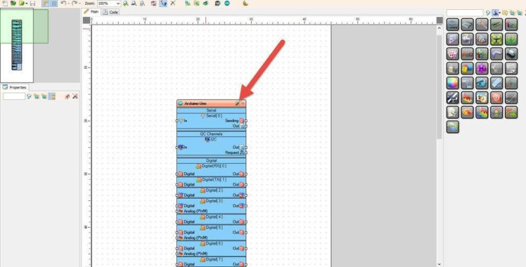
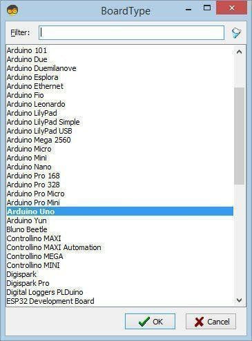
Start Visuino as shown in the first picture Click on the "Tools" button on the Arduino component (Picture 1) in Visuino When the dialog appears, select "Arduino UNO" as shown on Picture 2
Step 4: In Visuino Add & Set Components1 / 13
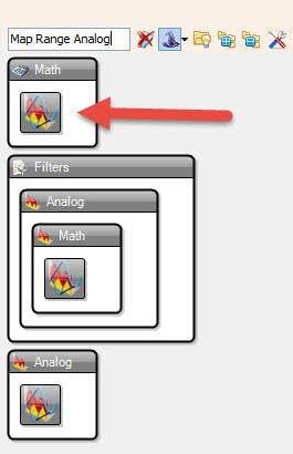


- Add "Map Range Analog" component
This component will adjust/convert our input to the desired level.
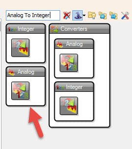
- Add "Analog To Integer"
This component will change our Analog number to Integer that is needed for the OLED
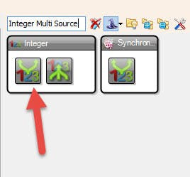
- Add "Integer Multi Source" component
This component will output our integer number on multiple pins.
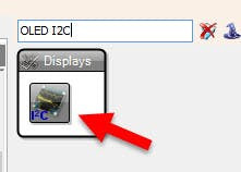
- Add "OLED I2C" component
- Select "MapRange1" and in the properties window set:
- Input Range > Max to 1
This is because our Analog 0 pin can give us maximum of 1
- Input Range > Min to 0
- Output Range > Max to 80
This is because our Battery Indicator Rectangle maximum width will be 80
- Output Range > Min to 0
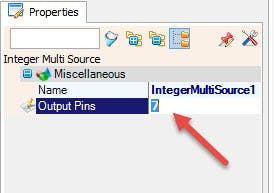
- Select "IntegerMultiSource1" and in the properties window set "Output Pins" to 8Good thing about "Integer Multi Source" component is that it triggers pins in order so it will first delete screen by triggering "Fill Screen" then it will trigger "Draw Rectangle1", etc.
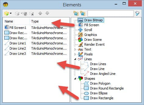
- Double click on the "DisplayOLED1" and in the "Elements Window":
- Drag "Fill Screen" to the Left Side <
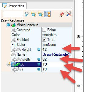
- Drag "Draw Rectangle" to the Left side < and in the properties window:set "Height" to 42, "Width" to "82", "X" to 19, "Y" to 19
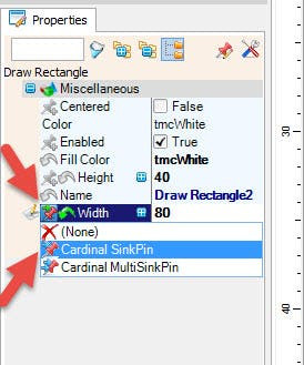
- Drag another "Draw Rectangle" to the Left side and in the properties window:set "Height" to 40, "Width" to "80", "X" to 20, "Y" to 20set "Fill Color" to tmcWhiteSelect "Width" and click on the Pin Icon button and select "Cardinal SinkPin"
Now Optional if you want your Battery Level Indicator to look more like a battery we can add some stripes to do this:
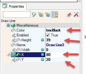
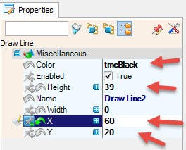
- Add 3X "Draw Line" to the left side and set in the properties window for all of them "Color" to "tmcBlack"
- For "Draw Line1" in the properties window set "Height" to 39 "X" to 40 and "Y" to 20
- For "Draw Line2" in the properties window set "Height" to 39 "X" to 60 and "Y" to 20
- For "Draw Line3" in the properties window set "Height" to 39 "X" to 80 and "Y" to 20
And Close the "Elements Window"
Step 5: In Visuino Connect Components1 / 2
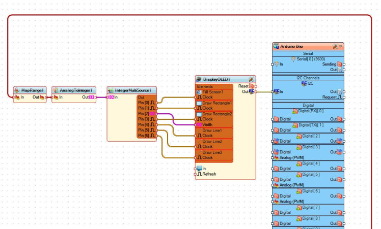
- Connect "Arduino" board Analog Pin [0] to "MapRange1" pin [In]
- Connect "MapRange1" Pin [Out] to "AnalogToInteger1" Pin [In]
- Connect "AnalogToInteger1" Pin [Out] to "IntegerMultiSource1" Pin [In]
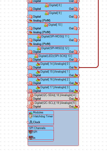
- Connect "IntegerMultiSource1" Pin [0] to "DisplayOLED1" > "Fill Screen1" Pin [Clock]
- Connect "IntegerMultiSource1" Pin [1] to "DisplayOLED1" > "Draw Rectangle1" Pin [Clock]
- Connect "IntegerMultiSource1" Pin [2] to "DisplayOLED1" > "Draw Rectangle2" Pin [Width]
- Connect "IntegerMultiSource1" Pin [3] to "DisplayOLED1" > "Draw Rectangle2" Pin [Clock]
- Connect "IntegerMultiSource1" Pin [4] to "DisplayOLED1" > "Draw Line1" Pin [Clock]
- Connect "IntegerMultiSource1" Pin [5] to "DisplayOLED1" > "Draw Line2" Pin [Clock]
- Connect "IntegerMultiSource1" Pin [6] to "DisplayOLED1" > "Draw Line3" Pin [Clock]
- Connect "DisplayOLED1" Pin I2C [Out] to Arduino Pin I2C [In]
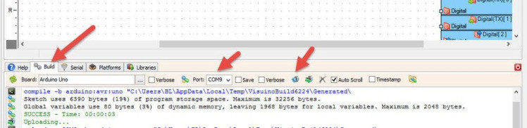
In Visuino, at the bottom click on the "Build" Tab, make sure the correct port is selected, then click on the "Compile/Build and Upload" button.
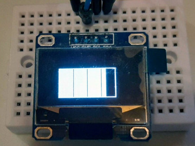
Step 7: PlayIf you power the Arduino module, the OLED Display will start to show the Value from the Analog Pin as a Battery Level, If you connected a potentiometer to the Analog Pin then you can change the position and see how it will affect the Indicator on the OLED Display.
Congratulations! You have completed your project with Visuino. Also attached is the Visuino project, that I created for this Tutorial, you can download it and open it in Visuino: https://www.visuino.eu
Schematics, diagrams and documents
Code
Credits
Related products


Leave your feedback...