
Motion Detection Automatic Light On/off With Hexabitz

Made by Aula_Jazmati / Games & Gaming / Holidays / Home Automation / Kids & Family / Lights
About the project
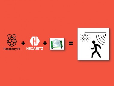
Automating home stuff is fun. In this tutorial we are using PIR sensor to detect motion and turn ON bulb using Raspberry Pi and Hexabitz.
Project info
Difficulty: Moderate
Platforms: Adafruit, Raspberry Pi, STM32 Nucleo, STMicroelectronics
Estimated time: 1 hour
License: MIT license (MIT)
Items used in this project
Hardware components

Story
Automating home stuff is fun. In this tutorial we are using PIR sensor to detect motion and turn ON bulb using Raspberry Pi and Hexabitz. And it will remain ON for 1 minute if no motion detected. Obviously you can increase or decrease this time.
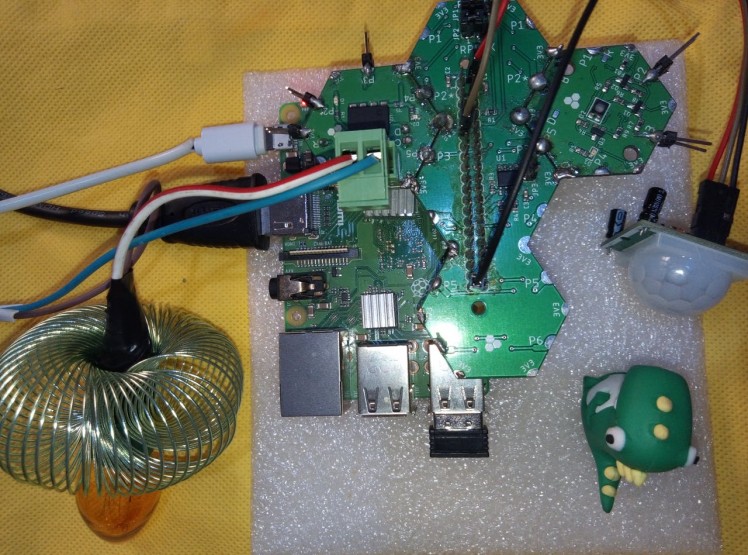
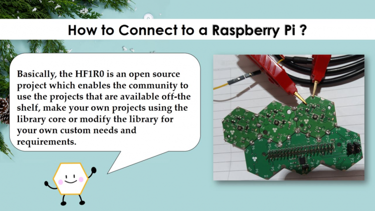
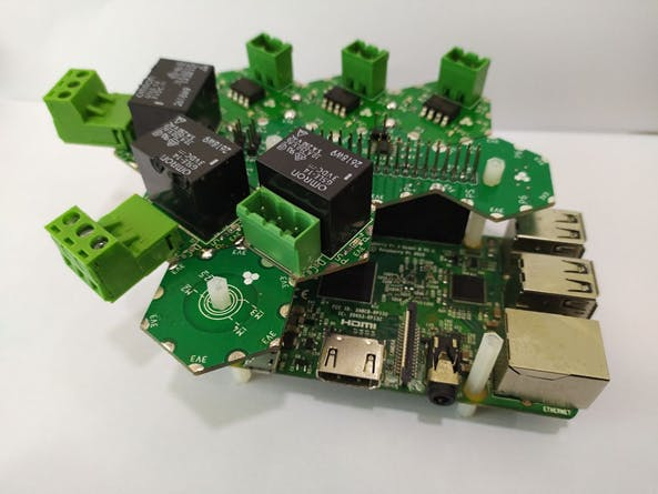
How I build it ?️ Step 1: Hardware Design and Implementation1-Raspberry Pi Interface (HF1R0x)
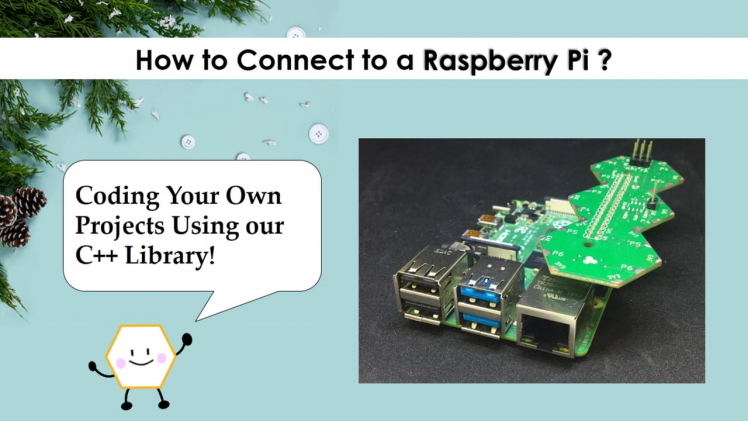
HF1R0x is Hexabitz Raspberry Pi interface module. It interfaces seamlessly to Raspberry Pi 3B/3B+/4B single-board computers and enables you to connect and control your favorite Hexabitz modules from the Raspberry Pi operating system and build your own Raspberry Pi Hat.
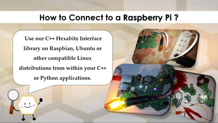
You can use C++ Hexabitz Interface library on Raspbian, Ubuntu or other compatible Linux distributions from within your C++ or Python applications.
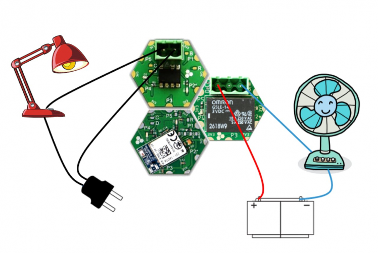
How to Connect to a Raspberry Pi Single-Board Computer?“Part 1”2- Solid State Relay (H0FR6x)
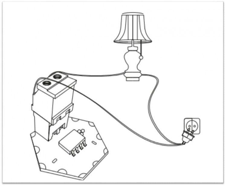
H0FR6x is a compact solid state relay (SSR) module capable of driving AC loads up to 600V and 1.2A. It is based on Panasonic AQH3213A SSR and STM32F0 MCU. You can use as a stand-alone smart AC relay and easily control AC loads (lamps, fans, power outlets, etc.).
Solid State Relay (H0FR6x)3- PIR Motion Sensor
PIR sensors allow you to sense motion, almost always used to detect whether a human has moved in or out of the sensors range. They are small, inexpensive, low-power, easy to use and don't wear out. For that reason they are commonly found in appliances and gadgets used in homes or businesses. They are often referred to as PIR, "Passive Infrared", "Pyroelectric", or "IR motion" sensors.
How PIRs Work

How PIRs Work
The IR sensor itself is housed in a hermetically sealed metal can to improve noise/temperature/humidity immunity. There is a window made of IR-transmissive material (typically coated silicon since that is very easy to come by) that protects the sensing element. Behind the window are the two balanced sensors.
The PIR Sensor

The PIR Sensor
Fresnel lenses

Fresnel lenses
The Fresnel lens condenses light, providing a larger range of IR to the sensor.
1 / 2 • Image from BHlens.com

Image from BHlens.com

Image from Cypress appnote 2105
This is a simple to use motion sensor. Power it up and wait 1-2 seconds for the sensor to get a snapshot of the still room. If anything moves after that period, the 'alarm' pin will go low.
1 / 2 • PIR Motion Sensor

PIR Motion Sensor

PIR sensor
There is two trim port on PIR sensor, One is for Sensitivity and second is for Time trigger (Delay time) port. You can choose sensitivity according to your needs and you can also set delay time by moving trim port knob to the right or left. Left side is for low time that is 0.3 second and Right side is for HIGH, its time around 5 minutes. You can use manufacturer tutorial for accurate information.
Output: Digital pulse high (3V) when triggered (motion detected) digital low when idle (no motion detected). Pulse lengths are determined by resistors and capacitors on the PCB and differ from sensor to sensor.
Sensitivity range: up to 20 feet (6 meters) 110° x 70° detection range
Power supply: 5V-12V input voltage for most modules (they have a 3.3V regulator), but 5V is ideal in case the regulator has different specs
Notes:
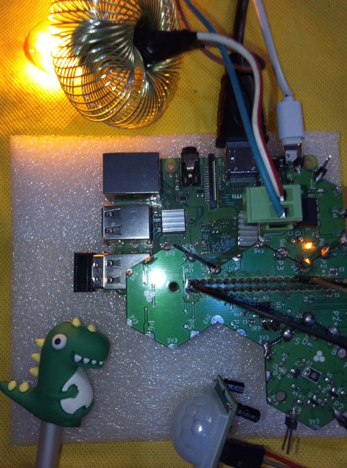
- Plan the array and assemble the hardware
- Connect the H0FR6 Module to HF1R0 module.
- Be sure to download the firmware on the module before soldering.
- Make sure to connect Hexabitz relay module at the right spot or left spot. In this project, I have Jumper JP1 and JP2 at position 1 & 2 and the module is soldered as shown in the picture below:
- Install Raspberry Pi OS using Raspberry Pi Imager

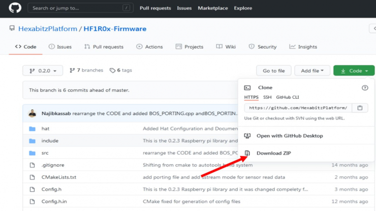
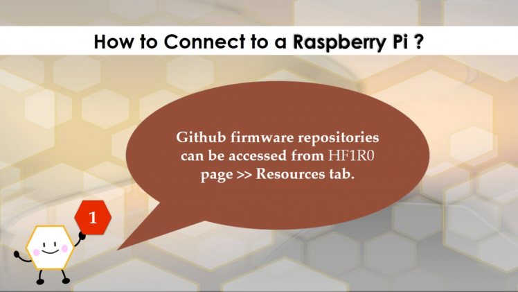
- Github firmware repositories can be accessed from HF1R0 page >> Resources tab.
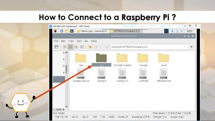
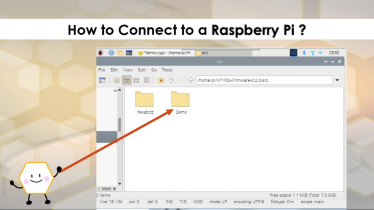
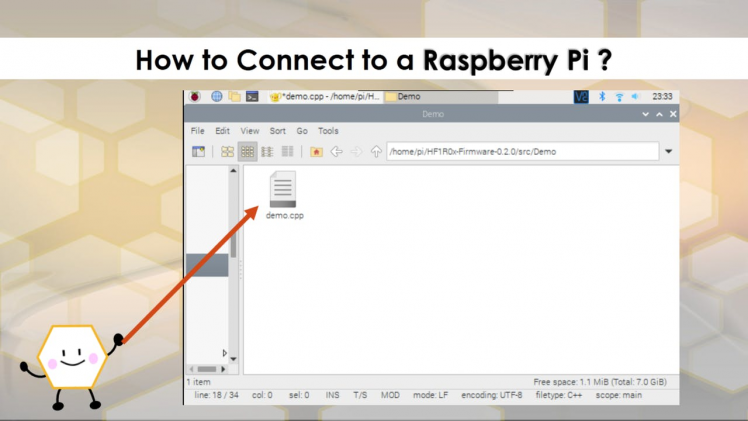
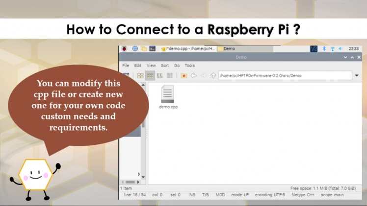
- Your application code should be mainly written in Demo folder for easy portability to future revisions.
- You can modify this cpp file or create new one for your own code custom needs and requirements.
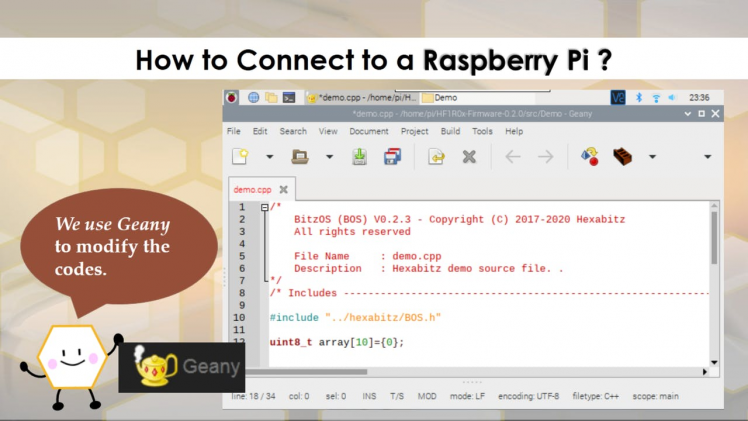
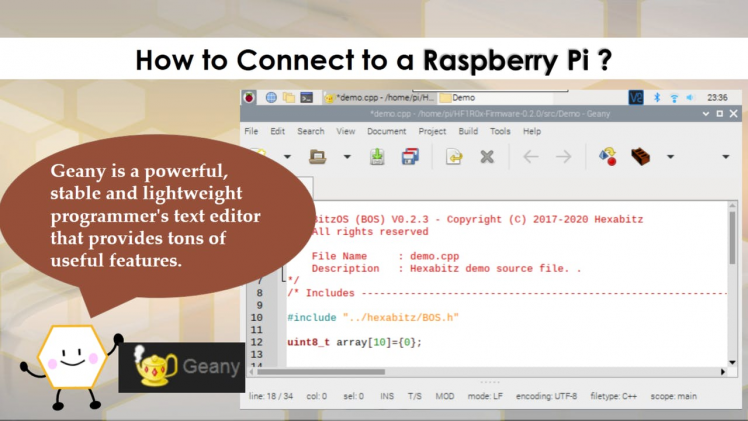
- You can use a Geany to modify the codes. Geany is a powerful, stable and lightweight programmer's text editor that provides tons of useful features.
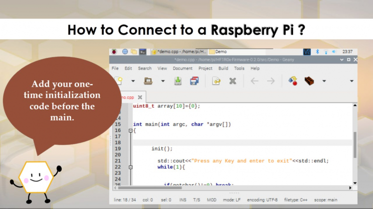
- Add your one-time initialization code before the main.
- Add your Messages inside the main and Initialize the input (PIR sensor).
- WiringPi is developed directly on a Raspberry Pi running 32-bit Raspbian.
How to setup Hexabitz Raspberry Pi Interface Module Firmware for the first time?
1 / 6

1 / 3

1 / 4

1 / 5
sudo apt-get update
sudo apt-get upgrade
sudo apt-get install build-essential
sudo apt-get install cmake
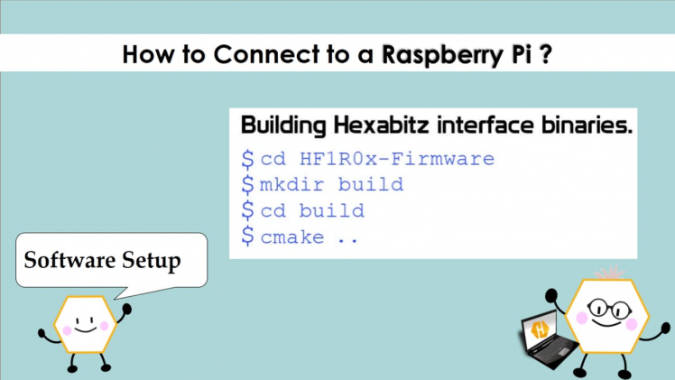
cd ~
git clone https://github.com/HexabitzPlatform/HF1R0x-Firmware.git
cd HF1R0x-Firmware
git checkout master
rm -rf build
mkdir build
cd build
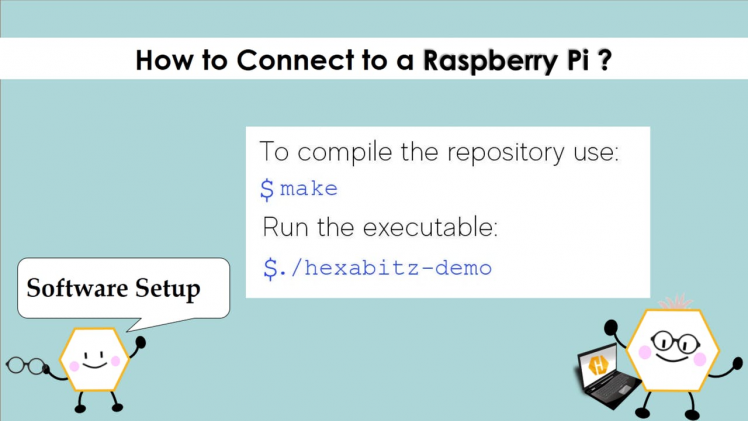
cmake ..How to compile the repository?
makeHow to run the executable?
./hexabitz-demoCode Explanation ?️ ? ?
Define PIR sensor pin number and set PIR sensor as an Input.
1 / 2 • RPi GPIO

RPi GPIO
If PIR sensor detect motion, it will give HIGH signal, if it is HIGH, Bulb will turn ON (SendMessageToModule ? ). It will remaining on until the delay time is set on PIR sensor.
H0FR6 Messages

H0FR6 Messages
1 / 2 • Send Message To Relay Module

Send Message To Relay Module

How to run the executable?
Step 3: Test the System ??
You can connect many H0FR6 modules together and combine with H0FR1 to drive DC loads as well ?✨
1 / 3
Schematics, diagrams and documents
Code
Credits
Related products


Leave your feedback...