

Midi Sequencer Using Thermal Camera

Made by Dillon1337 / Art / Displays / Environmental Sensing / Sensors / Virtual Reality
About the project
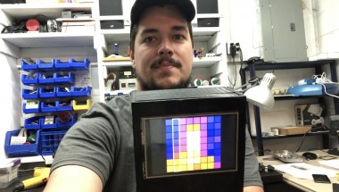
The Giant Board linux computer takes an 8x8 thermal image and displays it on the TFT while also assigning a musical note to each temperature. It plays a song corresponding to the temperature of the object.
Project info
Difficulty: Moderate
Platforms: Adafruit, Microchip
Estimated time: 3 days
License: Creative Commons Attribution CC BY version 4.0 or later (CC BY 4+)
Items used in this project
Hardware components

Story
Introduction
This project uses the Adafruit AMG8833 IR Thermal Camera FeatherWing to make an 8x8 grid array of temperatures which are shown as colors on a TFT FeatherWing. The temperatures are also converted to MIDI notes in Python and send to the Adafruit Music Maker FeatherWing to play as a Sequencer. All of this is controlled via a Giant Board, which is a very small Linux computer.
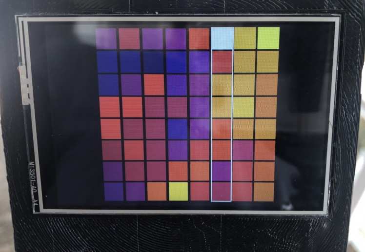
The combination of the thermal camera and display is a very basic form of a thermographic camera. I use a color scale where a range of Black → Purple → Pink → Orange → Yellow → White corresponds to Cold → Hot temperatures. I scale each image capture so the coldest point is black and the hottest point is white and the rest of the points are colored in between appropriately. Then I add some sound.
A sequencer steps through notes and plays them. Here's a fun application to try it out yourself and is the inspiration for the music generation. My application plays each column of 8 pixels simultaneously. The music maker can play 128 different notes, so I divided the notes by the pixels so that each pixel has 8 possible values. So we take a pixel (which is a single temperature) and see where that temperature is inside the range from coldest to hottest points. For example, if the coldest point was 20 degrees, and the hottest point was 40 degrees, a point that was 30 degrees (midway) would be assigned a value of 4 (out of the possible 8 -- again midway). Each pixel in the column has a base note. The bottom pixel has a base note of 0 (so it could be anywhere from 0-7), then the second pixel up starts at 8 (could be from 8-15), and so on. So if the previously described 30-degree point was on the second pixel it would be assigned a note of 8 + 4, or 12. Each pixel in the column gets a note and they are all played simultaneously for a quarter note, then the next column's notes are played.
This combination of hardware and software essentially generates music from something that can't be seen in the environment. I think it's really interesting to extract this data and provide a new way to experience it. Check out the following videos for the hardware details and some music generated by things around me.
Video
Hardware
The hardware consists of the Giant Board as the brains and a couple of Adafruit FeatherWings for the additional functions. I'll explain each one in detail and the modifications needed to make them all compatible.
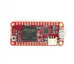
Giant Board
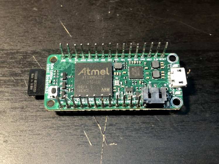
First off, we have the Giant Board. It needs a micro SD card flashed with the image to boot into Linux. I'll explain the software portion of the project later. I installed extra-long headers onto the board so pins stick out from each side and this board can be sandwiched between the display and the FeatherWing Tripler.
Display
Next is the display which is an Adafruit TFT FeatherWing - 3.5" 480x320 Touchscreen for Feathers. I'm not using the touchscreen portion of it in this project. This piece doesn't require any hardware modifications - just plug and play.
Thermal Camera
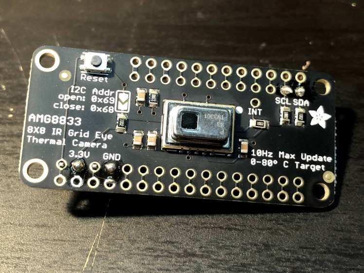
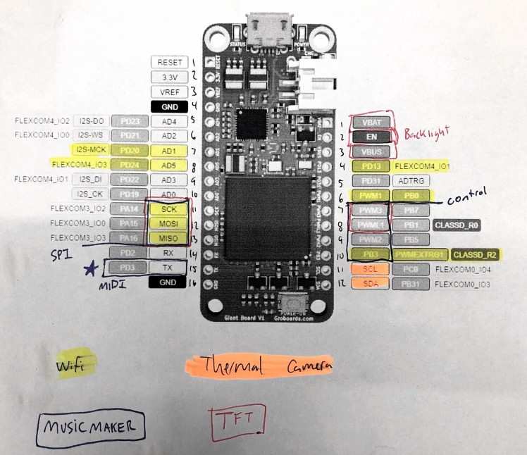
The thermal camera is an Adafruit AMG8833 IR Thermal Camera FeatherWing. It has an 8x8 array of IR thermal sensors which will measure temperatures ranging from 0°C to 80°C (32°F to 176°F). This device only needs power and I2C so I only connected the 3.3V, GND, SCL, and SDA pins.
Music Maker
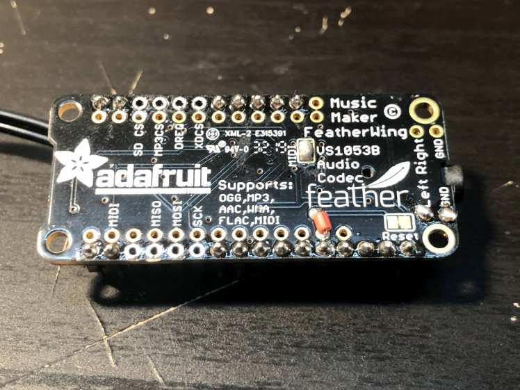
The sound is generated from an Adafruit Music Maker FeatherWing. This board has a ton of features but I'm going to be using it in MIDI mode (here's a great introduction to MIDI if you want to learn more). This way I have direct control of the sounds which are generated. This also helps to keep it simple because I don't need to connect the SPI or control pins which are used by the TFT display already. If you check out where I soldered the headers, I specifically did not install headers in those locations so it did not interfere with the display communications. The pins really only need to be installed for the power pins, MIDI, and reset.
This board required the most hardware modifications. First, you'll need to short the MIDI jumper pads with solder. The MIDI communication happens over UART and it just so happens that the Giant Board's default serial terminal uses these same pins. I didn't want to disable the UART because it was useful for debugging the Linux startup, so I modified this FeatherWing so the Giant Board could reset the Music Maker without resetting the rest of the boards. To do this, I cut the trace on the Reset jumper pads and added a wire (seen in red above). This wire connects the Music Maker's rst signal to the Giant Board's AD4 pin. What happens is that the Music Maker sees the Giant Board's startup text on the MIDI pin (which is just jumbled junk to it because it's the wrong baud rate), so I reset the Music Maker and then control it over that same UART pin but at the correct 31250 baud rate.
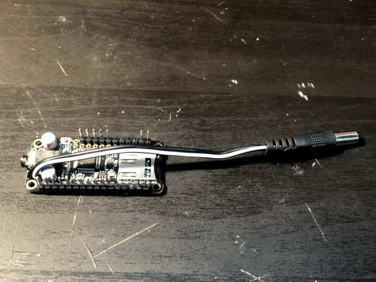
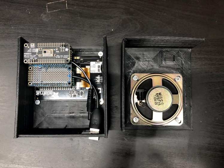
During testing, I used a normal speaker connected to the 3.5mm jack, but I didn't have room to connect it this way inside the enclosure. I found that a single speaker was loud enough for my application so I directly soldered it to the Left channel and GND pins. I used a barrel jack connector because it was the only 2 pin connector I had that fit in my enclosure. This made it so I could easily separate the halves of my enclosure for debugging.
Connections
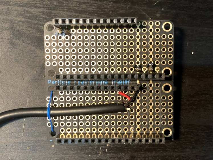
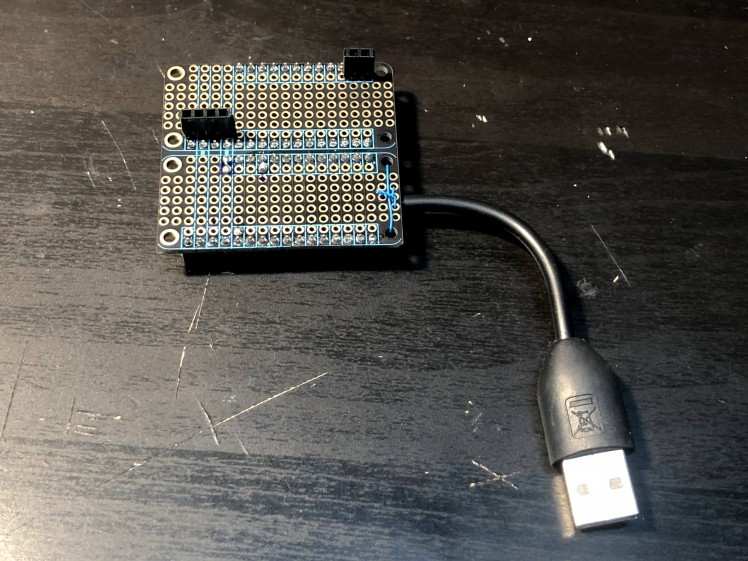
I used a modified FeatherWing Tripler to connect all of the FeatherWings (but I really only needed a FeatherWing Doubler). This board connects each of the FeatherWing connections for you so you only need to think about where to put the headers. I put two full connection sets on one side for the Giant Board and the Music Maker and the other side just has a few headers for the Thermal Camera. I also added a chopped-up USB cable to the VBUS and GND pins so I could power everything from a USB battery bank. With everything connected, I'm only drawing about 250mA so the USB battery bank is a perfect choice.
Software
The Giant Board runs Linux which makes it very powerful but also has a steep learning curve. I had a general understanding of Linux before, but this project taught me so many more details.
The first step is to boot into Linux from the burned SD card as explained here. I created a few scripts to make startup easier. After cloning my GitHub repository, use this script to copy my files to the Giant Board. On the Giant Board, running first-boot.sh sets up the system according to the Getting Started Guide and then resets. After that, run eth-setup.sh to set up the Giant Board as a shared connection so it has internet access.
Next, we're going to set up overlays so we can control the display and I2C lines. Modify the uEnv.txt as shown here. The overlay for the 3.5" display should be copied over. The 3.5" display was not supported at first, but Groguard helped me made the modifications to get it working. My overlay is also modified so that the display is rotated 270° which makes it face the right way up in my stackup of boards.
The last step before running the application is to install the dependencies for my code so we can draw to the screen using pygame and use a CircuitPython driver to communicate to the thermal camera. I use Pygame to draw directly to the frame buffer which seemed to be the only option for a custom GUI on such a constrained device.
Now we can run my application which is the display.py and midi.py Python files. I'll give a basic overview of how everything works starting with the main display.py file. First up, we load the necessary libraries and set up communications to the devices. Adafruit wrote an awesome library for the thermal camera so it only takes a couple of lines to grab the data from the 8x8 thermal measurement. I also set up the display which requires a few settings to make it an application GUI.
Instead of having a constantly updating display based on what the thermal camera sees, I take one capture from and then do all of the drawing and sound generation based on that. I take the full 8x8 pixel array and calculate the minimum and maximum temperatures to create an accurate spread of colors. I'm using a modified color palette based on FLIR's colors as described here. Then I draw all of the pixels in the calculated color to the screen. As I cycle through the columns and play the notes, I also draw a white rectangle around the column I'm on so that it's obvious what is being played. To remove the white rectangle, I draw over it in black and move to the next white rectangle. This way I don't have to redraw the entire 8x8 array for each note change.
I explained earlier how the notes are determined, but not how they are played. The midi.py file handles all communications with the Music Maker chip. As described in the hardware section, I start by resetting the music maker and then setting up the UART to the Music Maker at 31250 baud. Next, I do some initialization of the chip which includes setting the channel to play notes, setting it to max volume, and setting the instrument (I chose Ocarina, but there are about 80 different instruments inside this chip). Now I can play each note in the column by sending the Note On command for each one and then I turn them all off after a quarter note pause. Then it moves to the next column and repeats. I don't know anything about music, but I do understand hardware and software so I'm so amazed a basic UART (MIDI) command can generate sound.
The code is pretty simple. but opens up other ways of bringing this sensor data in and "visualizing" it as light and sound. I'd like someone that is more musically-inclined than me to play around with this framework and share their results.
As a final note for the software section, I use this rc.local to autorun my code when Linux boots so it doesn't require any user interaction to get everything started.
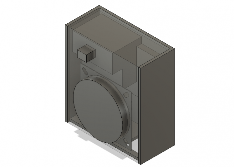
Enclosure
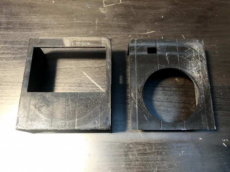
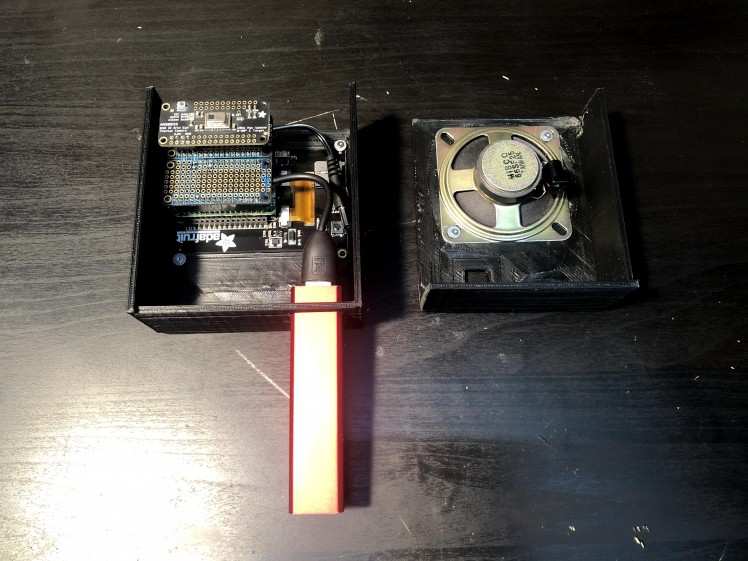
I've had my 3D printer for years and I mainly use it to make custom enclosures for my electronics projects, but this time I tried something new. I used Fusion 360 to model and layout my components and then design an enclosure around them. Typically I only model the enclosure and that's it. I should've spent some more time learning how components work in Fusion, but I muddled my way through it. I modeled the electronics as one block which included the display on one side and the thermal camera on the other. The speaker was another piece. Then I moved them in 3D space and built the enclosure around it.
Unfortunately, I missed that the speaker and electronics were overlapping when I printed the first revision and had to modify it a little and print everything again. But this also gave me a chance to add some more features. I added a hole in the side for the Giant Board's USB port so I could still develop my application when everything is assembled. My second set warped while it was being printed, but only one side was really bad so I just re-printed one of the pieces and I had a full enclosure. I used small screws from a broken hard drive to attach the display and speaker and the two printed pieces are held together by friction. The USB battery pack made the perfect handle so that piece is dual function. Overall, it's not very complex, but it gets the job done.
Conclusion
It's been fun hearing what things around me sound like. I designed this as a silly art project, but I think it could have uses outside of that. It could be pointed at a hot grill or stovetop and a person with visual impairment could use the sounds to know the temperature of the grill. There may be other important uses outside of that too. I hope in sharing this project, others will be inspired to build their own and modify the software to have fun or solve their challenges.
I want to thank the designer of this board, Groguard, for the awesome hardware and incredible support they've given me during this project. I made a few posts on the forum and Groguard happily answered and even built a few custom Linux images just for me. This was a fairly complex Linux project, and I didn't even know about device tree overlays or framebuffers, or USB gadgets, or how to build a Linux kernel before starting this, so I'm glad I have that knowledge now to use at my day job.
If you have any questions about the project, please reach out to me on Twitter!
Schematics, diagrams and documents
CAD, enclosures and custom parts
Code
Credits
Related products


Leave your feedback...