
Making A Gesture Controller Glove Using Hall Effect Sensor
About the project
Hey guys, in this video, we will be making a compact circuit that can be fitted in a glove to control Robots using Gesture commands.
Items used in this project
Hardware components

Story
Hey guys, in this video, we will be making a compact circuit that can be fitted in a glove to control Robots using Gesture commands. It’s really cool to control a pick and place robot completely using hand gestures right? I have been making gesture controlled robot and controlling it using a flex sensor and accelerometer. Then I thought of replacing the flex sensor with a hall effect sensor. Why? Because we can easily fix it inside the glove and the switching can be done more efficiently. So let’s take a look at the circuit.
CircuitHere you will see a voltage input terminal, Vin gloves, where I can connect a 9-volt battery or a DC power adaptor. This voltage input is connected to a 7805 voltage regulator which will convert an unregulated DC voltage of 7 to 32 volt to 5 volt DC power supply. This 5 V is then connected to Arduino, HC12 Wireless module, Indicator LED as well as the accelerometer.
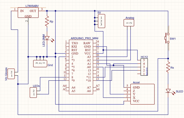
For this project, I decided to go with Arduino Pro Mini because of its small size. But of course, you can use any Arduino board for this project.
IO pins 8 and 9 are connected to two terminals where I was planning on connecting some 5 V LEDs. X and Y output of the accelerometer is connected to analog pins a0 and a1 of Arduino.
These are some headers that are connected to the analog pins of Arduino in this PCB. The reason why I added that is to connect 2 analog hall effect sensors. I will be using one of them to close and open the claw and the other to switch between control of the robot and control of the claw. And here is another switch with which can manually trigger a switching action.
Basically, that’s all I needed for this project. If you are planning on making it, make sure you try it out on a breadboard and once you get the output you can use it as such or create your own PCB.
1 / 2

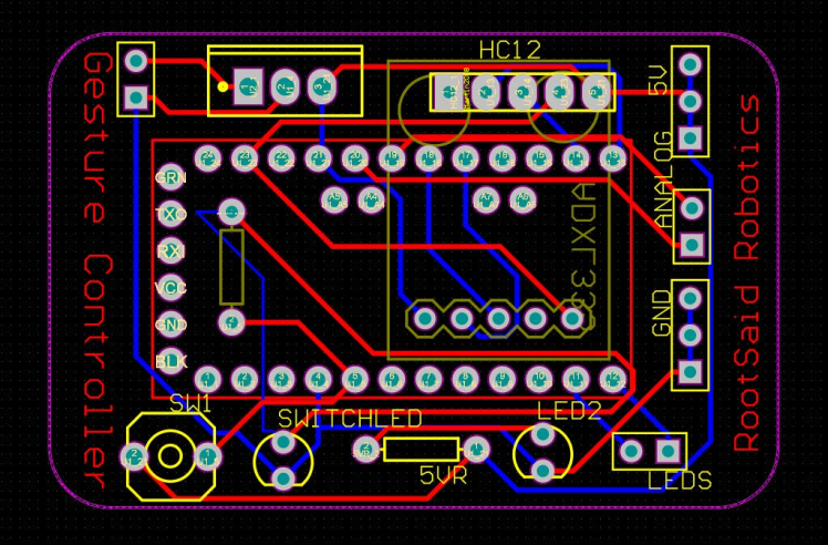
I personally like PCBs. PCBs are neat and help to get rid of all nasty wires hanging around. And it’s cool to make your own PCBs for your project right? Once the circuit was finished and tested, I designed a compact PCB using Altium, where I can fix all the components neatly. Here you can see routing is on both sides of the board which means it is a dual-layer PCB.
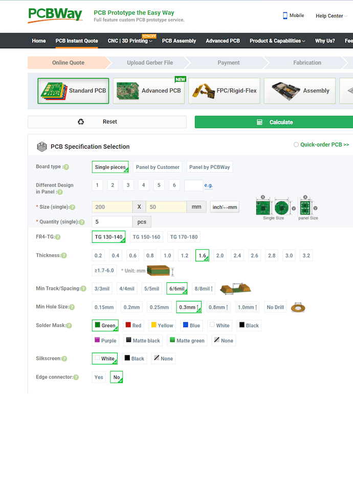
Getting PCBs DoneI ordered my PCB from PCBWay. PCBWay is a PCB manufacturer specializing in PCB prototyping, low-volume production, and neat and tidy PCB Assembly. To order your PCB from PCB way, Go to the PCBWay website and fill in the basic board details in the instant order form.

And in the next screen, you can completely customize your PCB. You can change the thickness, change the solder mask color as well as the silkscreen color, materials used, you can customize it in every way possible. Corresponding prices will be updated here in real-time. In PCBWay, you can even manufacture your PCBs with TG 150-160 for the same prices as that of TG 130-140 which means your PCB will be able to operate at high temperatures without any damage.
In the next screen, you should be able to upload your Gerber file and submit it for review. Once the review is completed, all that is left is to add to the cart, make the payment, and wait for your PCBs to arrive.
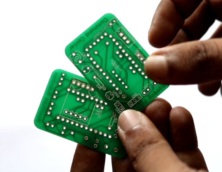
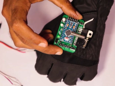
Once you get all the components and the PCB, it’s time for you to solder them together. Solder all the components onto the board and make sure to check the polarity of the components. After soldering the PCB looks like this. And this is it. This one is small and I think it will fit nicely on top of the glove.
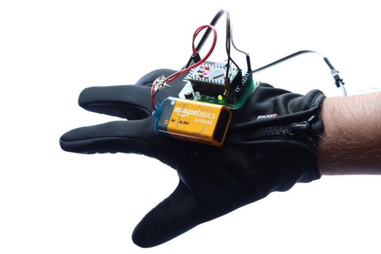

Here is the assembled board. On top, we have Arduino pro mini, a switch, a 7805 regulator, and some header pins where we can connect the hall effect sensors. Below we have the ADXL335 accelerometer which will sense the tilt. The output of the sensor is wired directly to the Arduino. And on top, here, we will connect the wireless module. For this project, I will be using an HC 12 wireless module which has a maximum range of 1Km Line of Sight.
This is the glove I will be using for this project. I will be fixing this board on top of this glove like this Here I will be using this linear hall effect sensor. This one is an A1302 linear hall effect sensor which will give an analog output when brought near a magnetic field. The first pin is VCC which is 5V, the second pin is ground and the third pin is Vout which is directly proportional to the magnetic field.
I have already soldered two of them with these jumper wires that I can easily connect with the header pin on the circuit board. These hall effect sensors will be fixed somewhere near the fingertip of the glove. And finally, I will be gluing a strong tiny magnet somewhere here.
This is how it works, when I fold or open my fingers, the distance between the magnet and the hall effect sensor changes, and the magnetic field surrounding the hall effect sensor changes which will alter the output voltage of the Hall effect sensor.
When My hands are open, the distance between the hall effect sensor and the magnet will be maximum and so the output of the hall effect sensor will be minimum. When I fold the finger, the hall effect sensor will be close to the magnet and so the output voltage increases.
With these hall effect sensors along with this circuit board that contains the accelerometer, I will be able to create a control glove that will be able to control things like these robots and robotic arms much better than my previous glove with the flex sensor.
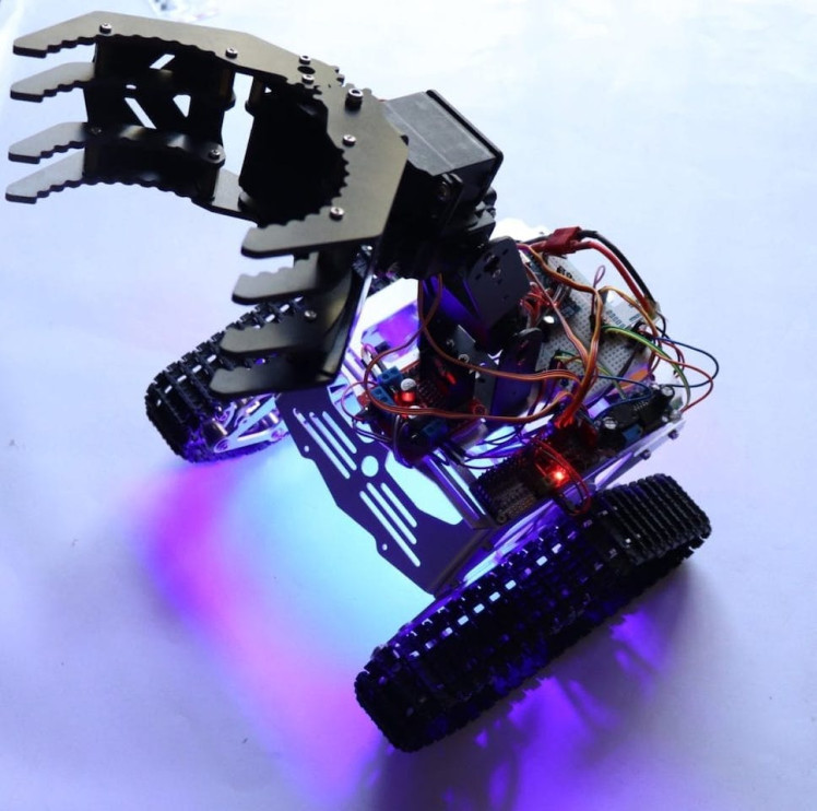
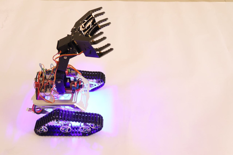
The RobotNow, we can work on the Robot. The robot body that I will be using, will be this tracked robot chassis. the best part of this robot chassis is that I can easily attach this robotic arm on top of it. In order to control this Robot, I will be using another Arduino board. This out in a boat will be connected to another HC12 Wireless module that will be receiving data from the remote controller.
1 / 2
If you’re not using the robotic arm then we don’t have to use a Servo motor driver. We can simply dry all the motors using a simple l293d motor driver IC. if we want to control Servo Motors of the robotic arm we should use an additional Servo motor driver.
CodingI will share the code of the remote controller as well as the Robot in the description down below.
In the remote controller part what we’re doing is we will be collecting the inputs from the accelerometer, the hall effect sensor as well as the switch and storing it in different variables. Once we have done that we will be converting them into a string of values separated by commas. Once we have constructed the string we will be sending it to the HC12 wireless module. This is HC12 Wireless module will be sending the data to the HC12 Wireless module in the robot.
#include <SoftwareSerial.h>
#include <Wire.h>
SoftwareSerial HC12(10, 11);

int x,y, hs1, hs2, sw;

void setup()
{
  pinMode (A0, INPUT);
  pinMode (A1, INPUT);
  pinMode (A2, INPUT);
  pinMode (A3, INPUT);
  pinMode (A2, INPUT);
  pinMode (2, INPUT);
  pinMode (8, OUTPUT);
  pinMode (9, OUTPUT);

  Serial.begin(9600);
}

void loop()
{
digitalWrite(13, HIGH);
x=analogRead(A0);
y=analogRead(A1);
hs1=analogRead(A2);
hs2=analogRead(A3);
sw=digitalRead(2);

HC12.print(x);
HC12.print(",");
HC12.print(y);
HC12.print(",");
HC12.print(hs1);
HC12.print(",");
HC12.print(hs2);
HC12.print(",");
HC12.print(sw);
HC12.println("");
delay(100);
}
On the robot side, the HC12 Wireless module in the robot will be receiving the data and sending it to the Arduino. Arduino then separates and stores the values in different variables. Once that is done we can simply use these variables to control the robot as well as the robotic arm if you are using it.
#include <SoftwareSerial.h>
#include <Wire.h>
#include <Adafruit_PWMServoDriver.h>
#include <movingAvg.h>
movingAvg avgy(10);
movingAvg avgx(10);
SoftwareSerial HC12(10, 11);

int x,y,sx,sy,lr,bf,sw;
String input;
int boundLow;
int boundHigh;
const char delimiter = ',';

Adafruit_PWMServoDriver pwm = Adafruit_PWMServoDriver();

#define MIN_PULSE_WIDTH 650
#define MAX_PULSE_WIDTH 2350
#define DEFAULT_PULSE_WIDTH 1500
#define FREQUENCY 50

uint8_t servonum = 0;

void setup() {
avgy.begin();
avgx.begin();

Serial.begin(9600);
HC12.begin(9600);
pinMode (2, OUTPUT);
pinMode (3, OUTPUT);
pinMode (4, OUTPUT);
pinMode (5, OUTPUT);

Serial.println("16 channel Servo test!");
pwm.begin();
pwm.setPWMFreq(FREQUENCY);
}

int pulseWidth(int angle)
{
int pulse_wide, analog_value;
pulse_wide = map(angle, 0, 180, MIN_PULSE_WIDTH, MAX_PULSE_WIDTH);
analog_value = int(float(pulse_wide) / 1000000 * FREQUENCY * 4096);
//Serial.println(analog_value);
return analog_value;
}

void loop() {

  if(HC12.available())
  {
  input = HC12.readStringUntil('n');
  if (input.length() > 0)
      {
        Serial.println(input);

       boundLow = input.indexOf(delimiter);
        x = input.substring(0, boundLow).toInt();

        boundHigh = input.indexOf(delimiter, boundLow+1);
        y = input.substring(boundLow+1, boundHigh).toInt();

        boundLow = input.indexOf(delimiter, boundHigh+1);
        lr = input.substring(boundHigh+1, boundLow).toInt();

        boundHigh = input.indexOf(delimiter, boundLow+1);
        bf = input.substring(boundLow+1, boundHigh).toInt();

        sw = input.substring(boundHigh+1).toInt();

sx=map(x, 500, 200, 200, 100);
int ay = avgx.reading(sx);   // calculate the moving average

sy=map(y, 500, 200, 10, 140);
int ax = avgy.reading(sy);


pwm.setPWM(0, 0, pulseWidth(150));
pwm.setPWM(1, 0, pulseWidth(ax));
pwm.setPWM(2, 0, pulseWidth(ay));
pwm.setPWM(3, 0, pulseWidth(80));
delay(10);

}

//Claw Close/Open
if (sw <= 10)
{
pwm.setPWM(0, 0, pulseWidth(200));
}

if (sw >= 10)
{
pwm.setPWM(0, 0, pulseWidth(150));
}


//Robot Movement
if (bf <= 50)
{
forward();
}
else if (bf >= 900)
{

backward();
}

else if (lr <= 50)
{
right();
}
else if (lr >= 900)
{

left();
}
else
{
stop();
}
}
}

void backward() {
digitalWrite(2, LOW);
digitalWrite(3, HIGH);
digitalWrite(4, LOW);
digitalWrite(5, HIGH);
Serial.println(" Moving Forward");
}

void forward() {
digitalWrite(2, HIGH);
digitalWrite(3, LOW);
digitalWrite(4, HIGH);
digitalWrite(5, LOW);
Serial.println(" Moving Backward");
}

void stop() {
digitalWrite(2, LOW);
digitalWrite(3, LOW);
digitalWrite(4, LOW);
digitalWrite(5, LOW);
Serial.println(" STOP ");
}

void right() {
digitalWrite(2, HIGH);
digitalWrite(3, LOW);
digitalWrite(4, LOW);
digitalWrite(5, HIGH);
Serial.println(" Moving Left");
}

void left() {
digitalWrite(2, LOW);
digitalWrite(3, HIGH);
digitalWrite(4, HIGH);
digitalWrite(5, LOW);
Serial.println(" Moving Right");
}That’s it, guys. Now power on the robot and the Glove and you should be able to control the bot with your hand gestures
Credits

Related products


Leave your feedback...