
Making A Diy Soldering Fume Extractor With Lighting

Made by jithin / Home Automation / Retro Tech / Sensors / IoT
About the project
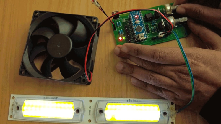
With an Arduino, a PC fan, and an LED strip, you can make a simple fume extractor that will keep you safe from the fumes from soldering.
Project info
Difficulty: Moderate
Platforms: PCBWay
Estimated time: 1 hour
License: Apache License 2.0 (Apache-2.0)
Items used in this project
Hardware components

Software apps and online services
Story
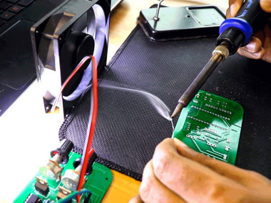
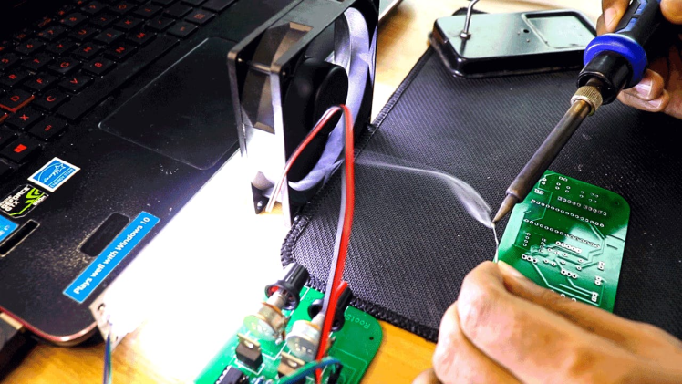
Soldering is awesome, right? It's fun to make our own PCB for our project, but there are a few things we need to watch out for as we solder the parts on. When we solder, we are around lead. Also, breathing in the fumes can cause long-term health problems, such as stomach problems, problems with memory and concentration, muscle and joint pain, and so on. Also, soldering parts onto the circuit board is hard on your eyes, and doing it in low light can eventually damage your eyesight permanently.
So, when soldering, it is very important to have enough light and a fume extractor to get rid of the smoke. By using a fume extractor, you and those around you will be safe from fumes that could be dangerous. In this video, we'll make a soldering fume extractor out of an old PC fan and a 12V LED strip that can be used to change the light.
So, the Arduino Nano is basically the brain of this project, but you can use any Arduino board. The input voltage is connected to a 7805 voltage regulator, which will turn the VIN into a steady 5V DC supply. There are two potentiometers here that are connected to the 5V and will act as voltage dividers. The outputs of the pots are connected to analog pins A0 and A1 respectively.
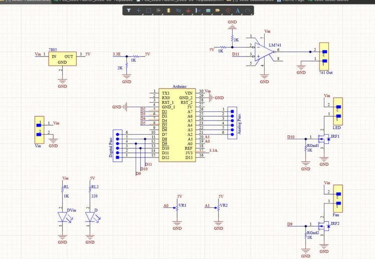
Here are two MOSFETs that are set up to work as switches. You can turn them on by turning on pin 9 and pin 10 of Arduino. Here, I'd like to point out that pins 9 and 10 are PWM pins, which means we can send PWM signals to the MOSFETs.
And here you can see an LM 741 comparator IC, which can be used to power any other devices you want. This is pretty much the whole circuit.

Once the circuit was done and tested, I used Altium to design a small PCB where I could put all the parts in a neat way. Here, you can see that routing is done on both sides of the board, which means it is a dual-layer PCB.
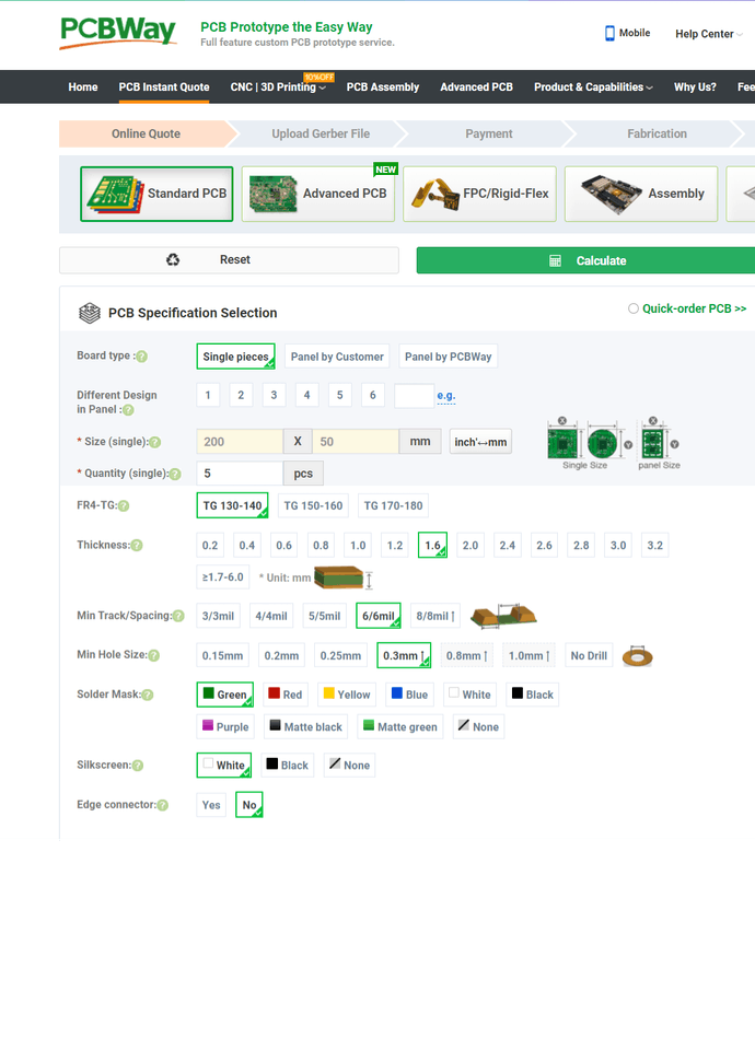
Getting the PCBs DonePCBWay is where I got PCB. PCBWay is a company that makes printed circuit boards (PCBs). They specialize in PCB prototyping, low-volume production, and clean PCB assembly. Check out the link below if you want to make your own PCBs for your project. You can save $5 when you sign up through the link below, and you can save another $5 when you check out by entering the coupon code PCBWayLab.

To order a PCB from PCBWay, go to the PCBWay website and fill out the instant order form with the board's basic information. From there, you'll be taken to a form where you can give more information about your board. Change the information about your board on the PCB specification screen. You should be able to upload your Gerber file and send it for review on the next screen. Once the review is done, all you have to do is add the PCBs to your cart, pay for them, and wait for them to arrive.
When you have all the parts and the PCB, you can solder them together. Put all the parts on the board by soldering them on, and make sure to check the polarity of the parts. This is how the PCB looks after the soldering is done.
CodingLet's get started coding right away. This is the code that will be uploaded to our Arduino when we complete the process. It seems to be fairly straightforward, doesn't it? To put it simply, it is easy!
const int ledPin =  13;
const int light = 9;
const int fan = 10;
int pot1 = 0;
int pot2 = 0;

void setup()
{
pinMode(ledPin, OUTPUT);
pinMode(A0, INPUT);
pinMode(A1, INPUT);
Serial.begin(9600);
}

void loop()
{
pot1 = map(analogRead(A0),0,500,0,255);
pot2 = map(analogRead(A1),0,500,0,255);
analogWrite(light, pot1);
analogWrite(fan, pot2);
delay(50);
Serial.println(pot1);
Serial.println(pot2);
Serial.println("");
}
To begin, we will be declaring some variables and then assigning them to the pins that will be often used throughout the course of this project. In the setup function, we are going to declare the pin mode, which is essentially going to tell the Arduino whether the pins are input pins or output pins.
We are taking the analog readings from the two pots, and within the loop function, we are mapping those readings to a value that falls somewhere in the range of 0 to 255. In the following line, we are going to turn on and off the MOSFETs that are connected to the Arduino Pins 9 and 10. To do this, we are going to output PWM signals with values that were generated from the lines that came before them.
Simply turning the potentiometer allows us to control not only the level of brightness produced by the LED strip but also the rate at which the fan rotates. A pipe or an outlet, to which this fan can be attached, can be used to ensure that the vapors do not remain contained within the room.
Schematics, diagrams and documents
Credits
Leave your feedback...