
Make Gps Border Boundaries Using Arduino

About the project
In this tutorial we will learn how to make a GPS BORDER BOUNDARIES using Arduino, this is useful when you have a robot,drone,etc
Project info
Difficulty: Moderate
Platforms: Adafruit, Arduino, Visuino
Estimated time: 1 hour
License: GNU Lesser General Public License version 3 or later (LGPL3+)
Items used in this project
Hardware components

Software apps and online services
Story
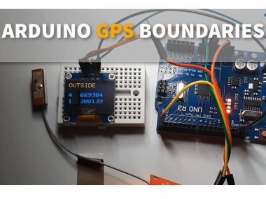
In this tutorial we will learn how to make a GPS BORDER BOUNDARIES using Arduino, this is useful when you have a robot and you dont want it to go outside the specified area.
When the robot is outside the area, the display will show "Outside" and "Inside" when the robot is inside the area.
Watch the video!
Step 1: What You Will Need
1 / 5
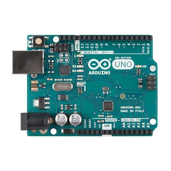


- Arduino UNO (or any other Arduino)
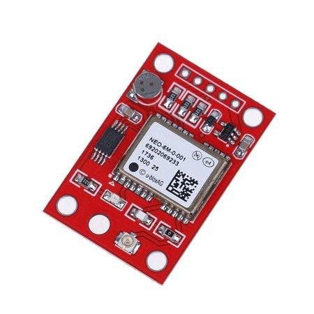
- GPS Neo 6m
- OLED Display
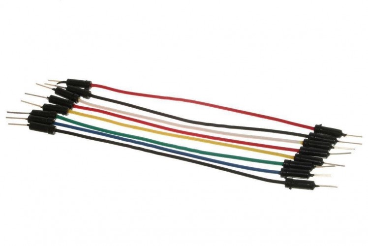
- Jumper wires
- Visuino software: Download Visuino
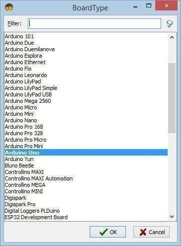
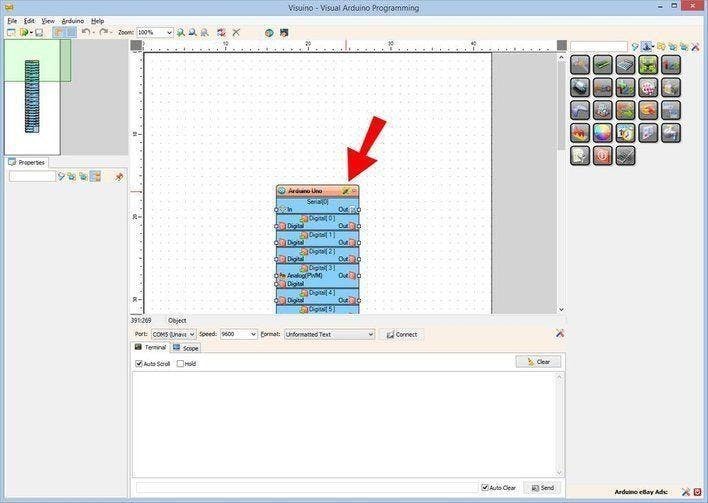
Step 2: Start Visuino, and Select the Arduino UNO Board Type
1 / 2
The Visuino: https://www.visuino.eu also needs to be installed. Download Free version or register for a Free Trial.
Start Visuino as shown in the first picture Click on the "Tools" button on the Arduino component (Picture 1) in Visuino When the dialog appears, select "Arduino UNO" as shown on Picture 2
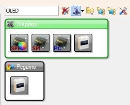
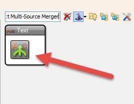
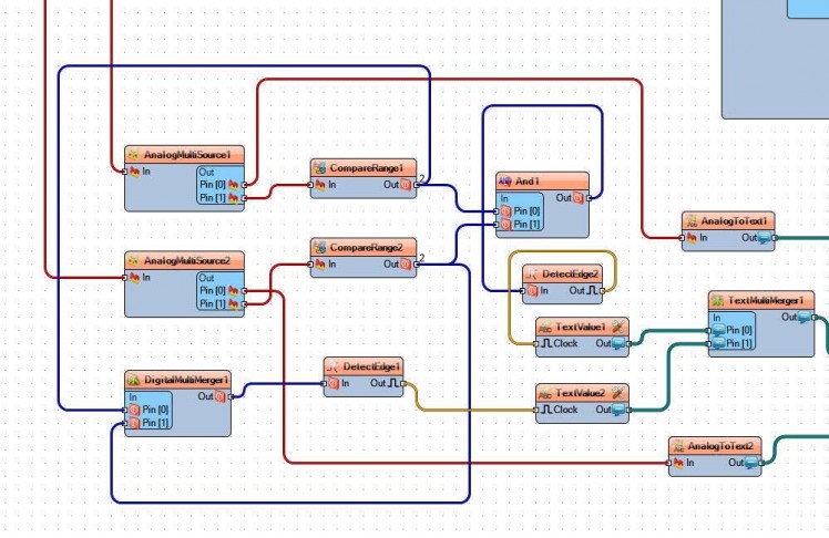
Step 3: In Visuino Add Components
1 / 10

- Add "Serial GPS" component
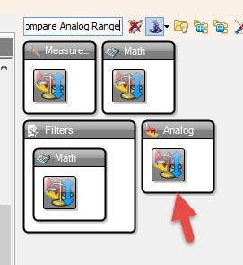
- Add "Analog Multi Source" component
- Add another "Analog Multi Source" component
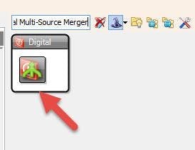
- Add "Digital Multi-Source Merger" component
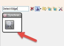
- Add "Detect Edge" component
- Add another "Detect Edge" component
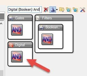
- Add "Digital (Boolean) And" component
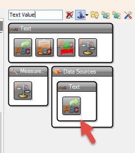
- Add "Text Value" component
- Add another "Text Value" component
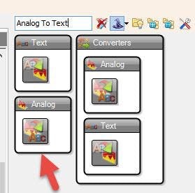
- Add "Analog To Text" component
- Add another "Analog To Text" component
- Add "Text Multi-Source Merger" component
Step 4: In Visuino Set Components
1 / 9
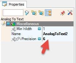
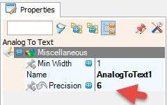
- Select "AnalogToText1" and "AnalogToText2" and in the properties window set "Precision" to 6
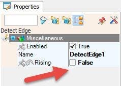
- Select "DetectEdge1" and in the properties window set Rising to False
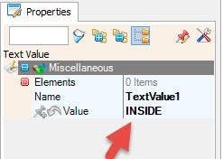
- Select "TextValue1" and in the properties window set "Value" to INSIDE
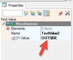
- Select "TextValue2" and in the properties window set "Value" to OUTSIDE
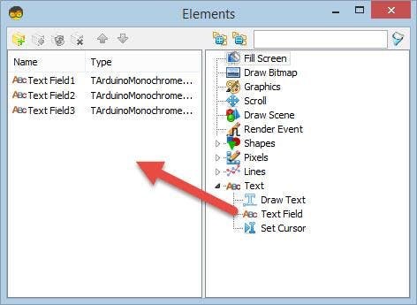
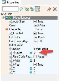
- Double click on the DisplayOLED1 and in the elements window drag "text field" to the left side
- In the properties window set size to 2
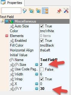
- In the Elements window Drag another "Text Field" to the left side
- In the properties window set Y to 30 and size to 2
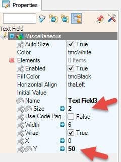
- In the Elements window Drag another "Text Field" to the left side
- In the properties window set Y to 50 and size to 2
- Close the Elements window
Step 5: Get GPS Coordinates
1 / 5
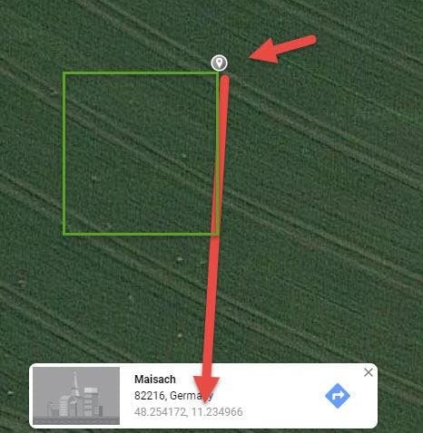
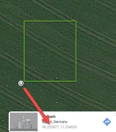
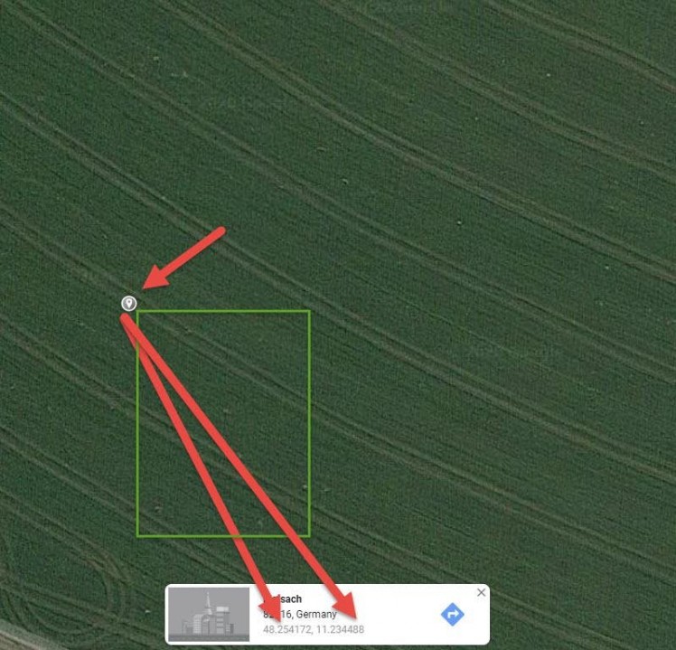
Go to Google maps and find your location and
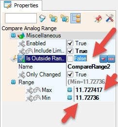
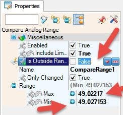
- Click on the map (upper left corner of your Area ), the coordinates will be shown at the bottom.Copy first coordinate Latitude to the Visuino "CompareRange1" > Range > MaxCopy second coordinate Longitude to the Visuino "CompareRange2" > Range > MIn
- Click on the map (upper right corner of your Area ), the coordinates will be shown at the bottom.Copy second coordinate Longitude to the Visuino "CompareRange2" > Range > Max
- Click on the map (down left corner of your Area ), the coordinates will be shown at the bottom.Copy first coordinate Latitude to the Visuino "CompareRange1" > Range > Min
Step 6: In Visuino Connect Components
1 / 3
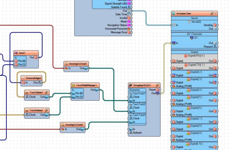

- Connect GPS pin Out to Arduino Serial[0] pin In
- Connect GPS pin latitude to AnalogMultiSource1 pin In
- Connect GPS pin longitude to AnalogMultiSource2 pin In
- Connect AnalogMultiSource1 pin Out to AnalogToText1 pin In
- Connect AnalogMultiSource2 pin Out to AnalogToText2 pin In
- Connect AnalogMultiSource1 pin Out to CompareRange1 pin In
- Connect AnalogMultiSource2 pin Out to CompareRange2 pin In
- Connect CompareRange1 pin Out to "And1", pin 0 In
- Connect CompareRange2 pin Out to "And1", pin 1 In
- Connect CompareRange1 pin Out to DigitalMultiMerger1, pin 0 In
- Connect CompareRange2 pin Out to DigitalMultiMerger1, pin 1 In
- Connect DigitalMultiMerger1, pin Out to DetectEdge1 pin In
- Connect DetectEdge1 pin Out to TextValue2 pin clock
- Connect "And1" pin out to DetectEdge2 pin In
- Connect DetectEdge2 pin out to TextValue1 pin clock
- Connect "TextValue"1, pin out, to TextMultiMerger1 pin [0] in
- Connect "TextValue"2, pin out, to TextMultiMerger1 pin [1] in
- Connect TextMultiMerger1 pin Out to DisplayOLED1 text field1 pin In
- Connect AnalogToText1 pin Out to DisplayOLED1 text field2 pin In
- Connect AnalogToText2 pin Out to DisplayOLED1 text field3 pin In
- Connect DisplayOLED1 pin I2C Out to Arduino pin I2C In
Step 7: Generate, Compile, and Upload the Arduino Code
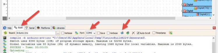
Important!
When uploading to Arduino disconnect the pin RX on the Arduino and after the uploading is done reconnect it back.
In Visuino, at the bottom click on the "Build" Tab, make sure the correct port is selected, then click on the "Compile/Build and Upload" button.
Step 8: Play
If you power the Arduino module, after a while (when NEO 6m calibrates), the display will start to show GPS coordinates and text: INSIDE/OUTSIDE.
Congratulations! You have completed your project with Visuino. Also attached is the Visuino project, that I created for this tutorial, you can download it and open it in Visuino: https://www.visuino.eu
Schematics, diagrams and documents
Code
Credits
Related products


Leave your feedback...