
Make Diy Homework Writing Machine At Home

Made by diy-projects-lab / 3D Printing / Artificial intelligence / Games & Gaming
About the project
Drawing Robot/Pen Plotter/Drawing Machine is an Open Hardware version of the famous machine AxiDraw which it is a pen plotter, capable of wr
Items used in this project
Hardware components

Story


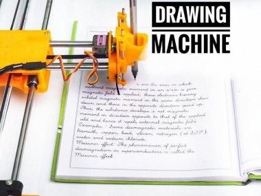
Drawing Robot/Pen Plotter/Drawing Machine is an Open Hardware version of the famous machine AxiDraw which it is a pen plotter, capable of writing or drawing on almost any flat surface. It can write with pens, permanent markers, pencils, and other writing implements to handle an endless variety of applications.
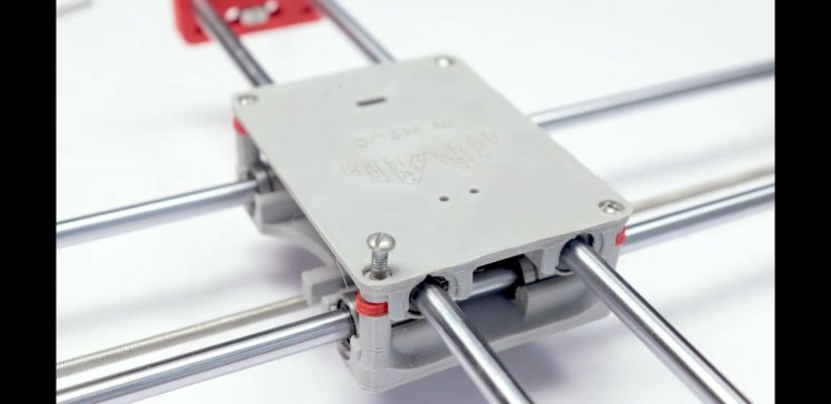
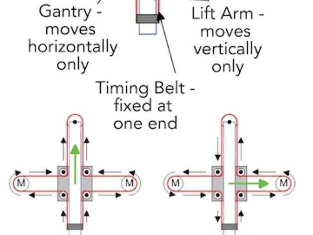
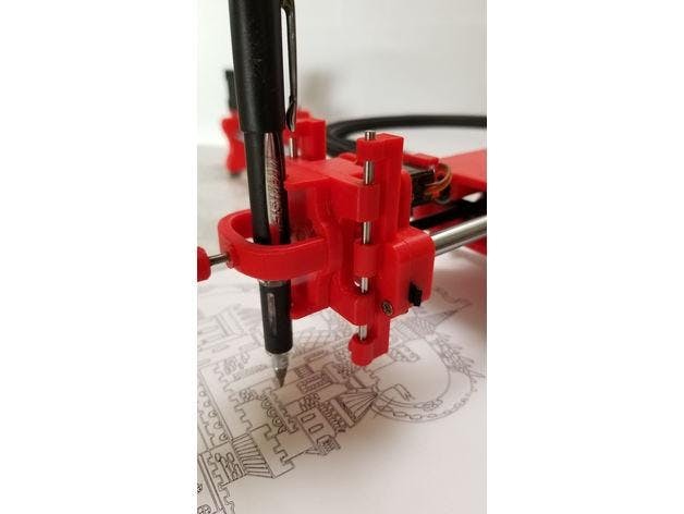
Its unique design features a writing head that extends beyond the machine, making it possible to draw on objects bigger than the machine itself. The biggest advantage of the machine is that it can be placed over the book because of the core XY extending design of the machine.
This Drawing Robot/Pen Plotter/Drawing Machine is similar to the commercially available AxiDraw. It is powered by an Arduino Uno controller, uses a CNC Shield, and GRBL firmware
The cost to build the Drawing Robot is between $75 depending on where you buy your parts and whether you already own some of the parts such as the Arduino.
You can find all of my projects on https://www.diyprojectslab.com/
Maximum drawing area 24 * 30 CM.
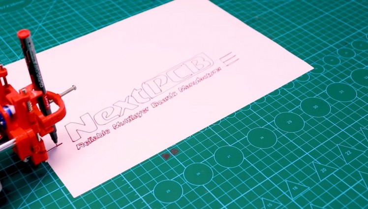
Thank You NextPCB
This project is successfully completed because of the help and support from NextPCB. Guys if you have a PCB project, please visit their website and get exciting discounts and coupons.
Free shipping 0$ PCB Prototype:https://www.nextpcb.com/pcb-quote?act=2&code=Romeo...
Thanksgiving Christmas lucky draw 100% win: https://www.nextpcb.com/christmas-lucky-draw?code...
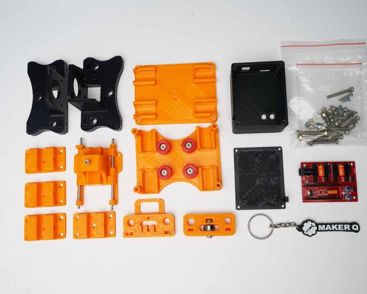
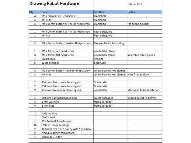
Step 1: Parts and Materials Required
1 / 2
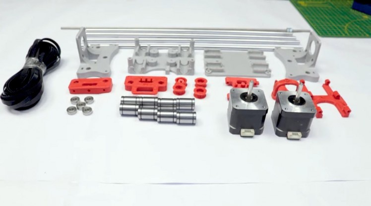
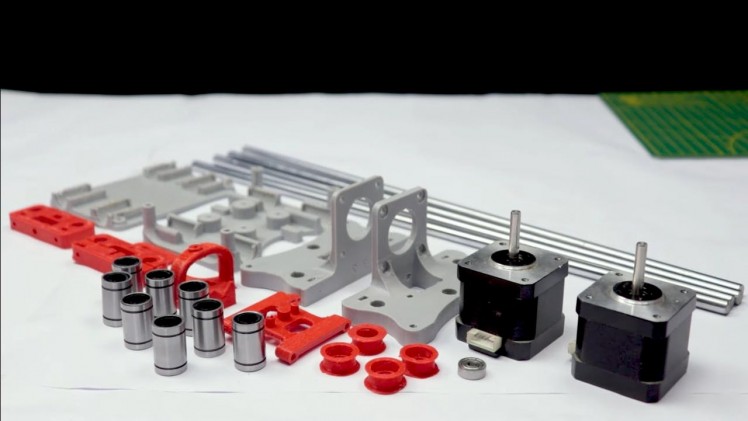
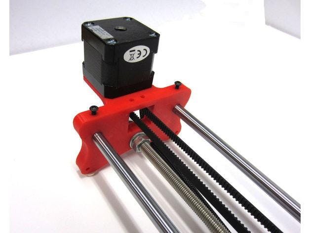
2 x Nema 17 Stepper Motors Amazon.com
2 x Linear Rod M8 x 450mm for X Axis Amazon.com
2 x Linear Rod M8 x 350mm for Y Axis Amazon.com
2 x Linear Rod 3mm for Z Axis (you can get it from old CDROM)
1 x Threaded Rod M8 x 480mm8 x LM8UU Bearings Amazon.com
1 x Servo Sg901 x Spring 5m (from ball point pen) Amazon.com
2 x GT2 Pulley, 16 teeth Amazon.com
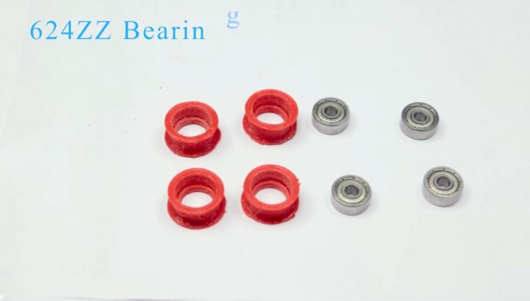
5 x Bearing 624zz Amazon.com
1 x 2000mm GT2 belt Amazon.com
1 x Arduino Uno Amazon.com
1 x CNC Shield Amazon.com
2 x A4988 Stepper driver with heatsink Amazon.com
6 x Jumpers Amazon.com
1 x 12V 2A Power Supply Amazon.com
Nuts
- 7 x M3-0.5
- 5 x M4-0.7
- 4 x 5/16in-18
Screws
- 13 x Phillips M3-0.5 x 16mm
- 4 x Phillips M3-0.5 x 6mm
- 5 x Phillips M4-0.7x 35mm
- 1 x Hex M3-0.5 x 20mm
Washers
- 4 x 5/16in washer
- 4 x M3 washers
1 / 2
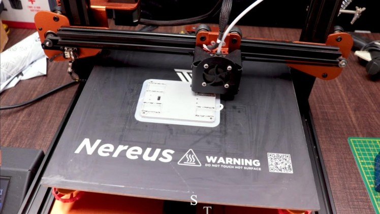
Download the files from Thingiverse
Open the 3D models in Cura or any other slicer.
Use 75% infill on all the parts (An infill of 70 – 100% will work as well)
Printed all the parts with 0.10 – 0.20 mm layer height
Printed with PLA
Use supports on the Penholder, Slider, X_Support_L and the X_Support_R
Note: The longest part took around 10hrs and the shortest took 30 minutes to print
PLA is fine for this design. I print at 200C on BuildTak. None of the parts require rafts or brims. I suggest supports only for the pen holder and the Z axis end plate which is standing up.
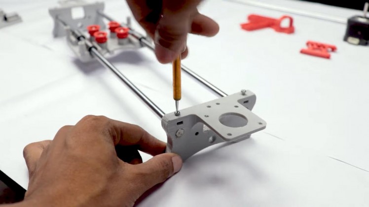
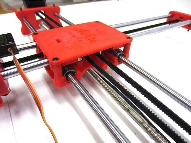
Step 3: Assemble the X-Axis
1 / 2
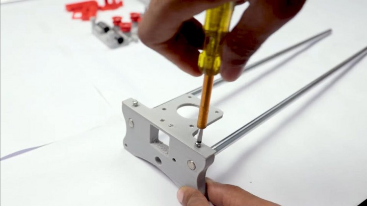
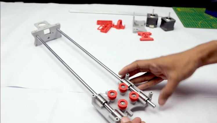
Remember that you need (2) 350mm and (2) 450mm long linear rods
Take the (2) 450mm linear rods and insert them into either x-support part
- Use may need to use a round file to smooth out the holes that you insert them in
- Also, you can use a rubber mallet to help insert the rods
Now take the threaded rod and insert it in the hole below. Feed a 5/16in washer and 5/16in nut on both sides of the x-support part
Step 4: Assemble the X-Axis Bearing
1 / 6
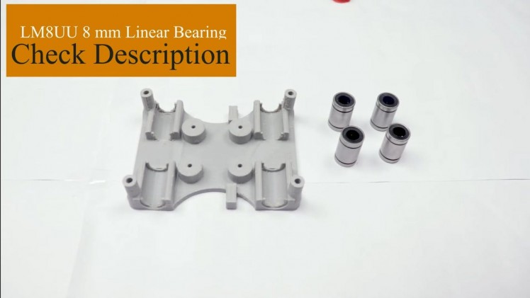
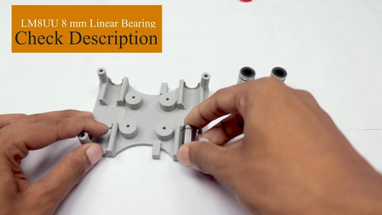
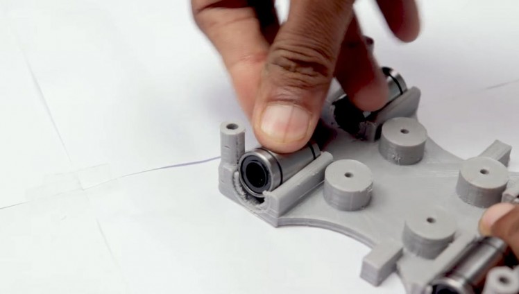
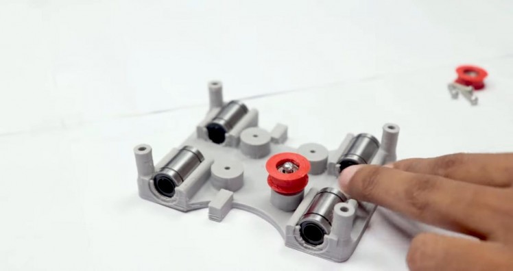
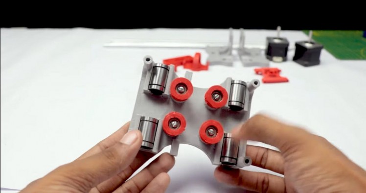
Now you want to push the LM8UU bearings into their place on the top and bottom clamshell (The top and bottom clamshell take (4) bearings each)
Take (4) 624zz bearings and push them through the 3D-printed idler pulleys. Leave the 5th bearing for later when you assemble the Y-axis
Assemble the X-Axis (Carriage)
- Get (4) M3-0.5 x 20mm screws, (4) M3 nuts, (4) M3 washers and (4) 624zz bearings with the idler pulleys installed
- Take one screw and feed a washer through it, the washer will rest on the bearing. The nut will be at the bottom of the carriage, which will secure the bearing in place
Assemble the X-Axis (X-Support)
- Slide the clamshell through the 450mm (X-axis) linear rods
- Use a rubber mallet again to attach the last X-support on the linear rods
- Make sure that the rods stick out equally on both sides
- Slide the other end of the threaded rod through the hole on the X-support
- Put on the last set of nuts and washers to hold the X-support in place
- Now that the X-axis is complete, you can use (2) Phillips M3-0.5 x 16mm screws per X-support to help keep the linear rods from sliding
1 / 3
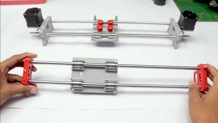
Y-Back
- Take the (2) 350mm linear rods and insert them the Y-back piece by using a rubber mallet
- Get (1) M4-0.5 x 35 screw, (1) M4 nut and the 5th 624zz bearing
- Get (2) M3-0.5 x 16 screws to secure the linear rods
- Slide in the bearing when inserting the screw through the Y-back piece
Y-Front
- Slide the the linear rods/Y-back piece through the LM8UU bearings and attach the Y-front piece using a rubber mallet
1 / 3
- Use a pair of needle nose pliers to help guide the GT2 belt more easily through the clamshell
- Take the two ends of the belt and slide them through the “teeth” on the Base Slider
- The belt should be tight and not loose
- Note that once the GT2 belt is on, it is normal for the clamshell not to move easily
1 / 3
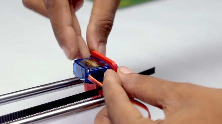
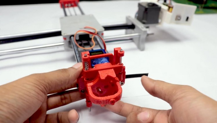
- Get (2) 3mm linear rods and the following 3D printed parts (Slider, Pen Holder, Base Slide, 3MM Metric Thumb Screw)
- Get (1) Hex M3-0.5 x 20mm screw and the Metric Thumb Screw and push them together. Use superglue to keep it together.
- Get (3) M3-0.5 x 16mm screws which you will use the secure the Base Slide to the Y-Front part. You may need to use (3) M3-0.5 nuts in order to hold it in place
- Push the Slider and Pen Holder together to make one piece
- Now take that new part and the (2) 3mm linear rods and slide the rods through the holes. Place a small spring in between the two parts so there is a little bit of pressure to lift the Slider. You may need to cut the spring a bit until there is an adequate amount of pressure on the slider.
1 / 3
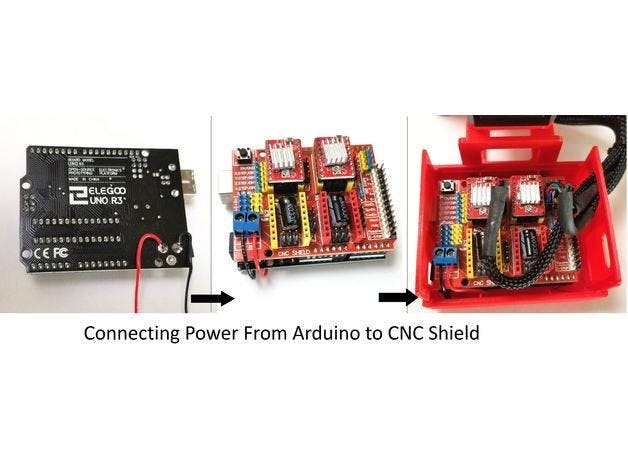
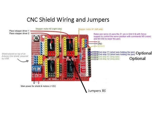
ELECTRONICS
I prefer you can use Arduino uno CNC Shield
Ready to your all circuit
1) 4pcs A4988 Stepper Motor Driver
2) Expansion Board A4988 Driver
3)Arduino UNO First of all take hit sink and stick on A4988 motor Driver.
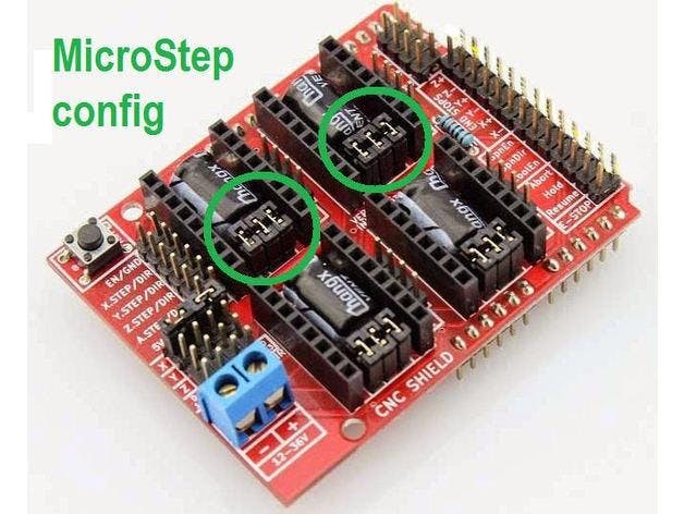
4pcs A4988 Stepper motor driver connect on expansion board A4988 driver module, then connect the arduino with expansion board and connect all wiring The shield also has a built-in micro stepping control - meaning that instead of using full steps or half steps like a large CNC would do, we can make the motors move by 1/16 or 1/32 of a step to make the laser move with the maximal precision possible. However, the motors will consume more electricity: they will get hot quicker.
To use the micro stepping modes, short some of the mode pins together. Different combinations give different resolutions. Take a look at the chart for the different configurations possible. When the shield is programmed, add the A4988 drivers to it and wire up the rest of the electronics.
To find the coils of the stepper motors, use a multimeter. If there's resistance between the two wires, you have a coil. On the schematic, the coils are represented by two wires of the same color.
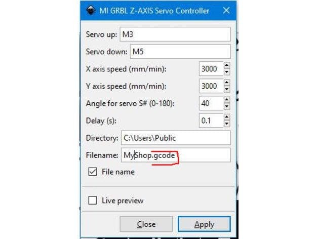
Step 9: SOFTWARE
1 / 8
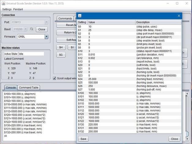

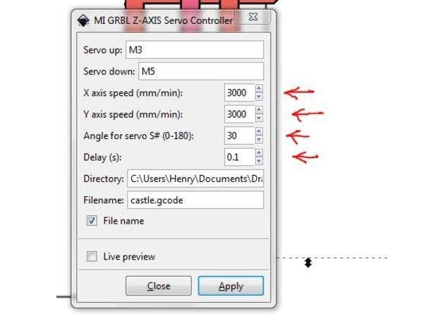
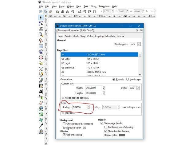

Inkscape which is the graphics design software (draw or import graphics)
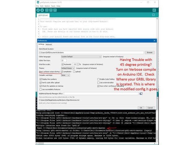
Inkscape MI GRBL Extension (convert graphics to G-Code)Universal G Code Sender (sends the G-Code to the robot causing drawing motion)GRBL which is the Arduino firmware (programmed into the Arduino Uno)
Arduino: https://www.arduino.cc/en/software
Universal G-code sender: https://winder.github.io/ugs_website/...
Inkscape: https://inkscape.org/release/inkscape..
4xiDraw & km laser: https://drive.google.com/file/d/1YO8-...
Processing: https://processing.org/download/
drawing to G-code processing: https://drive.google.com/file/d/1PIFx...
watch video for full setup
Step 10: Drawing Machine at WorkSchematics, diagrams and documents
Code
Credits
Related products


Leave your feedback...