
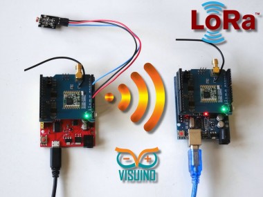
Long Distance Remote Light Sensor With Rfm95w/rfm98w Lora

Made by Ron / Communication / Sensors / IoT
About the project
Send light sensor data over long distance with RFM95W/RFM98W Makerfabs LoRa Shields. Quick and easy!
Project info
Difficulty: Easy
Estimated time: 1 hour
License: GNU General Public License, version 3 or later (GPL3+)
Items used in this project
Hardware components

Software apps and online services
Story
There are many wireless communication options when connecting Arduino boards. One of the most popular ones is the Wi-Fi. It works well at small distances, and around Wi-Fi hotspots, however when the modules need to connect over long distance at areas where Internet is not present, Wi-Fi is not an option. Luckily there is a great and easily available alternative - the LoRa (Long Range Wide-area network) modules allow sending small packets of data between modules over very long distances (5 Km or more) .
Visuino has support for a number of LoRa Modules, and I was planning tutorial for quite some time, since I had some Adafruit LoRa modules. However, recently the great people at Makerfabs, sent me 2 RFM95W 868MHz based LoRa Shields, and even a great Arduino UNO compatible Maduino UNO board. The Makerfabs modules are of exceptionally good quality, and I decided to make this tutorial with them.
In this tutorial I will show you how easy it is to install the LoRa shields on 2 Arduino UNO boards, and program them with Visuino to transmit data over long distance.
Step 1: Components- Two Arduino UNOcompatible boards (I use one Arduino UNO generic clone, and one Maduino UNO from Makerfabs, but any other will be just fine)
- Two Makerfabs LoRa Radio Shields ( RFM98W 433MHz, or RFM95W 868MHz ) Make sure both shields are the same type, otherwise they will not be able to communicate
- One Photoresistor Sensor module I got from this cheap 37 sensors set
- 3 Female-Male jumper wires
1 / 6 • Picture 1

Picture 1

Picture 2

Picture 3

Picture 4

Picture 5

Picture 6
First we will assemble the Sending Arduino project:
- Plug the LoRa Shield on top of the Arduino Uno as shown on the Pictures 1, 2, 3, and 4 and on the Video
- Connect Female ends of the Ground(Black wire), Power(Red wire), and Signal(Blue wire) to the Photoresistor Module (Picture 5)
- Connect the other end of the Ground wire(Black wire) to the Ground pin of the Arduino board (Picture 6)
- Connect the other end of the Power wire(Red wire) to the 5V power pin of the Arduino board (Picture 6)
- Connect the other end of the Signal wire(Blue wire) to the Analog pin 0 of the Arduino board (Picture 6)
1 / 3 • Picture 1

Picture 1

Picture 2

Picture 3
To start programming the Arduino, you will need to have the Arduino IDE installed from here: http://www.arduino.cc/.
Make sure that you install 1.6.7 or higher, otherwise this tutorial will not work!
The Visuino: https://www.visuino.com also needs to be installed.
- Start Visuino as shown in the first picture
- Click on the "Arrow Down" button of the Arduino component to open the Drop Down Menu (Picture 1)
- From the Menu select "Add Shields..." (Picture 2)
- In the "Shields" dialog expand the "Communication" category, and select the "Makerfabs RFM95/96/97/98 LoRa Shield", then click on the "+" button to add it (Picture 3 )
1 / 5 • Picture 1

Picture 1

Picture 2

Picture 3

Picture 4

Picture 5
We will send to the LoRa Shield the value of Analog Channel 0 once a second. For this we need to use "Analog Snapshot" component, and to clock it once a second with the "Clock Generator":
- Type "snapshot" in the Filter box of the Component Toolbox then select the "Analog Snapshot" component (Picture 1), and drop it in the design area
- Connect the "Out" pin of the "Digital[ 14 ]/AnalogIn[ 0 ]" channel of the Arduino component to the "In" pin of the AnalogSnapshot1 component (Picture 2)
- Connect the "Out" output pin of the AnalogSnapshot1 component to the "In" input pin of the "Shields. RFM9X LoRa" element of the Arduino component (Picture 3)
- Type "clock" in the Filter box of the Component Toolbox then select the "Clock Generator" component (Picture 4), and drop it in the design area
- Connect the "Out" output pin of the ClockGenerator1 component to the "Snapshot" input pin of the AnalogSnapshot1 component (Picture 5)
1 / 2 • Picture 1

Picture 1

Picture 2
- Connect the Sending Arduino (the one that has the Light Sensor) to the computer with the USB cable
- In Visuino, Press F9 or click on the button shown on Picture 1 to generate the Arduino code, and open the Arduino IDE
- In the Arduino IDE, click on the Upload button, to compile and upload the code (Picture 2)
1 / 4 • Picture 1

Picture 1

Picture 2

Picture 3

Picture 4
Now it is time to assemble the Receiving Arduino project:
Plug the second LoRa Shield on top of the second Arduino Uno as shown on the pictures, and in the Video
Step 7: In Visuino: Create New Visuino Project, and Add LoRa Shield to the Arduino Component
1 / 3 • Picture 1

Picture 1

Picture 2

Picture 3
- Create new Visuino project as shown in the first picture
- Click on the "Arrow Down" button of the Arduino component to open the Drop Down Menu (Picture 1)
- From the Menu select "Add Shields..." (Picture 2)
- In the "Shields" dialog expand the "Communication" category, and select the "Makerfabs RFM95/96/97/98 LoRa Shield", then click on the "+" button to add it (Picture 3 )
1 / 2 • Picture 1

Picture 1

Picture 2
We will send the serial data that we receive from the LoRa Shield to the computer through the Serial Port . For this we need to connect the two ports:
- Connect the "Out" output pin of the "Shields.RFM9X LoRa" Shield of the Arduino component (Picture 1) to the "In" input pin of the "Serial[ 0 ]" channel of the Arduino component (Picture 2)
1 / 2 • Picture 1

Picture 1

Picture 2
- Connect the Receiving Arduino to the computer with the USB cable
- In Visuino, Press F9 or click on the button shown on Picture 1 to generate the Arduino code, and open the Arduino IDE
- In the Arduino IDE, click on the Upload button, to compile and upload the code (Picture 2)
1 / 6 • Picture 1

Picture 1

Picture 2

Picture 3

Picture 4

Picture 5

Picture 6
Picture 1 and the Video shows the connected and powered project.
On Picture 2 you can see the complete Visuino diagram of the Sending project.
On Picture 3 you can see the complete Visuino diagram of the Receiving project.
If you connect to the receiving module with Serial Terminal from the Arduino IDE or Visuino (Picture 4), you will see the data arriving in the Terminal (Picture 5). You can also monitor the data in the Scope (Picture 6). However if there are other similar modules in the area, transmitting packets on the same frequency, our receiving module will receive and display them. In the following steps of the tutorial, I will show you how to ignore such packets.
Also attached are the Visuino projects, that I created for this Tutorial. You can download and open them in Visuino: https://www.visuino.com
Step 11: In Visuino: Add and Connect "Add Packet Header ID" Component
1 / 4 • Picture 1

Picture 1

Picture 2

Picture 3

Picture 4
To make sure that we process by the receiving LoRa module only the packages sent from our sending LoRa module, we can add a unique ID at the beginning of each packet and ignore received packets that do not have the ID . For this we can use the "Add Packet Header ID" to add the packet in the sender, and "Detect Packet Header ID" to check if the packet has the ID in the receiver.
First we will modify the Sending Project:
- Reopen the Sending project
- Type "packet" in the Filter box of the Component Toolbox then select the "Add Packet Header ID" component (Picture 1), and drop it in the design area
- Disconnect the old connection between the "Out" output pin of the AnalogSnapshot1 component to the "In" input pin of the "Shields. RFM9X LoRa" element of the Arduino component (Picture 2) by right clicking on the connection and selecting "Disconnect link" from the popup menu
- Connect the "Out" output pin of the AnalogSnapshot1 component to the "In" input pin of the AddPacketHeaderID1 component (Picture 3)
- Connect the "Out" pin of the AddPacketHeaderID1 component to the "In" pin of the AnalogSnapshot1 component (Picture 4)
1 / 2 • Picture 1

Picture 1

Picture 2
Next we need to set the bytes of the unique header. In my case I set "34, 67" but you should enter your own values. Enter at least 2 bytes, and probably no more than 20:
- In the Properties, click on the "..." button next to the value of the "ID" property of the AddPacketHeaderID1 component (Picture 1)
- In the Bytes editor type some numbers, as example 34 67
- Click on the OK button to confirm and close the editor
- Connect the Sending Arduino (the one that has the Light Sensor) to the computer with the USB cable
- In Visuino, Press F9 or click on the button shown on Picture 1 of Step 5 to generate the Arduino code, and open the Arduino IDE
- In the Arduino IDE, click on the Upload button, to compile and upload the code as you did in Step 5
1 / 3 • Picture 1

Picture 1

Picture 2

Picture 3
Now it is time to modify the Receiving Project by adding "Detect Packet Header ID" component to check if the packet has our ID:
- Reopen the Receiving project
- Type "packet" in the Filter box of the Component Toolbox then select the "Detect Packet Header ID" component (Picture 1), and drop it in the design area
- Disconnect the old connection between the "Out" output pin of the AnalogSnapshot1 component to the "In" input pin of the "Shields. RFM9X LoRa" element of the Arduino component (Picture 2) by right clicking on the connection and selecting "Disconnect link" from the popup menu
- Connect the "Out" output pin of the AnalogSnapshot1 component to the "In" input pin of the AddPacketHeaderID1component (Picture 3)
- Connect the "Out" pin of the AddPacketHeaderID1component to the "In" pin of the AnalogSnapshot1 component (Picture 4)
- In the Properties, click on the "..." button next to the value of the "ID" property of the DetectPacketHeaderID1 component (Picture 1)
- In the Bytes editor type the same numbers as in our sensing project (in my case 34 67 )
- Click on the OK button to confirm and close the editor
1 / 4 • Picture 1

Picture 1

Picture 2

Picture 3

Picture 4
- Disconnect the "Out" output pin of the "Shields.RFM9X LoRa" Shield of the Arduino component from the "In" input pin of the "Serial[ 0 ]" channel of the Arduino component (Picture 1) by right clicking on the connection and selecting "Disconnect link" from the popup menu
- Connect the "Out" output pin of the "Shields.RFM9X LoRa" Shield of the Arduino component to the "In" input pin of the DetectPacketHeaderID1 component (Picture 2)
- Connect the "Out" output pin of the DetectPacketHeaderID1 component (Picture 3) to the "In" input pin of the "Serial[ 0 ]" channel of the Arduino component (Picture 4)
- Connect the Receiving Arduino to the computer with the USB cable
- In Visuino, Press F9 or click on the button shown on Picture 1 of Step 9 to generate the Arduino code, and open the Arduino IDE
- In the Arduino IDE, click on the Upload button, to compile and upload the code as you did in Step 9
1 / 6 • Picture 1

Picture 1

Picture 2

Picture 3

Picture 4

Picture 5

Picture 6
Picture 1 and the Video shows the connected and powered project.
On Picture 2 you can see the complete Visuino diagram of the modified Sending project. The components has been moved around to make the design easier to follow.
On Picture 3 you can see the complete Visuino diagram of the modified Receiving project.
If you connect to the receiving module with Serial Terminal from the Arduino IDE or Visuino (Picture 4), you will see the data arriving in the Terminal (Picture 5). You can also monitor the data in the Scope (Picture 6).
Now if there are other modules in the area transmitting on the same frequency, and with the same transmitter model, their packets will be ignored.
Also attached are the modified Visuino projects, that I created for this Tutorial. You can download and open them in Visuino: https://www.visuino.com
Credits
Related products


Leave your feedback...