
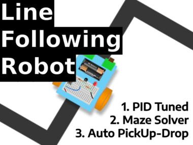
Line Follower Robot - King Of Maze

Made by akshayan-sinha / Robotics / Sensors / Vehicles / Virtual Reality / IoT
About the project
Automated item delivery through shortest available path - Useful in industries for pick and drop cases - no requirement of ROS.
Project info
Difficulty: Difficult
Platforms: Espressif, MQTT, PCBWay
Estimated time: 1 hour
License: GNU General Public License, version 3 or later (GPL3+)
Story
? More such tutorials, and projects on Embedded systems and IoT, follow Akshayan Sinha on Hackster (https://www.hackster.io/akshayansinha) ?
What is an LFR?
LFR stands for Line Following Robot. The line it follows could be white, black, any other color, or even transparent. All that matters is, the robot must follow the line.
Even though it sounds simple, it is a struggle for most of the 1st Year Engineering students. It is a struggle to understand, then implement, then analyze the errors, and make corrections accordingly. After a couple of days, most likely a week, an LFR is finally ready to be run on a line.
This article however does not contain any code, on how to make it. We shall only share an example of the LFR robot in the form of a video.Y for ordering PCBs online for cheap!
You get 10 good-quality PCBs manufactured and shipped to your doorstep for cheap. You will also get a discount on shipping on your first order. Upload your Gerber files onto PCBWAY to get them manufactured with good quality and quick turnaround time. PCBWay now could provide a complete product solution, from design to enclosure production. Check out their online Gerber viewer function. With reward points, you can get free stuff from their gift shop.
Get Started
Line Following Robots are pretty basic and have readily-available instructions on building them on the Internet. Keeping the usual LFR aside, the one we shall be building is different. Why is that?1. It has a purpose.2. It is pretty smart.
In other words, this LFR is an "IoT-based SmartPID tunedMaze Solver". It can be put anywhere in the maze, and let the robot do a dry run. While performing the dry run, it maps the whole maze and waits for the user to provide a destination. During the speed run, on providing a destination, the LFR reaches the spot through the shortest path available.
Let us proceed further, by following a roadmap to achieve the goal -
Background
Let us first understand how the data shall proceed to be captured, shared to the internet, and converted to a visual map.
Since we shall be using the IR Sensor Array to keep reading the Line, we also require to know the distance of every path so that the map drawn out is accurate and does not have a false narrative on which path to proceed with.
- Using a rotary encoder, and a simple formula, find the distance of every path before there is a turn on the path. Then, based on the turn it takes (left or right) we'd also get the turns to be shared with the cloud.
- We can further store the data on the cloud in a server or even a JSON string. It can be comma/hyphen separated, and similar to 'F10-R-F20-L-F5-L-F15-R-F10'. In this case, F - Forward, R - Right, L - Left, and based on the distance (in cm) we get the numbers on how far the robot went forward. For example - F10 = forward for 10 cms. Most likely the data would be stored on a JSON server.
- Building an interactive Map, it is time-consuming. It also comes under the 'Expert' level in explaining the steps of building the whole project.
- The data from the JSON is later received on the Web Application, where the data goes under a few steps to create a visualization of the Path Map. This path map should be interactive, i.e. every vertex and start/end of the line should have a node point on it. This node point must act like a button, that is used for - Recalling the bot in the location- Setting Pickup/Drop Location- Avoid the path through the node
This map can later be used for tracking the position of the robot. So, whenever there is a breakdown or required to reach the spot of the robot the exact location can be noted.
Read Maze Map using a Dry Run
Now that the whole concept is clear, let us begin with the steps on reading and storing the Path Map in the cloud -
- There are 2 cases when it should stop reading the map, and follow other commands -1. When there is a loop, the robot may infinitely keep looping within the loop. To avoid this case, a part of the application will send a change in methodology to come out of the loop.2. When the robot reaches the starting point, it should turn halt, and wait for the next commands
- When trying the build a maze solver, there is a concept of - Left Hand Rule & Right Hand Rule.
- In the story Maze, it is said that - Any maze that has a starting and ending point, the one thing that connects both apart from the path, is the side walls. Let us understand - 1. Walking through a maze, while placing the right hand on the right side wall.2. Without any 2nd thoughts, take every right turn that comes while going ahead.3. Eventually, we shall reach the end of the maze.

- Let us take the above example. We shall put our robot on the START point and find the number of steps till it reaches the END point.Notation used - F = Forward, L = Left, R = Right, UF = Backward, U = U Turn
- If the robot is based on LHR - FLFFUFLFFFLFUFLFRFLFUFLFIf the robot is based on RHR - FLFRFRFLFLFRFFRFFrom the above example, we find out the RHR is much better for this path map.
- You might have noticed we have taken the right turns in LHR and vice versa. It is necessary in cases when there is no other path (right or forward).
- Now that we know how to read movements, let us further put it in detail using the rotary encoder. The goal is to have a string somewhat like below text -F5-L-F5-F5-U-F5-L-F10-F5-F5-L-F5-U-F25-L-F10-R-F2-L-F5-U-F5-L-F3
- The purpose is to convert the above text into a turtle's drawing mechanism and visualize a custom map on the Web Application.
Send Map data to Cloud
To be able to handle major traffic to be able to send data across the device and cloud, we require a reliable service. For that purpose, we shall be using Google Firebase's Serverless Database.
- This database uses JSON to store information/data. Therefore it is a perfect fit for this project. Go through this Project on Google Firebase to set up an account and create a serverless database.
- Use a JSON similar to below to make sure the data is received on the cloud -
{
    "BOT_ID": "X-Boomer LFR",
    "path": "F5-L-F5-F5-U-F5-L-F10-F5-F5-L-F5-U-F25-L-F10-R-F2-L-F5-U-F5-L-F3"
}- On the cloud, or at the edge, the existing directions can be converted to a map using JS functions. There is a method whose part can be taken for this purpose - FreeCodeCamp Map Generator Article
- The map can later be applied with buttons for each node, to generate start and endpoints. The LFR would directly complete the lap through the shortest path.
Shortest path between locations X & Y
In a maze, for locomotion from one point to another, there is more than one way to reach the spot. But the question is, which is the shortest path to reach the spot? A maze consists of 90º sharp turns. So, we shall consider that, and find a logic to find the shortest path, using a simple algorithm.
- We have noticed earlier, what the path(text) for the LFR looks like. For a robot based on LHR - FLFFUFLFFFLFUFLFRFLFUFLF
- But this path is not the shortest path for the robot, since taking the extra turns utilizes more time. By avoiding the extra roads that need not be taken, we would ultimately find the shortest path to move from Start to End.
- There is a method to calculate, which is to avoid and remove the below abstracts from any path(text). This removal needs to be done repeatedly, even on the result after one cycle. Abstracts - LFUFR = UFLFUFF = RLFUFRF = UFFUFL = RFUFF = UFLFUFLF = F
- For example for - FLFFUFLFFFLFUFLFRFLFUFLFAbove, after the first trial of removing abstracts - FLFRFFFFRFF
- Now, we can use the data of distance to cover in the shortest time. Make sure the total distance for forwarding is taken into account. For example, if the forwards are 10, 5, 5, 10 before any turn or end. Such instances are FFFFR and RFF.
- We shall insert the forward with the total distance in this case -F10-F5-F5-F10-R, In this case, we shall put the total, i.e. 10+5+5+10 = 30.Finally, we shall have FLFRFRF.
- In terms of distance, it is - F5-L-F5-R-F30-R-F5
Now that we have the shortest path along with distance, we require a control system to move the bot in a shorter time to reach the destination. We can use the PID control for speed manipulation based on position, path and distance.
What is PID? Learn and Implement
To make sure the shortest distance also moves faster in long straight paths, we require a moto speed control system. Along with that, we need a PID control system to find the fastest safe seed way to cover the distance in a short time.
- The focus is to have a higher speed in a bell curve graph visualization -
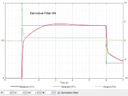
- Here, on the Y axis, we have the speed. And mapped the path of that particular path over every step of distance.
- From 1 to 3, there would be a gradual increase in speed, with high speed in the 3 positions, and as it reaches the end (pos - 4), the speed decreases.
- The increase & decrease in speed is required for, gradually exiting and entering sharp turns.
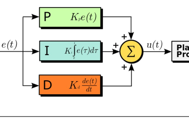
This control system is performed using PID Control. Which stands for Proportional - Integral - Derivative. But what is it?
What is a Control System?
A control system is a system, which provides the desired response by controlling the output. There are two major types - Open & Closed Loop system
What is a Control Loop?
Open loop systems are regular predefined inputs that provide output depending on the Input provided.
Open Loop

Open Loop
But the Closed loop system is a feedback-driven system, where the new output depends on the previous output, and whether it matches the defined set point after removing the error in a new value.
Closed Loop

Closed Loop
Effect of Feedback on StabilityA system is said to be stable if its output is under control. Otherwise, it is said to be unstable. In negative feedback (T=G/(1+GH)), if the denominator value is zero (i.e., GH = -1), then the output of the control system will be infinite. So, the control system becomes unstable.
Therefore, we have to properly choose the feedback in order to make the control system stable.
What is a PID Controller?
PID controller maintains the output such that there is zero error between the process variable and setpoint/ desired output by closed-loop operations. We use error removal on 3 different levels -
1. Proportional - It gives an output that is proportional to current error e (t). It compares the desired or set point with the actual value or feedback process value. The resulting error is multiplied with a proportional constant to get the output. If the error value is zero, then this controller output is zero.
2. Integral - Due to the limitation of the p-controller where there always exists an offset between the process variable and setpoint, the I-controller is needed, which provides the necessary action to eliminate the steady-state error. It integrates the error over a period of time until the error value reaches zero.Integral control decreases its output when a negative error takes place. It limits the speed of response and affects the stability of the system. The speed of the response is increased by decreasing integral gain.
3. Derivative - The I-controller doesn’t have the capability to predict the future behavior of error. So it reacts normally once the setpoint is changed. D-controller overcomes this problem by anticipating the future behavior of the error. Its output depends on the rate of change of error with respect to time, multiplied by the derivative constant. It gives the kick start for the output thereby increasing system response. It improves the stability of the system by compensating for phase lag caused by the I-controller. Increasing the derivative gain increases the speed of response.
How Proportion works?
Defining the variable: iniMotorSpeed = 250, means that -
- The LEFT servo will receive pulses of 1, 250us and the RIGHT servo, 1, 750us. With those parameters, the Robot will move forward at half speed.
- RIGHT servo Forward speed will range with pulses from 1, 500us (stopped) to 2, 000us (full speed) and the LEFT servo from 1, 500us (stopped) to 1, 000us (full speed).
rightServo.writeMicroseconds(1500 + iniMotorPower);
leftServo.writeMicroseconds(1500 - iniMotorPower);- Suppose now that the Robot drove to the left (it is like the "LINE goes to right") and covered also the sensor 3. The Array output will be: "0 0 1 1 0 " and the error = 1.
- In this situation what you need is to turn the Robot to the right. For that, decrease the speed of the RIGHT servo, i.e. decrease the length of the pulse.Also, the speed of the LEFT servo must increases to decrease the length of the LEFT servo pulse. To do that, we need to change the motor control function:
rightServo.writeMicroseconds(1500 + iniMotorPower - error); ==> Positive error: decrease velocity
leftServo.writeMicroseconds(1500 - iniMotorPower - error); ==> Positive error: increase velocity- The above logic is correct, but it is easy to understand that adding or subtracting "1" microsecond at pulse length will not generate the required correction in real-time.
- It is intuitive that the number to be added or subtracted should be greater, for example, 50, 100, etc. To get that, the "error" must be multiplied by a constant (let's call it "K").
- Once the influence of this constant is proportional to the error, we will name it "Proportional Constant: Kp.The motor function will be:
int Kp = 50;
rightServo.writeMicroseconds(1500 + iniMotorPower - Kp*error);
leftServo.writeMicroseconds(1500 - iniMotorPower - Kp*error);- We can resume what will happen with the motors as shown below:0 0 1 0 0 ==> error = 0 ==> Right Servo pulse length = 1, 750us ==> Left Servo pulse length = 1, 250us (both motors at same speed)0 0 1 1 0 ==> error = 1 ==> Right Servo pulse length = 1, 700us (slower) ==> Left Servo pulse length = 1, 200us (faster)
- If the situation is the opposite and the Robot is driven to the right, the error would be "negative" and the speed of the servos should change:0 0 1 0 0 ==> error = 0 ==> Right Servo pulse length = 1, 750us ==> Left Servo pulse length = 1, 250us (both motors at same speed)0 1 1 0 0 ==> error = -1 ==> Right Servo pulse length = 1, 800us (faster) ==> Left Servo pulse length = 1, 300us (slower)
- At this point, it is clear that as much the Robot drove to one side, the bigger will be the error and the faster it must return to the center.
- The velocity with which the Robot will react to the error will be proportional to it. This is called "Proportional Control ", which is the "P" component of a more complex control network, the PID (Proportional, Integral, Derivative).
- The system calculates the ‘error’, or ‘deviation’ of the physical quantity from the set point, by measuring the current value of that physical quantity using a sensor(s).
- To get back to the set point, this ‘error’ should be minimized, and should ideally be made equal to zero. Also, this process should happen as quickly as possible.
- Ideally, there should be zero lag in the response of the system to the change in its set point.
- PIDvalue = (Kp*P) + (Ki*I) + (Kd*D)Where:-Kp is the constant used to vary the magnitude of the change required to achieve the set point.- Ki is the constant used to vary the rate at which the change should be brought in the physical quantity to achieve the set point.- Kd is the constant used to vary the stability of the system.
One approach to tuning the loop can be Try-error tentative method:
- Set the Kd variable to 0 and tune the Kp term alone first. Kp of 25 is a good place to start in our case here. In the last step, we used a Kp of 50 that works very well with my Robot.
- If the robot reacts too slowly, increase the value.
- If the robot seems to react fast becoming unstable, decrease the value.
- Once the robot responds reasonably, tune the derivative portion of the control loop (Kd). First, set the Kp and Kd values each to 1/2 of the Kp value. For example, if the robot responses reasonable with a Kp = 50, then set Kp = 25 and Kd = 25 to start. Increase the Kd (derivative) gain to decrease the overshoot, and decrease it if the robot becomes unstable.
void calculatePID()
{
  P = error;
  I = I + error;
  D = error-previousError;
  PIDvalue = (Kp*P) + (Ki*I) + (Kd*D);
  previousError = error;
}- The simple Kp constant used in the last step will be replaced for this more complete PID value:
void motorPIDcontrol()
{
  int leftMotorSpeed = 1500 - iniMotorPower - PIDvalue;
  int rightMotorSpeed = 1500 + iniMotorPower - PIDvalue;

  leftServo.writeMicroseconds(leftMotorSpeed);
  rightServo.writeMicroseconds(rightMotorSpeed);
}- But note that if you have Kd and Ki =0, the PID value is only Kp*error used in the last step.
Further based on constant value, conditions, and measurements we shall see the results, of an automated LFR which is precise. To be able to follow the line according to its turns and dead-ends.
Web Application to control LFR in Industry
Here, we first need to visualize a map using the existing Dry Run path text. Later, use the data to find the shortest path. This can be done using the already mentioned method, or we can provide value to each edge and node, and later use Dijkstra’s algorithm to find the shortest path.
- In case you aren't aware, in a previous project I created a visual map of a floor on a Web Page using simple HTML, CSS, and JS. Check that out here.
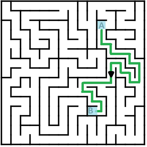
- For this project, what we need to focus on is to have an application, that can accept path commands, and it should create a map on the application.
- The important part here is, to have an interactive map that should have buttons on nodes and edges.
- These buttons shall allow the robot to set its default starting position and ending destination.
- Refer to the below image for a sneak peek of the end results -
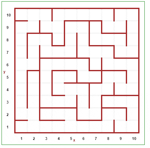
- Each box in the above map is a node. And the path represents the Line that the LFR follows.
- When the (1x, 1y) box is pressed, it is selected as a pick-up point (A), and then it allows us to click another box (3x, 5y) as the drop point (B)
Applications
Line Follower Robot has numerous applications if taken seriously. It is the best method for an automation-required job, where a certain carrier needs to be transported to a nearby location regularly.
- Pick and Drop - Best to use in factories when certain parts and lots are required in a certain location on time.
- Path Guidance for Visitors in Finding the Shortest Path to the Destination.
- Can be used in corporates and domestically for the delivery of amenities throughout the day.
- In the future, travel long distances on autonomous vehicles.

Pick & Drop LFR used in Factory
That's it!! Now that you know the idea behind the King of Maze, you can start making your own!
Head over to (https://www.hackster.io/akshayansinha) now, and check out AWESOME CONTENT on Wireless Devices and use IoT in every possible Embedded Device by yourself!!
CAD, enclosures and custom parts
Credits
Related products


Leave your feedback...