
Led Strip With Ble Device Using Esp32 And Toit

Made by JayeshRajam / Home Automation / Lights / Productivity / Sensors / IoT
About the project
A system to measure how close a BLE device is to the ESP32 board based on its RSSI value and map it on a WS2812B LED strip using Toit.
Project info
Difficulty: Easy
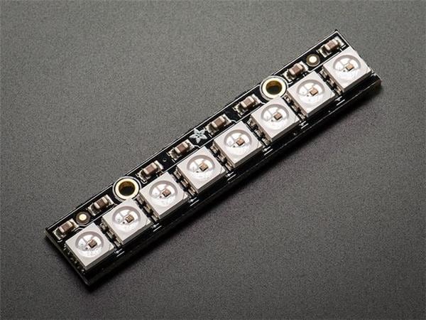
Platforms: NeoPixel, Espressif
Estimated time: 1 hour
License: GNU General Public License, version 3 or later (GPL3+)
Items used in this project
Hardware components

Story
Bluetooth Low Energy is a dynamic low-power, low-cost wireless technology that is designed to work in various industries such as healthcare, fitness, and home entertainment. It is independent of the classic Bluetooth technology and can coexist with other wireless devices. The Received Signal Strength Indicator (RSSI) is a measurement of the power present in a received radio signal and can be used to estimate physical proximity between two devices.
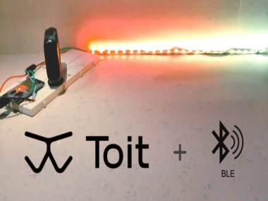
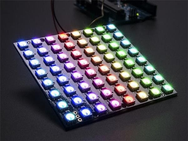
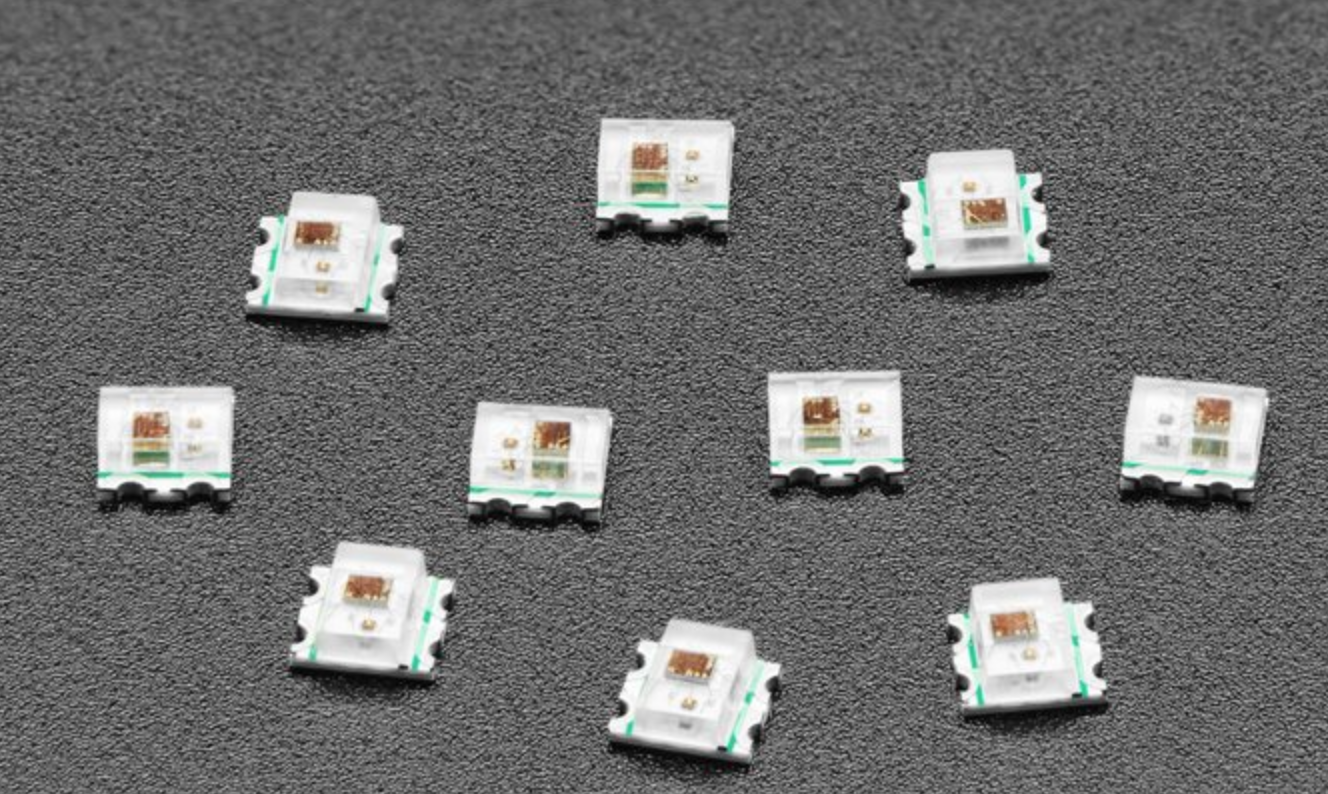
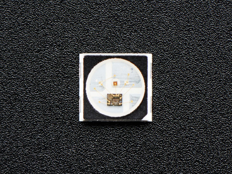
Toit enables extensive use of this BLE technology on any supported ESP32 board with its simple UI and many guiding examples. In this article, we’ll develop a system measuring how close a BLE device is to the ESP32 board using the RSSI Indicator. The measured value will be mapped to show the range on a WS2812B LED strip.
GitHub Link: https://github.com/JayeshRajam/LED-Strip-with-BLE-Device-Toit.git
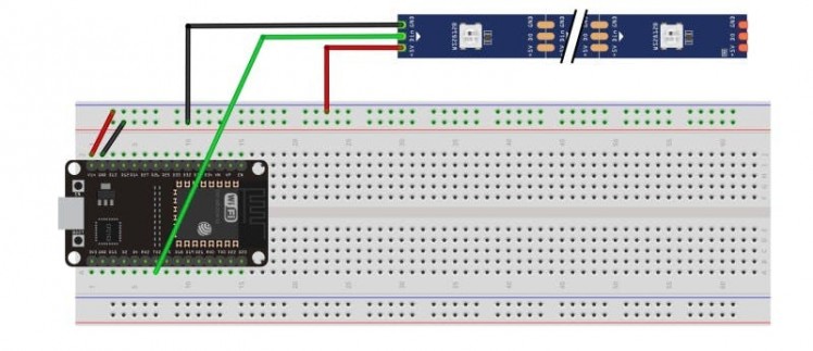
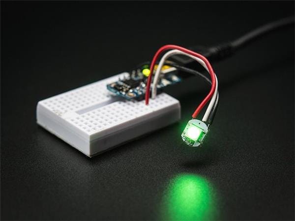
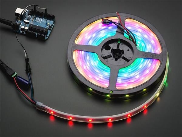
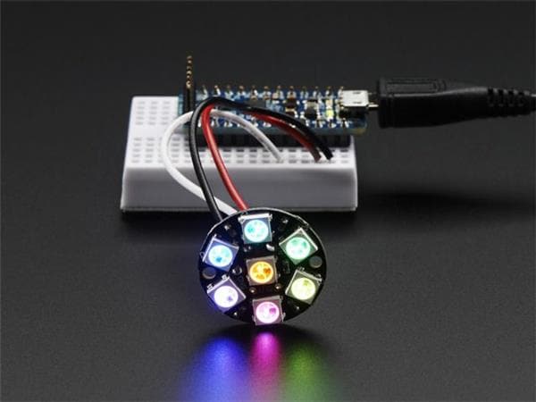
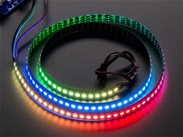
Hardware ConnectionsThe ESP32 board is placed on a breadboard. The WS2812B individually addressable LED strip is powered via an External Power Supply and given signal input from pin 17 of the ESP board. The external BLE device is powered with its visibility setting on, in order to make it discoverable for our ESP board. Here, we used a Mi band as the external BLE device.
To satisfy the power need of the WS2812B LED strip, an external power supply might be needed.
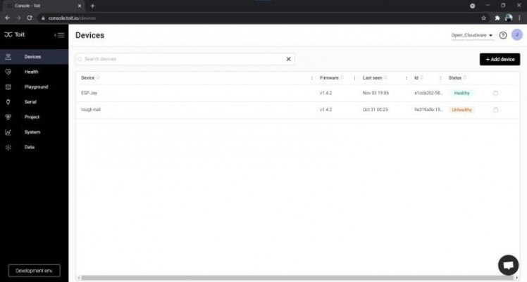
First, set up your Toit account and ESP32 device following Toit’s Quick Start Guide.
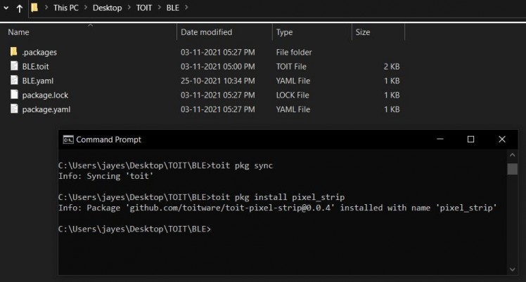
From the Toit CLI, you need to install the pixel_strip library for the WS2812B LED strip provided in the Toit package registry. To do that, in the Toit CLI, open your application directory and run the command
$ toit pkg install pixel_strip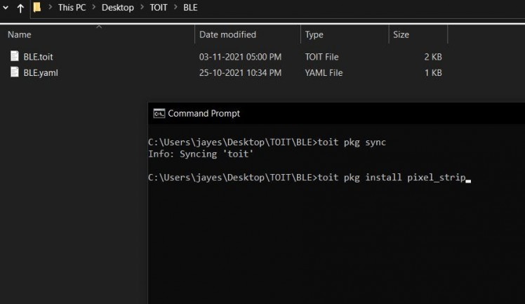
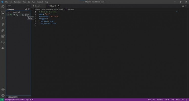
Next up, we’ve used Visual Studio Code to implement and deploy the application.
The program first imports all the necessary libraries including the BLE library.
//Import libraries
import ble
import bitmap show bytemap_zap
import pixel_strip show UartPixelStrip
We declare some necessary global variables and initialize signal pin 17 for our WS2812B LED strip. These values are customizable as per the user’s needs and available inventory.
PIXELS ::= 30  // Number of pixels on the strip.
UL::= -40  // Upper limit of rssi.
LL::= -100   // Lower limit of rssi.
BLE_DEVICE ::= “d3:3e:e3:cd:6b:10”  // Device to watch.
main:
    pixels := UartPixelStrip PIXELS
        –pin=17  // Output pin for UART 2.
    r := ByteArray PIXELS
    g := ByteArray PIXELS
    b := ByteArray PIXELS
Here, PIXELS corresponds to the total number of available LEDs on the WS2812B strip.
Next, we scan for externally available BLE devices from the ESP32 board. Uncomment the printed statement to see the scan results. Note the address of your external BLE device in use.
device := ble.Device.default
    device.scan: | remote_device/ble.RemoteDevice | //Start scanning for devices.
        // print “$remote_device  $remote_device.data.name”
        address := “$remote_device.address“
        if address == BLE_DEVICE:
            rssi := remote_device.rssi
            print “$rssi dBm”
Make sure you enter the correct BLE address in the code. The variable rssi stores the signal strength of only that particular address BLE device you entered before.
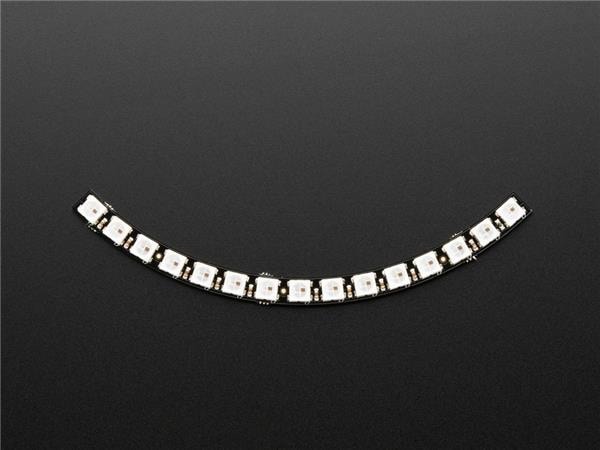
Next, we initialize an array for the WS2812B LED strip, taking into consideration the total number of available LEDs to suit any length strip. The first for loop assigns colours to all available pixels and makes a colour pattern from red to green.
step:= 255 / PIXELS // Step size for colour pattern, 8 in this case.
            r[0] = 0xff // Colormax hexcode.
            g[0] = 0x00 // Colormin hexcode.
            b.fill 0x00
            for i := 1; i < PIXELS; i++: //Initialize led strip’s colour pattern.
                r[i] = r[i–1] – step
                g[i] = g[i–1] + step
The variable PIX stores the number of pixels that should glow for the corresponding rssi value. The second for loop turns all other led pixels off.
// Linear conversion to find number of LEDs to glow as per rssi value
            // range 0 to (PIXELS-1)
            PIX := ((((rssi – LL) * (0 – (PIXELS – 1))) / (LL – UL)) + 0).to_int
            // print PIX
            for j := PIX; j < PIXELS; j++:
                r[j] = 0x00
                g[j] = 0x00
Finally, the optimised array is given as an output to the led strip via the signal pin.
pixels.output r g b
sleep –ms=1Toit’s VS Code extension used here to deploy the application to the ESP board. Open the application’s.toit/.yaml files, click on deploy/run buttons, select your device and the application gets deployed to the board.
See the output on the VS Code’s Toit output (device_name) and Toit logs (device_name) panel.
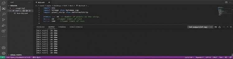
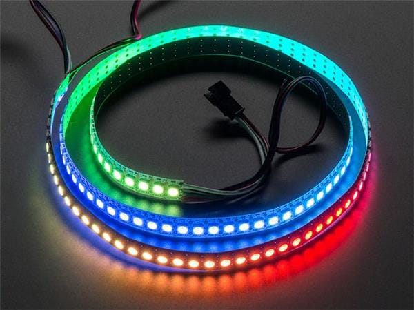
As the Mi band comes close to the ESP board due to strong signal strength, higher RSSI values are obtained. When the device goes far from the board, lower RSSI values are obtained. These RSSI values are correspondingly mapped on the WS2812B LED strip from RED to GREEN along its length.
Application Video:
Code
Credits
Related products


Leave your feedback...