

Led Scanner Atom Matrix Esp32

About the project
In this tutorial we are going to make a Simple LED Scanner using Atom Matrix ESP32.
Project info
Difficulty: Easy
Platforms: Arduino, Visuino, M5Stack
Estimated time: 1 hour
License: GNU General Public License, version 3 or later (GPL3+)
Items used in this project

Story
1 / 2
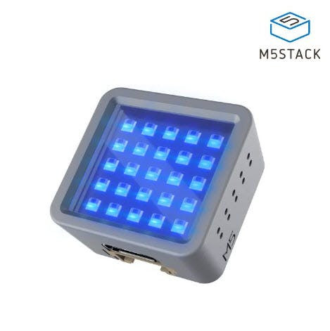
- ATOM Matrix ESP32 More info
- Visuino program: Download Visuino
1 / 2
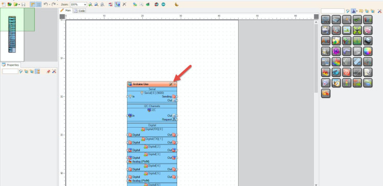
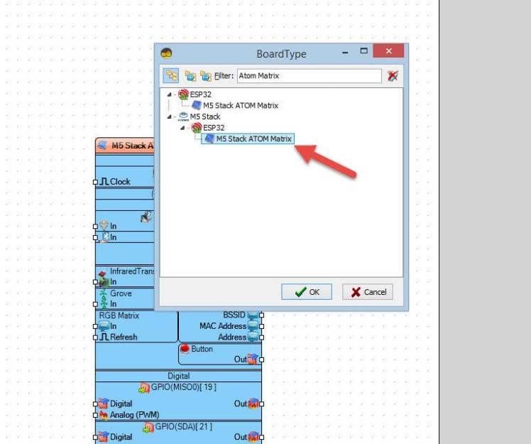
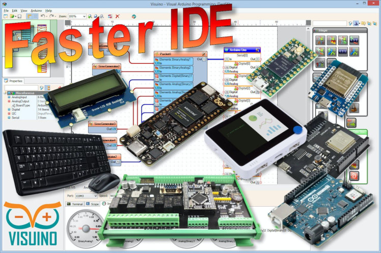
Start Visuino as shown in the first picture Click on the "Tools" button on the Arduino component (Picture 1) in Visuino When the dialog appears, select "Atom Matrix" as shown on Picture 2
Step 3: In Visuino Add Components1 / 6
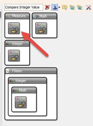
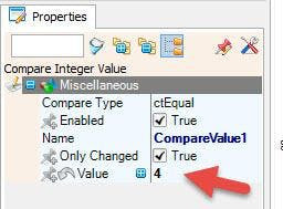
- Add 2X "Compare Integer Value" component
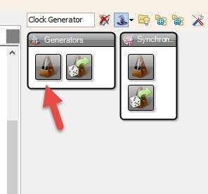
- Add "Clock Generator" component
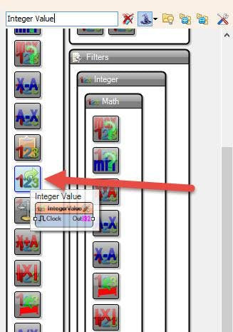
- Add "Integer Value" component
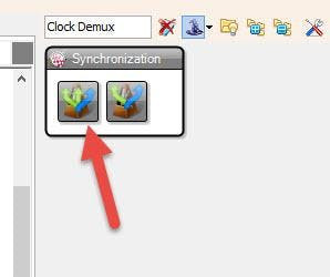
- Add "Clock Demux(Multiple Output channel Switch)" component
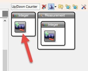
- Add "Up/Down Counter" component
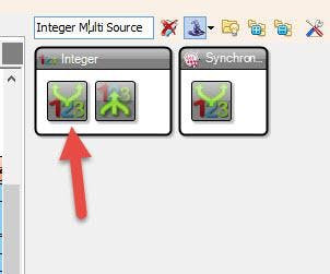
- Add "Integer Multi Source" component
1 / 10

- Select "M5 Stack ATOM Matrix" board in the properties window expand "Modules">"RGB Matrix">"Elements" and click on the 3 dots button
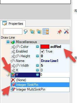
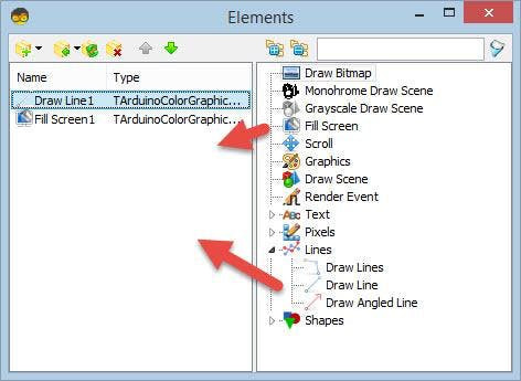
- In the "Elements" window drag "Draw Line" to the left side and in the properties window set "Color" to "aclRed" and Select "Y" & click on the Pin Icon and select "Integer SinkPin"
- In the "Elements" window drag another "Fill Screen" to the left side
- Close the "Elements" window
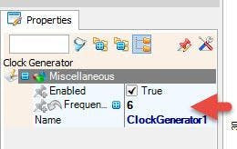
- Select "ClockGenerator1" and in the properties window set "Frequency" to 6
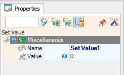
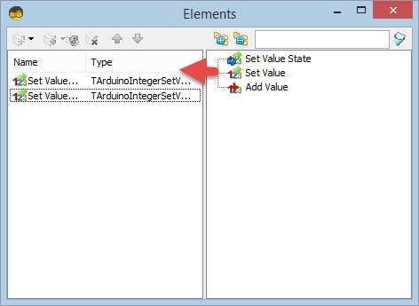
- Double click on the "IntegerValue1" and in the "Elements" window drag "Set Value" to the left side
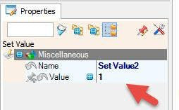
- in the "Elemernts" window drag another "Set Value" to the left side & in the Properties window set "Value" to 1
- Close the "Elements" window
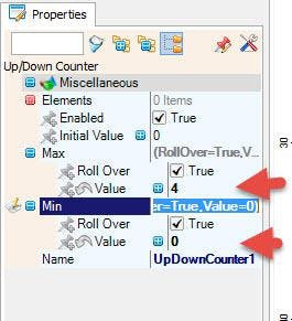
- Select "UpDownCounter1" and in the Properties window set "Max"> "Value" to 4 and "Min">"Value" to 0
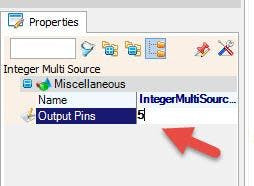
- Select "IntegerMultiSource1" and in the Properties window set "Output Pins" to 5
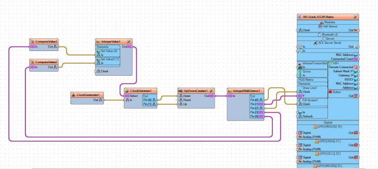
- Connect "CompareValue1" pin [Out] to "IntegerValue1" > "Set Value1" pin [Clock]
- Connect "CompareValue2" pin [Out] to "IntegerValue1" > "Set Value2" pin [Clock]
- Connect "IntegerValue1" pin [Out] to "ClockDemmux1" pin [Select]
- Connect "ClockGenerator1" pin [Out] to "ClockDemmux1" pin [In]
- Connect "ClockDemmux1" pin [0] to "UpDownCounter1" pin [Down]
- Connect "ClockDemmux1" pin [1] to "UpDownCounter1" pin [Up]
- Connect "UpDownCounter1" pin [Out] to "IntegerMultiSource1" pin [In]
- Connect "IntegerMultiSource1" pin [0] to to "M5 Stack ATOM Matrix" > "RGB Matrix" > "Fill Screen1" pin[Clock]
- Connect "IntegerMultiSource1" pin [1] to to "M5 Stack ATOM Matrix" > "RGB Matrix" > "Draw Line1" pin[Y]
- Connect "IntegerMultiSource1" pin [2] to to "M5 Stack ATOM Matrix" > "RGB Matrix" > "Draw Line1" pin[Clock]
- Connect "IntegerMultiSource1" pin [3] to to "CompareValue1" pin[Clock]
- Connect "IntegerMultiSource1" pin [4] to to "CompareValue2" pin[Clock]
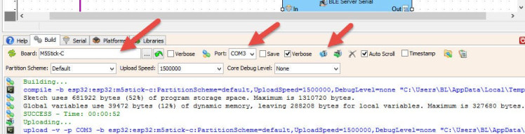
In Visuino, at the bottom click on the "Build" Tab, make sure the correct port is selected, then click on the "Compile/Build and Upload" button.
Step 7: PlayIf you power the ATOM Matrix module The Display will start to show the Red colored Scanning effect.
Congratulations! You have completed your project with Visuino. Also attached is the Visuino project, that I created for this tutorial, you can download it and open it in Visuino: https://www.visuino.eu
Schematics, diagrams and documents
Code
Credits
Related products


Leave your feedback...