

Intuitive And Smart - My Nxp Cup 2020 Racer

Made by Fast_and_Genius / 3D Printing / Automotive / Communication / Environmental Sensing / Vehicles
About the project
Follow me through the development and build process of my autonomous model car pursuing a spot on the podium at this year's NXP Cup.
Project info
Difficulty: Difficult
Estimated time: 5 months
License: GNU General Public License, version 3 or later (GPL3+)
Items used in this project
Hardware components

View all
Software apps and online services
Story
NXP Cup
The NXP Cup let students get creative and design autonomous race cars to compete with each other.
The cup has 5 different challenges whereby only the timed race is mandatory:
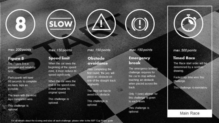
For more information about the cup visit https://community.nxp.com/groups/tfc-emea.
About me
I am bachelor student of automotive computer science at the University of Applied Sciences Landshut. This year is going to be the second year in a row I participate the NXP Cup. When I got in touch with the cup first time in 2018, the existing team at my university just won the NXP Cup EMEA, which let me to step into big footprints. I started to develop an all new car from scratch for 2019 since the cup's rules have been changed and a new chassis was available.
The result was this, not really pretty and not really fast, but stable driving car which taught me a lot of basics and experience necessary for the next NXP Cup:
Cup 2020
Due to a study abroad semester, I was able to begin developing the new car 2 weeks before qualification.
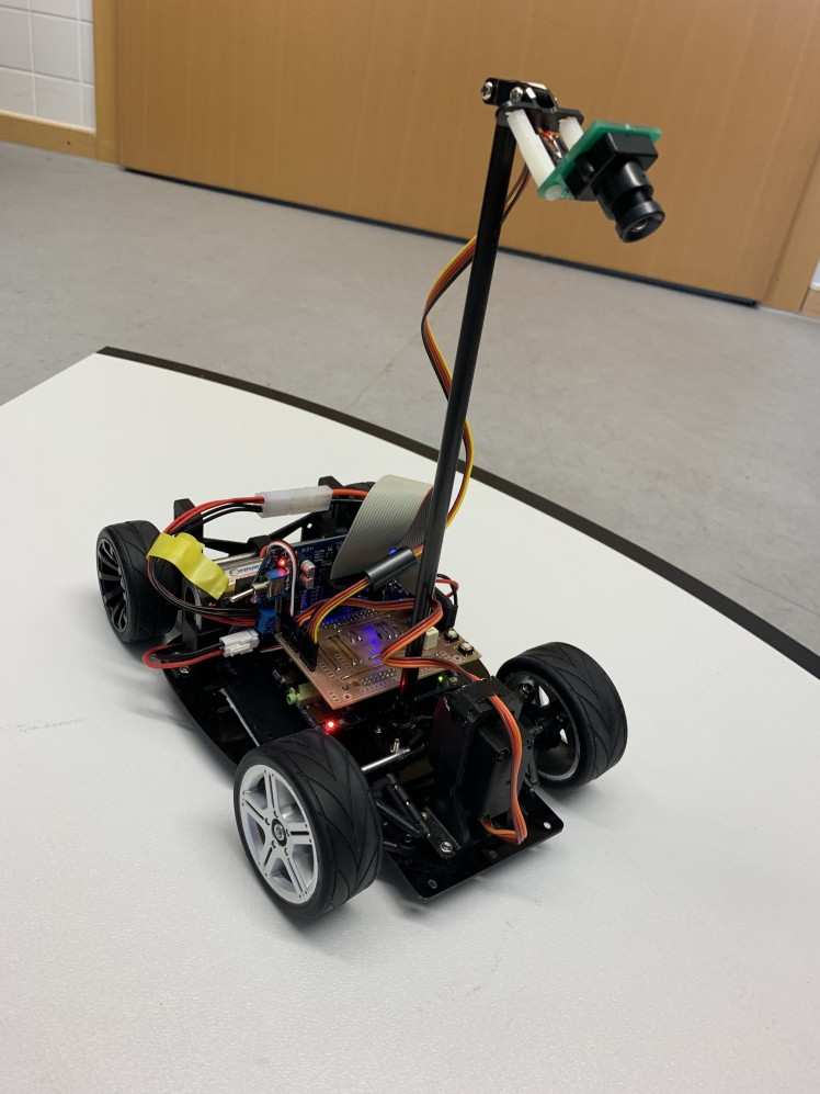
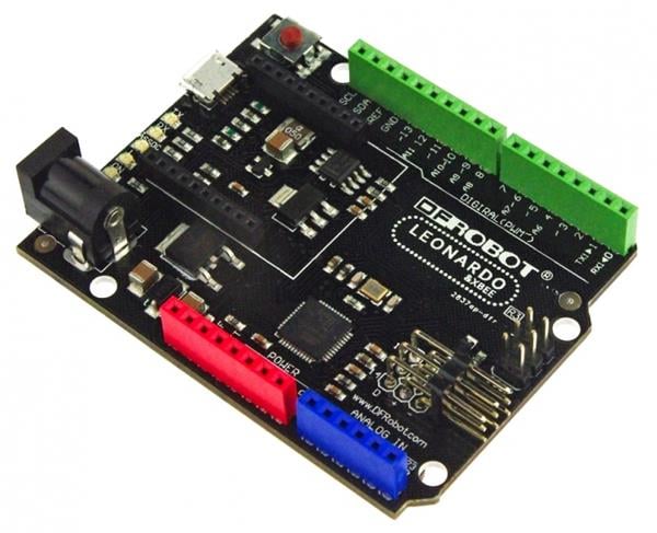
Using the new DFRobot ROB0165 chassis, the NXP FRDM-K66f and the Pixy2 camera, I was able to build a car within a week, which was able to drive on the road, but not fast at all. This was mainly caused by the steering algorithm.
But then... "2020 NXP CUP EMEA postponed due to coronavirus". This e-mail gave me the chance to realize all my plans in mind for this year's cup:
- Custom Mainboard
- Pixy2 USB connection
- Display
- 3D printed parts
- Revise steering algorithm
- Ultrasonic sensors
Planning
MCU
Even as a one-man team right now, I have some regulations by my supervising professor at my university. He is also supporting the project with developments by master students of his classes.
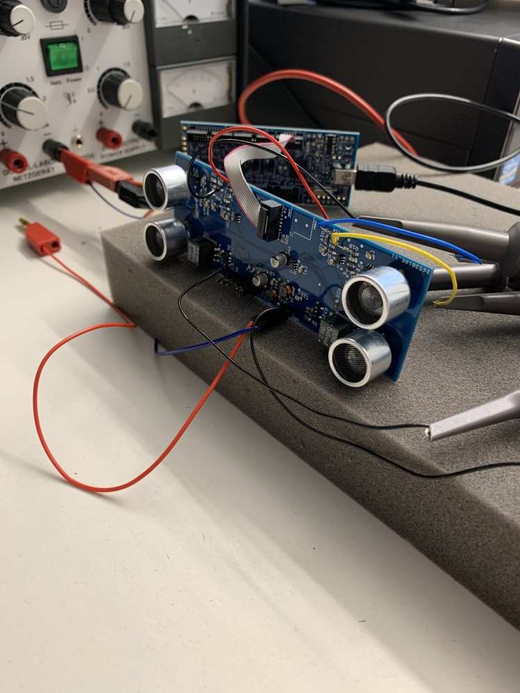
A resulting component is the ultrasonic board, which hardware was designed and revised in master student projects. My task is to program the board and include it to the car’s ecosystem.
Despite I worked with the FRDM-K66f board so far, I decided to switch to another MCU. The LPC54616 has been used for the ultrasonic board. While programming it, I got comfortable with the controller and thought it might be a good idea to only have one type of MCU being used for the car. That simplifies the project structure and reduces code variety. The ultrasonic board was developed to be interfaced with CAN, which leads to a CAN compatible infrastructure for the car.
NXP offers an evaluation board for the LPC54628 called OM13098, which basically just differs to the LPC54616 in peripheral count. As long as I don’t have a custom PCB with this MCU onboard, the evaluation board allows me to build up a prototype system.
PCB
To maximize efficiency and minimize spatial use I want to design a custom PCB including all necessary connections and components to have one mainboard controlling all interfaced slaves. The hardware layout should fit on the car’s chassis and make it as clean as possible.
Pixy2
This year’s NXP Cup rule adaptions allow matrix cameras and recommend the Pixy2 camera. Like I mentioned earlier, I the camera was already working fine with good results. But haven’t been happy with the interface protocol and its results. So I decided to use USB to connect the Pixy2 camera to my MCU board.
Display
Already planned for the car from 2019, I wanted to use a display for drive mode settings and status output. The OLED graphical display can be interfaced via I2C and has 128x64 pixels.
Miscellaneous
All other components are supposed to be connected directly to the main MCU. This includes the steering servo, motors and input devices like rotary encoder and buttons.
The following graphic gives an overview about the interface infrastructure planned for this year’s car:
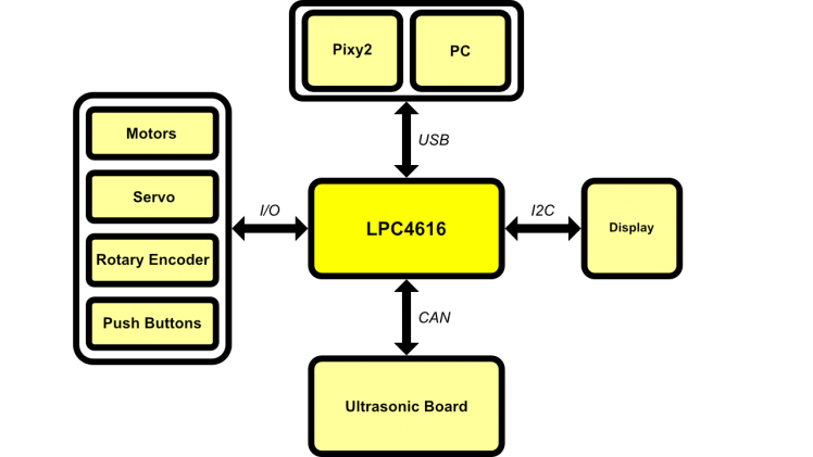
Software
One important thing for me was to make easy-to-understand and hierarchical software. My favorite programming language is C which needs less system resources than C++ and suits better in embedded systems. Object Oriented Programming is a nice feature but for my opinion, C offers me all the features I need for this project.
Instead of using a baremetal project, I switched to Amazon FreeRTOS. It not only offers me easy handling of all the different bus interfaces but also let me learn more about operating system programming.
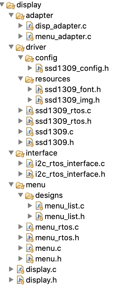
Hierarchical software help me to switch or edit components quick and fail safe. The I2C interface I use for the display is a good example: I use the SDK I2C driver, enclose it with RTOS necessary code and adapt that to the display driver. Like this, the display driver can be used with any interface, even with baremetal.
Development
PCB
At first I started with the schematic of the mainboard since the process for PCB development takes a lot of time. Later changes can still be applied to the schematic before the PCB is in production. Important components which have to be on the PCB are:
- Power supply (3.3V / 5V / 7.2V)
- Power supply for servo (DC-DC Converter)
- USB-Host for Pixy2 connection
- USB-Device for computer connection (planned for future)
- CAN Transceiver
- Display
- Rotary Encoder
- Push Buttons
- Extension Connector
Due to COVID-19 the PCB has not passed the schematic planning right now. I don't have access to the design tools. It is planned to be fully equipped on the car for NXP Cup, though.
Pixy2 - USB
Programming the Pixy2 USB interface was intense work, but a fun part. The code of Pixy2 is open source but not well documented so that I had to reverse engineer the whole code.
At the very beginning I used a Mac build in USB probe tool to figure out which communication protocol and path the camera uses. Like you can see on the following image, the camera simply uses two bulk endpoints - one for data IN and one for data OUT - in a vendor specific class. Interface #0 is not further implemented in the Pixy2 USB driver code.
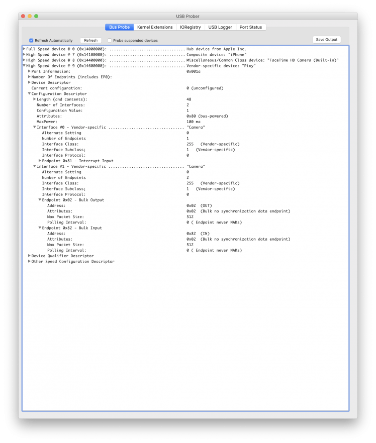
Since the USB class is vendor specific, I had to write my own generic class driver which interfaces the bulk endpoints. The MCUXpresso SDK example projects really helped me along there, because at this point I had no idea how to implement such a driver. I basically copied all the code from "usb_hid_generic.c/.h" in the "usb_host_hid_generic_freertos" example and changed the endpoints to bulk. I also had to change some code to let the driver attach the right PID and VID. Running the code with a camera plugged into the evaluation board returned a successful connection.
More time consuming was to analyze the camera's communication protocol. Next to the open source code of the camera, there is also some code to connect it to a Linux running system like a Raspberry Pi. To figure out what I need to send to the camera to receive something, I build parts of the Linux project on the computer and debugged the send / receive buffer while being connected to a physical camera.
The result was a "remote init" instruction with following structure:
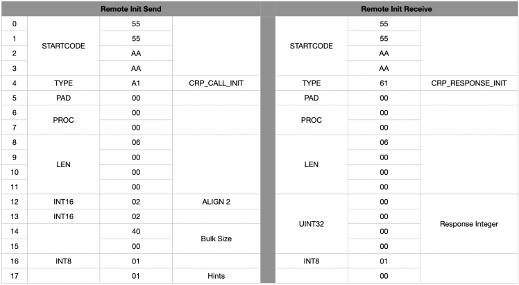
This also worked for my own generic USB driver. At this point the USB connection to the camera was already established and working. But there was a lot more work to do.
To understand the protocol I just read all the camera's parser code - called chirp - backwards. It took me some days to really understand every feature and how I can access it with my custom code. Just using the chirp code and run it on my MCU was no option, because it is programmed in C++ and not nice to include at all.
One feature of Pixy2 is sending a continuous data stream via USB. This stream contains program related data and is used by the corresponding computer software PixyMon v2 to display all the data with high data rate. While implementing this feature I recognized a problem with the SDK USB Stack I used:
Every Pixy2 packet is sent in 64 byte blocks. Unfortunately, if the camera transmits stream data the block size can be different. The problem was that the USB Stack appends data in a 1 byte align which results in a wrong alignment of receiving data. To solve this, I edit the USB stack so that it aligns the received data by 64 byte.
It took some more days to finalize my code and build it in a hierarchical way like I wanted to have it.
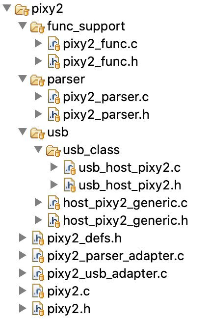
Finally, having a structured code which covers all my needs, it is possible to access the camera in an easy way. As an example the following function which is part of "pixy2_func" controls the RGB led mounted under the camera's lens:
- uint32_t pixy2_func_led_set(pixy2_t *pixy2, uint8_t red, uint8_t green, uint8_t blue) {
- uint32_t status;
- pixy2_lock(pixy2);
- pixy2_chirp_enumerate(pixy2, "led_setRGB");
- pixy2_chirp_add_arg(pixy2, CRP_INT8, red, 1);
- pixy2_chirp_add_arg(pixy2, CRP_INT8, green, 1);
- pixy2_chirp_add_arg(pixy2, CRP_INT8, blue, 1);
- pixy2_chirp_send(pixy2);
- status = pixy2->data.resp;
- pixy2_unlock(pixy2);
- return status;
- }
HMI
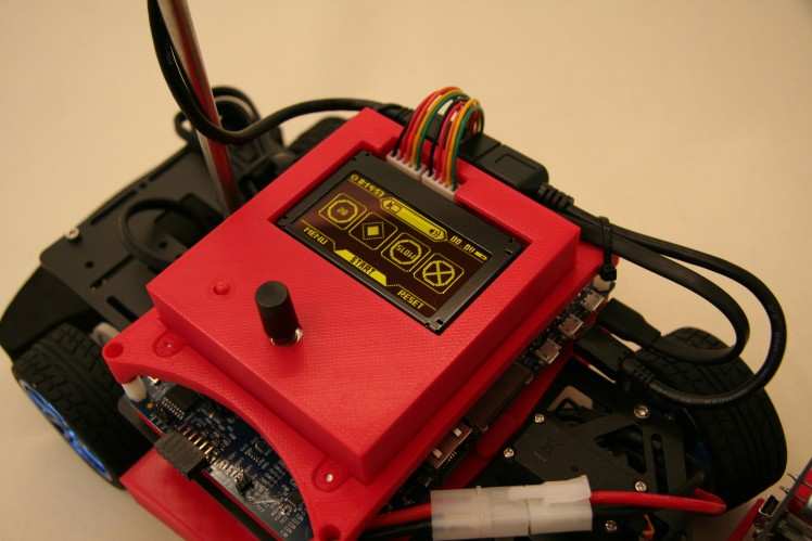
Like described earlier, a display was already planned for the last car in 2019. Therefore I had a code base and foreknowledge how to implement the display. Desired was to use the display as part of the human machine interface in interaction with push-buttons and a rotary encoder. Changing parameter and receiving error notifications have always been complex for me and the earlier NXP Cup teams of my university. To achieve intuitive control and easy implementation I spend some time to make a graphical and operating concept. Based on the planned PCB Layout the display content has to be self-describing and easy-to-use.
The Vishay OLED display I used has an onboard SSD1309 driver, so I implemented a basic driver which supports simple command and graphic functions:
- void ssd1309_init(ssd1309_t *obj);
- void ssd1309_fill(ssd1309_t *obj, ssd1309_color_t color);
- void ssd1309_set_pixel(ssd1309_t *obj, uint8_t x, uint8_t y, ssd1309_color_t color);
- void ssd1309_draw_rect(ssd1309_t *obj, uint8_t x1, uint8_t y1, uint8_t x2, uint8_t y2, bool fill, ssd1309_color_t color);
- void ssd1309_write_char(ssd1309_t *obj, char chr, ssd1309_font_t font, bool bg, ssd1309_color_t color);
- void ssd1309_write_str(ssd1309_t *obj, char *str, ssd1309_font_t font, bool bg, ssd1309_color_t color);
- void ssd1309_draw_img(ssd1309_t *obj, uint8_t x, uint8_t y, ssd1309_img_t img, ssd1309_color_t color);
- void ssd1309_update(ssd1309_t *obj);
- void ssd1309_send(ssd1309_t *obj, ssd1309_data_t d_type, uint8_t *data, uint32_t size) __attribute__((weak));
- static inline void ssd1309_set_pos(ssd1309_t *obj, uint8_t x, uint8_t y) {
- obj->pos.x = x;
- obj->pos.y = y;
- }
This library also uses an adapter to connect to the underlaying bus driver. Since the display supports several communication interfaces it could be switched to another interface than I2C quick.
An important higher level part of the display driver is the menu. I programmed a library, which adapts to the SSD1309 driver and is able to have different designs like shown below.
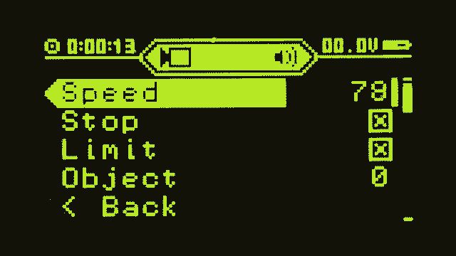
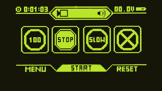
Both views use the same menu control code with different design codes, which makes it easy to extend the user content to specific needs. The code base is still small and fast that it is capable of refreshing the display's image buffer with 30fps without intercepting other important tasks.
To complete the user interaction there is also a controlling unit necessary, which reads and debounce input devices like push-buttons and manages the content on the display.
Miscellaneous
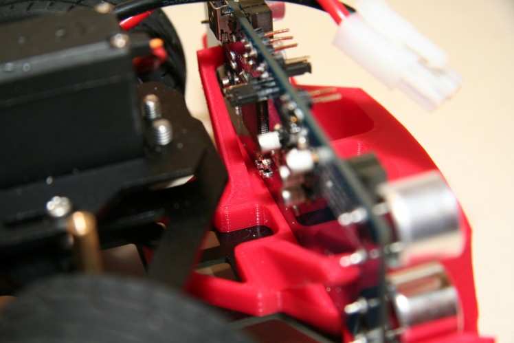
For test purposes I decided to make a simple PCB with line grid to adapt power supply, servo and motors. The servo power is provided by an BEC module, which is also connected to the PCB. A 5V regulator is necessary to power the USB Host on the evaluation board.
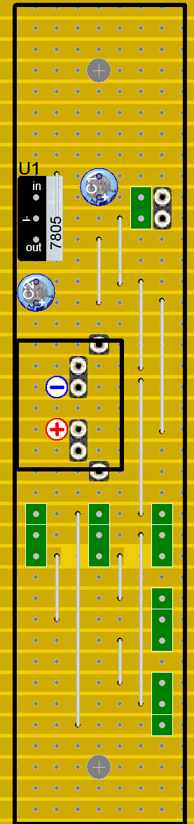
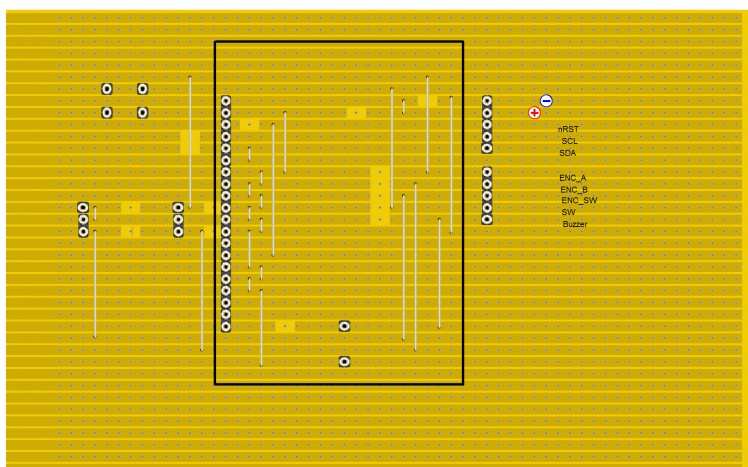
Another PCB with line grid contains the display, rotary encoder, push button and a buzzer. This simply arranges the components in right place like they will be on the custom mainboard PCB.
3D Printed Parts
The DFRobot ROB0165 chassis offers not only a lot of space due to the two stacked plates but also many drill holes for extensions. I used these attachment options to design useful parts which can be 3D printed.
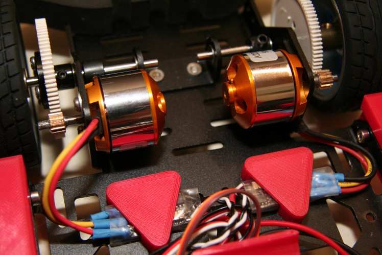
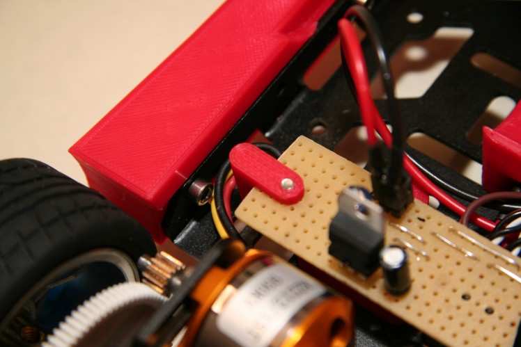
Motor-Controller mount
Simple triangles hold the motor controllers in place.
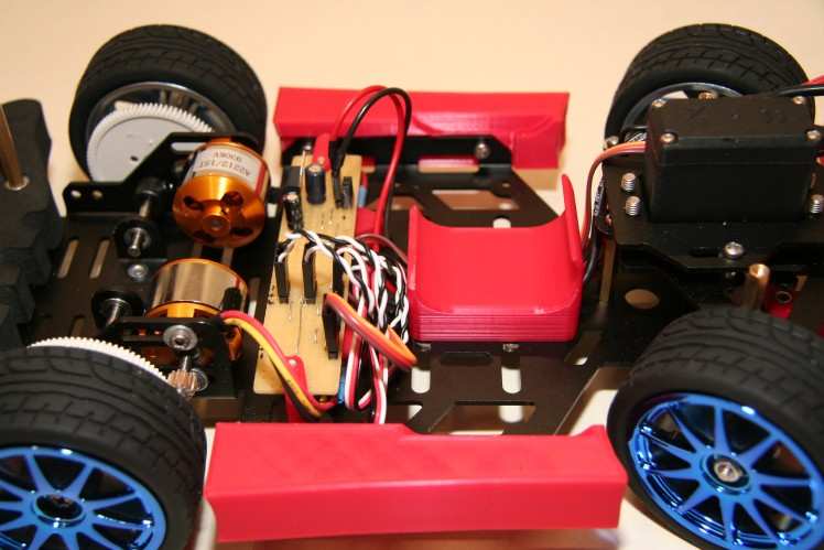
Battery mount
The 7.2V battery is held by the rocker panels and an additional mount in the middle of the chassis.
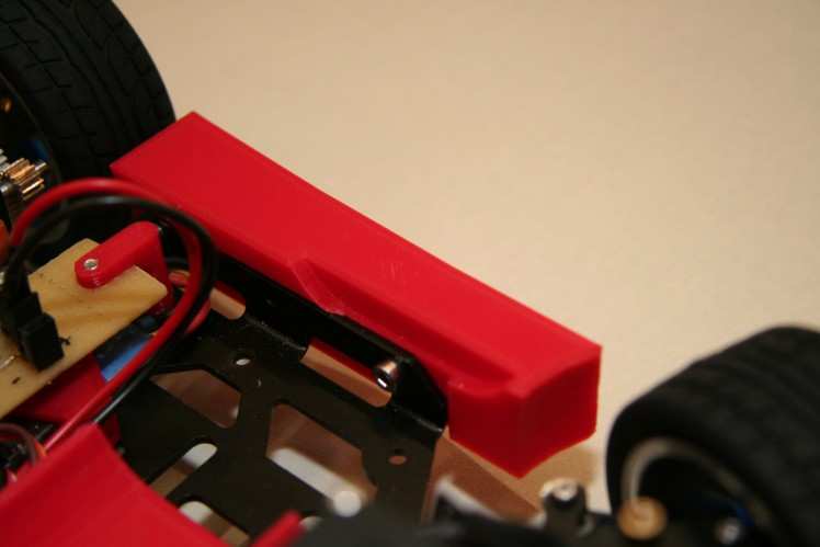
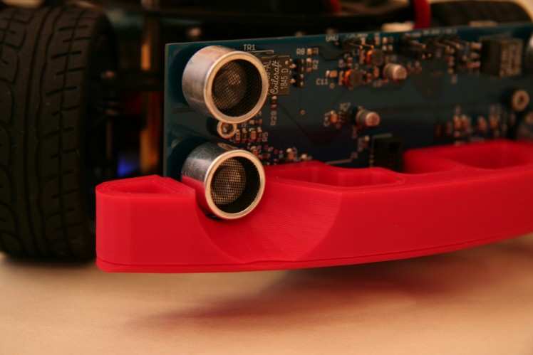
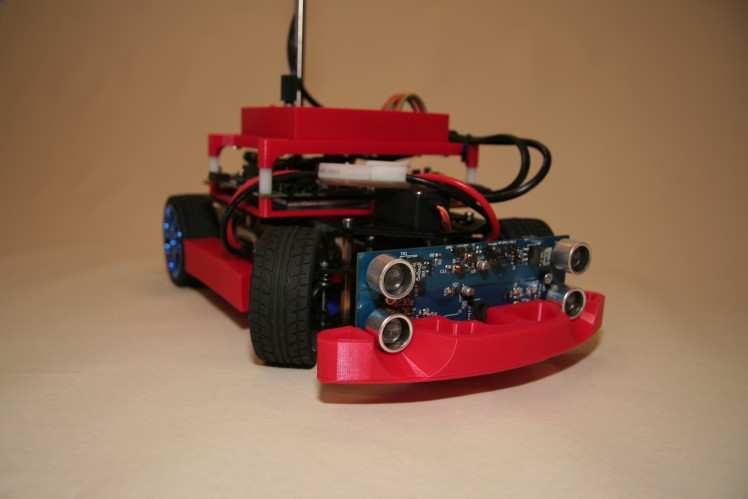
Ultrasonic mount + Front-Bumper
A small mount is holding the ultrasonic board in place while the sensors are protected by a custom front bumper replacing the original foam bumper.
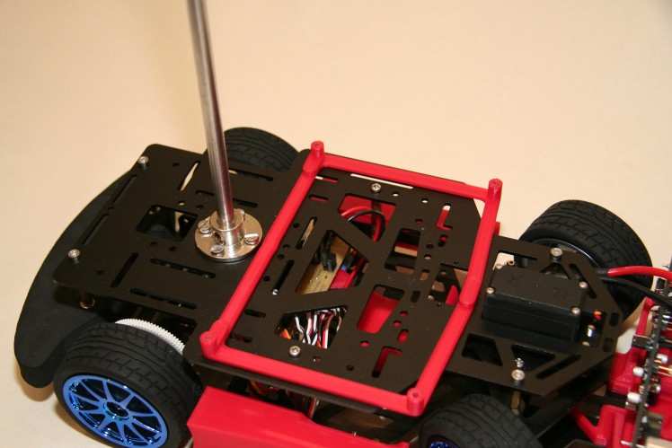
Evaluation-Board mount
Holding the evaluation board in place this mount is mandatory for a stable operation.
HMI mount
For proper control while using the evaluation board as mainboard.
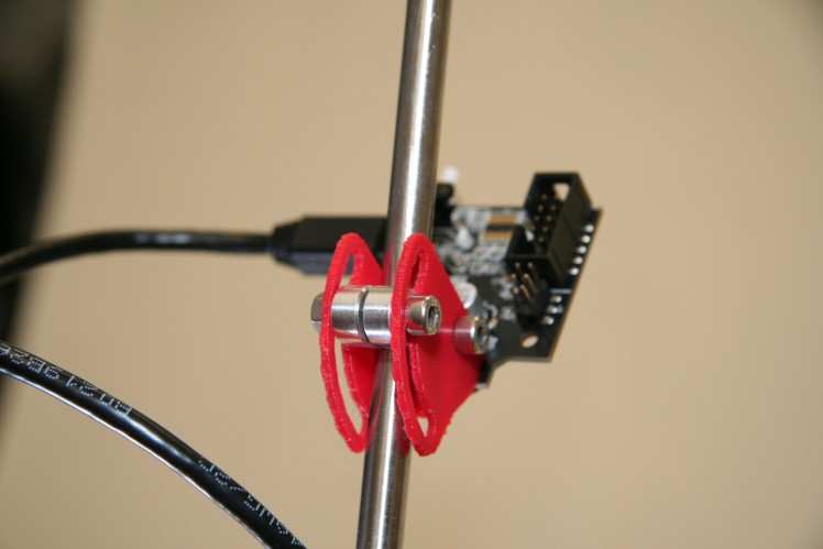
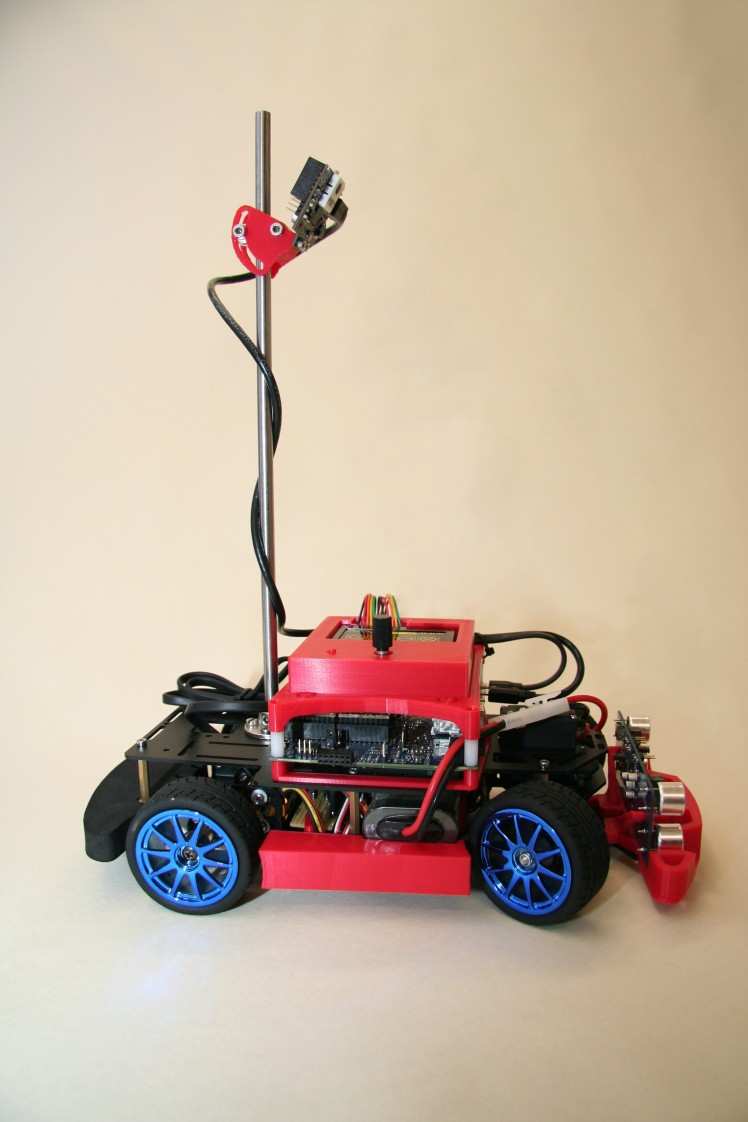
Pixy mount
Complementing the original chassis camera mount this little Pixy2 mount even allows precise angle adjustment.
Power-PCB mount
As long as the evaluation board is used there is need of a custom power-distributing PCB, which needs to be held in place.
Current State
Upcoming
- Most important for the NXP Cup is the revise of the steering algorithm. This is going to be the next step.
- The custom PCB mainboard needs to be routed and send to fabrication.
- To be able to accomplish the object avoidance and emergency brake challenges, the ultrasonic board needs to be connected to the mainboard via CAN.
Schematics, diagrams and documents
CAD, enclosures and custom parts
Credits
Related products


Leave your feedback...