
Infrared Obstacle Avoidance Sensor With Visuino

Made by Ron / Environmental Sensing / Robotics / Sensors
About the project
Connect Infrared Obstacle Avoidance Sensor to Arduino Nano and program it to detect obstacles - Quick and Easy!
Project info
Difficulty: Easy
Estimated time: 1 hour
License: GNU General Public License, version 3 or later (GPL3+)
Items used in this project

Software apps and online services
Story
Infrared Obstacle Avoidance sensors are cheap, small sensors often used in robots, and Arduino project to detect objects near the sensor.
The Infrared sensors work by sending an infrared light with some frequency, and then detecting if some of the light has reflected back to the sensor. The most common ones have a digital output indicating if object has been detected. Many of them have the option to be enabled or disabled.
In this tutorial, I will show you how easy it is to connect and use such sensor with Arduino.
Some of the sensors have a brief false detection when they are enabled. In the tutorial, I will also show you how you can suppress this false detection with Visuino.
Step 1: Components
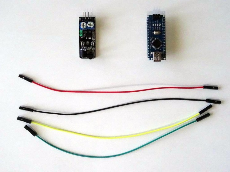
- One Arduino compatible board (I use Arduino Nano, because I have one, but any other will be just fine)
- One Infrared Obstacle Avoidance Sensor module I got from this cheap 37 sensors set
- 4 Female-Female jumper wires
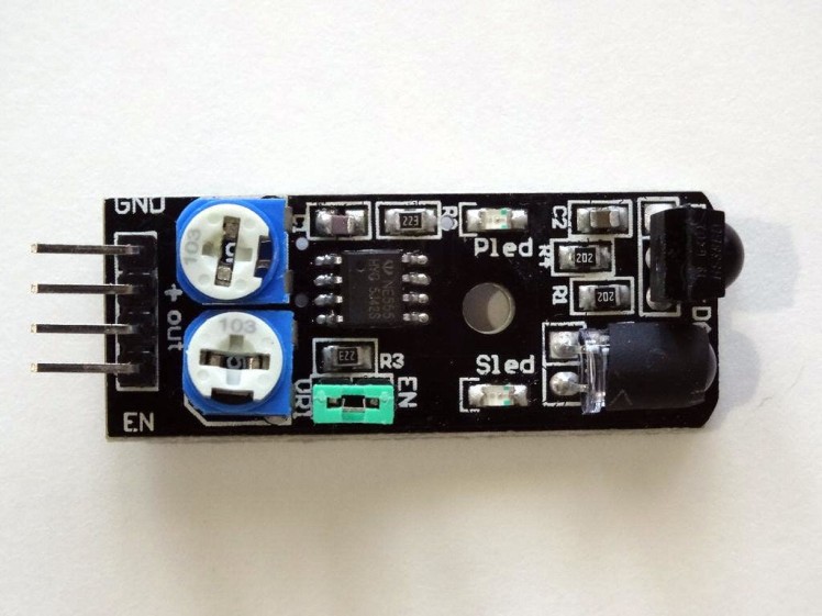
The Obstacle Avoidance Sensors usually come in two types - with 3 and 4 pins. The 3 pin version does not have the ability to be enabled/disabled. The 4 pin version has optional Enable pin. Here I am describing the 4 pin version that I have. The information should also be relevant to other versions of the sensor.
The Infrared Obstacle Avoidance Sensor has Power, Ground, Signal, and Enable pins.There are also 2 potentiometers, and one jumper on the board (See the Picture).The top potentiometer on the picture is used to adjust how sensitive the sensor is. You can use it to adjust the distance from the object at which the sensor detects it.
The bottom potentiometer on the picture usually should not be changed. It controls the frequency of the infrared signal, and is preset with a good setting. You may need to use it if there is infrared interference with other infrared sources, but otherwise, avoid changing it.
If the Enable pin of the board is not connected, the jumper should be placed on the board as seen on the picture. The jumper permanently enables the board, and if the jumper is placed the Enable pin can't be used to enable/disable the board.
If you want to use the Enable pin, you have to remove the jumper.
Step 3: Connect the Sensor to Arduino
1 / 4 • Picture 1

Picture 1

Picture 2

Picture 3

Picture 4
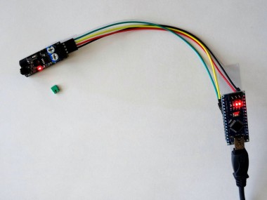
- Connect Ground (Black wire), Power (Red wire), and Signal (Yellow wire) to the Infrared Obstacle Avoidance Sensor Module (Picture 1)
- Connect the other end of the Ground wire (Black wire) to the Ground pin of the Arduino board (Picture 2)
- Connect the other end of the Power wire (Red wire) to the 5V power pin of the Arduino board (Picture 2)
- Connect the other end of the Signal wire (Yellow wire) to the Digital pin 2 of the Arduino board (Picture 3)
- Picture 4 shows where are the Ground, 5V Power, and Digital 2 pins of the Arduino Nano
1 / 2 • Picture 1

Picture 1

Picture 2
To start programming the Arduino, you will need to have the Arduino IDE installed from here: http://www.arduino.cc/ .
Make sure that you install 1.6.7 or higher, otherwise this Tutorial will not work!
The Visuino: https://www.visuino.com also needs to be installed.
- Click on the "Tools" button on the Arduino component (Picture 1) in Visuino
- When the dialog appears, select Arduino Nano as shown in Picture 2
Connect the "Out" pin of the Digital[ 2 ] channel of the Arduino component to the "Digital" input pin of the Digital[ 13 ] channel of the Arduino component as shown on the picture
Step 6: Generate, Compile, and Upload the Arduino code
1 / 2 • Picture 1

Picture 1

Picture 2
- In Visuino, Press F9 or click on the button shown on Picture 1 to generate the Arduino code, and open the Arduino IDE
- In the Arduino IDE, click on the Upload button, to compile and upload the code (Picture 2)
1 / 3 • Picture 1

Picture 1

Picture 2

Picture 3
On Picture 1 you can see the completed and running project. The LED on Pin 13 is On. If you put object at front of the sensor the LED on Pin 13 will turn Off (Picture 2)
On Picture 3 you can see the complete Visuino diagram.
Step 8: Connect the Enable line of the sensor to Arduino
1 / 3 • Picture 1

Picture 1

Picture 2

Picture 3
- Remove the Enable Jumper from the Obstacle Avoidance Sensor Module (Picture 1)
- Connect Enable (Green wire) to the Infrared Obstacle Avoidance Sensor Module (Picture 1)
- Connect the other end of the Enable wire (Green wire) to the Digital pin 3 of the Arduino board (Picture 2)
- Picture 3 shows with Red Arrow where is the Digital pin 3 of the Arduino Nano
1 / 3 • Picture 1

Picture 1

Picture 2

Picture 3
To test the Enable functionality of the sensor we can use a Pulse generator and set it to enable and disable the sensor periodically.
- Type "puls" in the Filter box of the Component Toolbox then select the "Pulse Generator" component (Picture 1), and drop it in the design area
- In the Object Inspector, set the value of the "Frequency" property of the PulseGenerator1 component to 0.2 (Picture 2)
- Connect the "Out" pin of the PulseGenerator1 component to the "Digital" input pin of the Digital[ 3 ] channel of the Arduino component(Picture 3)
Press F9 to Generate the code, and open the Arduino IDE, then compile and Upload the Sketch as you did in Step 6.
The project will work, but as you can also see in the second part of the Video, the sensor (At least the type, that I have) has a brief false detection when it gets enabled. This may be fine in some cases, but usually is not desirable, so move to the next step to see how you can avoid the problem.
Step 10: Avoid flase detection: In Visuino: Add and connect Infrared(IR) Obstacle Avoidance Sensor component
1 / 3 • Picture 1

Picture 1

Picture 2

Picture 3
- Start with a new project, and select Arduino Nano as board type as you did in Step 4
- Type "infra" in the Filter box of the Component Toolbox then select the "Infrared(IR) Obstacle Avoidance Sensor" component (Picture 1), and drop it in the design area
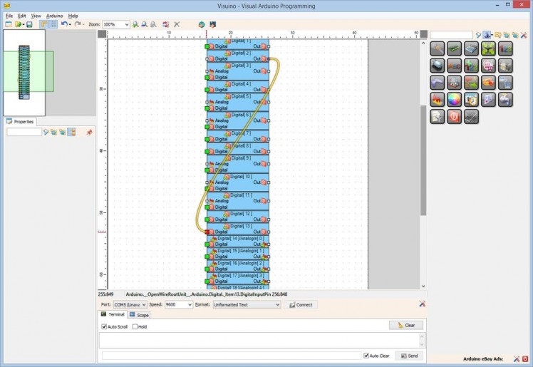
- Connect the "Out" pin of the Digital[ 2 ] channel of the Arduino component to the "In" pin of the ObstacleAvoidance1 component (Picture 2)
- Connect the "Out" pin of the ObstacleAvoidance1 component to the "Digital" input pin of the Digital[ 13 ] channel of the Arduino component(Picture 3)
1 / 5 • Picture 1

Picture 1

Picture 2

Picture 3

Picture 4

Picture 5
- Type "pul" in the Filter box of the Component Toolbox then select the "Pulse Generator" component (Picture 1), and drop it in the design area
- In the Object Inspector, set the value of the "Frequency" property of the PulseGenerator1 component to 0.2 (Picture 2)
- Connect the "Out" pin of the PulseGenerator1 component to the "Enable" input pin of the ObstacleAvoidance1 component (Picture 3)
- Connect the "Enable" output pin of the ObstacleAvoidance1 component to the "Digital" input pin of the Digital[ 3 ] channel of the Arduino component (Picture 4)
- You can optionally specify a different delay for ignoring false detection when enabling the Sensor, by setting a different value for the EnableDelay property of the ObstacleAvoidance1 component in the Object Inspector (Picture 5)
1 / 2 • Picture 1

Picture 1

Picture 2
On Picture 1 you can see the completed and powered up project, and the sensor with the disconnected Enable Jumper.
In the last part of the video you can see that when the sensor is enabled it has a brief false detection, but that detection is not shown in the LED on Pin 13. The "Infrared(IR) Obstacle Avoidance Sensor" component in Visuino suppresses the false detection when enabling the sensor.
Congratulations! You have mastered using Infrared Obstacle Avoidance Sensor module with Arduino, and Visuino.
On Picture 2 you can see the complete Visuino diagram.
Also attached are the Visuino projects, that I created for this Tutorial. You can download and open them in Visuino: https://www.visuino.com
Credits
Related products


Leave your feedback...