
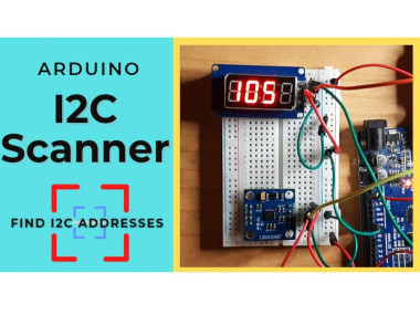
I2c Scanner - How To Find I2c Addresses On Arduino

Made by Ron / Communication / Displays / Environmental Sensing / Notifications / IoT
About the project
In this tutorial we are going to make an I2C Scanner that will display an I2C Adress of the connected sensor or a module.
Project info
Difficulty: Easy
Estimated time: 1 hour
License: GNU General Public License, version 3 or later (GPL3+)
Items used in this project
Hardware components

Story
1 / 5

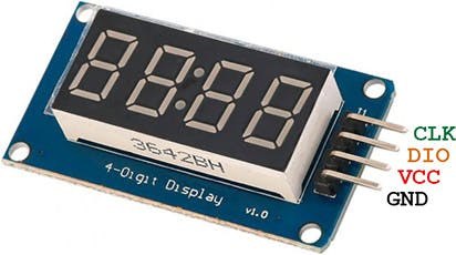
- TM1637 LED Display
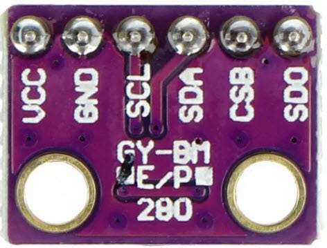
- Some I2C sensor for testing
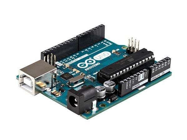
- Arduino UNO (or any other Arduino)
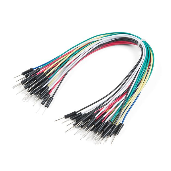
- Jumper wires
- Breadboard
- Visuino program: Download Visuino

Thank you PCBWay for supporting this tutorial and helping users learn more about electronics.
What I like about the PCBWay is that you can get 10 boards for approximately $5 which is really cost effective for professional made boards, not to mention how much time you save!
Go check them out here. They also offer a lot of other stuff in case you might need it like assembly, 3D printing, CNC machining and a lot more.
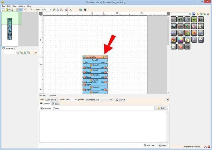
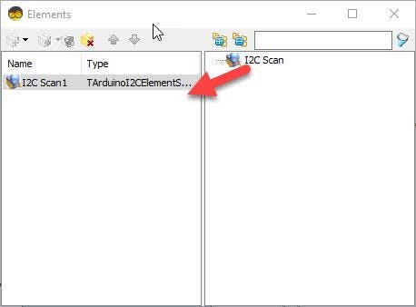
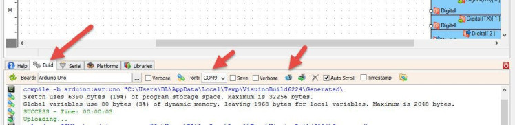
Note: Make sure to disconnect the power from Arduino, when you replace the I2C MODULE/SENSOR 1 / 2 Start Visuino as shown in the first picture Click on the "Tools" button on the Arduino component (Picture 1) in Visuino When the dialog appears, select "Arduino UNO" as shown on Picture 2 1 / 5 In Visuino, at the bottom click on the "Build" Tab, make sure the correct port is selected, then click on the "Compile/Build and Upload" button. If you power the Arduino module, The LED Display will show the I2C address of the connected sensor or module. Congratulations! You have completed your project with Visuino. Also attached is the Visuino project, that I created for this tutorial, you can download it and open it in Visuino: https://www.visuino.eu
Step 3: The Circuit


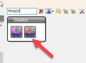
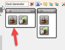
Step 6: In Visuino Connect Components
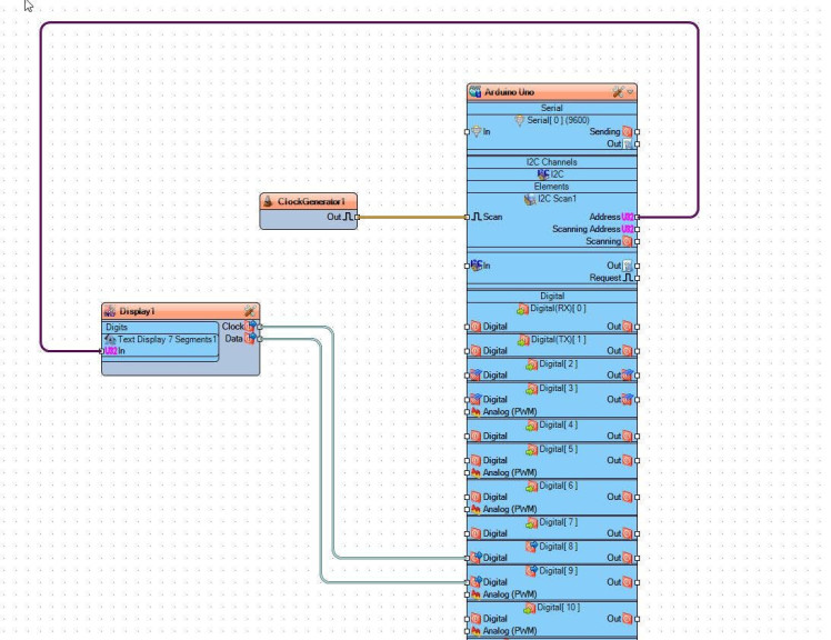
Step 7: Generate, Compile, and Upload the Arduino Code
Schematics, diagrams and documents
Code
Credits
Related products


Leave your feedback...