
I2c Communication Between Two Arduino Boards With Visuino

About the project
Use I2C communication to connect 2 Arduino boards and implement I2C Ultrasonic Ranger with Visuino.
Project info
Difficulty: Easy
Estimated time: 1 hour
License: GNU General Public License, version 3 or later (GPL3+)
Items used in this project

Software apps and online services
Story
The Arduino and most other microcontroller boards, and microcomputers are usually equipped with at least one I2C communication channel. The I2C is typically used to connect sensors to the microcontroller, and the microcontroller to operate as a Master for the I2C bus. Most microcontrollers however can be configured as Slave I2C devices. This allows for the I2C bus to be used for communication between the controllers.
I have posted a number of Tutorials on how to connect I2C devices to Arduino and ESP8266 controllers. Multiple people have asked me for example of Arduino to Arduino I2C communication. Finally I have found time to prepare this Tutorial.
Here I will show you how you can connect 2 Arduino Nano boards, and configure one of them to control the second one over I2C bus. The I2C Slave controller will measure distance with Ultrasonic Ranger, and when asked will send the distance to the Master controller over the I2C bus.
Step 1: Components

- 2 Arduino compatible board (I used 2 Arduino Nanos, because I have them, but any other will be just fine)
- One Ultrasonic Ranger Sensor Module - I used US-015, but HC-SR04, or very much any other will also work
- 4 Female-Female jumper wires
1 / 2 • Picture 1

Picture 1

Picture 2
We need to connect Ground and the 2 I2C wires between the Arduino boards. We will start with the Master I2C Arduino board:
- Connect Female-Female Ground jumper wire (Black Wire) to the Ground pin of the Master Arduino Nano board (Picture 1)
- Connect Female-Female SCL jumper wire (Yellow Wire) to the SCL/Analog pin 5 of the Master Arduino Nano board (Picture 1)
- Connect Female-Female SDA jumper wire (Green Wire) to the SDA/Analog pin 4 of the Master Arduino Nano board (Picture 1)
- Picture 2 shows where are the Ground, SDA/Analog pin 4, and SCL/Analog pin 5, pins of the Master Arduino Nano
1 / 2 • Picture 1

Picture 1

Picture 2
We need to connect Ground and the 2 I2C wires to the Slave I2C Arduino board:
- Connect the other end of the Ground wire (Black Wire) to the Ground pin of the Slave Arduino Nano board (Picture 1)
- Connect the other end of the SCL wire (Yellow Wire) to the SCL/Analog pin 5 of the Slave Arduino Nano board (Picture 1)
- Connect the other end of the SDA wire (Green Wire) to the SDA/Analog pin 4 of the Slave Arduino Nano board (Picture 1)
- Picture 2 shows where are the Ground, SDA/Analog pin 4, and SCL/Analog pin 5, pins of the Slave Arduino Nano
1 / 4 • Picture 1

Picture 1

Picture 2

Picture 3

Picture 4
- Connect Ground(Black wire), Power(Red wire), Trigger(Gray wire), and Echo(Purple wire) to the Ultrasonic Ranger Sensor Module (Picture 1)
- Connect the other end of the Power wire(Red wire) to the 5V power pin of the Slave Arduino Nano board(Picture 2)
- Connect the other end of the Ground wire(Black wire) to Ground pin of the Slave Arduino Nano board(Picture 3)
- Connect the other end of the Trigger wire(Gray wire) to Digital pin 2 of the Slave Arduino Nano board(Picture 3)
- Connect the other end of the Echo wire(Purple wire) to Digital pin 3 of the Slave Arduino Nano board(Picture 3)
- Picture 4 shows in Red where are the Ground, 5V Power, Digital 2, and Digital 3 pins of the Slave Arduino Nano(In Blue are shown the connections made in the previous step)
1 / 2 • Picture 1

Picture 1

Picture 2
Since the Arduino Nano has only one Serial port, and it is needed to program the Arduino, you will need to program the Arduino Nano before the GPS is connected.
To start programming the Arduino, you will need to have the Arduino IDE installed from here: http://www.arduino.cc/ .
Make sure that you install 1.6.7 or higher, otherwise this Tutorial will not work!
The Visuino: https://www.visuino.com also needs to be installed.
- Start Visuino as shown in the first picture
- Click on the "Tools" button on the Arduino component (Picture 1) in Visuino
- When the dialog appears, select "Arduino Nano" as shown in Picture 2
1 / 2 • Picture 1

Picture 1

Picture 2
- In the Object Inspector expand the "I2C" property (Picture 1)
- In the Object Inspector set the value of the "Address" sub property to "22" (Picture 1) - You can set another number. Just make sure the Master Arduino project uses the same number so the 2 devices will be able to talk
- In the Object Inspector set the value of the "Is Slave" sub property to "True" (Picture 2)
1 / 3 • Picture 1

Picture 1

Picture 2

Picture 3
We need to send a raw analog value over the I2C. The simplest option is to packet it as a structure with one floating point element:
- Type "struct" in the Filter box of the Component Toolbox then select the "Make Structure" component (Picture 1), and drop it in the design area
- Connect the "Out" output pin of the MakeStructure1 component to the "In" input pin of the "I2C" channels of the Arduino component (Picture 1)
- Connect the "Request" output pin of the "I2C" channel of the Arduino component to the "Clock" input pin of the MakeStructure1 component (Picture 2)
1 / 3 • Picture 1

Picture 1

Picture 2

Picture 3
- Click on the "Tools" button of the MakeStructure1 component (Picture 1) to open the "Elements" editor (Picture 2)
- In the "Elements" editor select the “Analog” element on the right, and then clickon the "" button on the left (Picture 2) to add Analog element (Picture 3)
- Close the "Elements" editor.
1 / 4 • Picture 1

Picture 1

Picture 2

Picture 3

Picture 4
- Type "sonic" in the Filter box of the Component Toolbox then select the "Ultrasonic Ranger(Ping)" component (Picture 1), and drop it in the design area
- Connect the "Ping(Trigger)" pin of the UltrasonicRanger1 component (Picture 3) to the "Digital" input pin of the Digital[ 2 ] channel of the Arduino component (Picture 2)
- Connect the "Out" pin of the Digital[ 3 ] channel of the Arduino component to the "Echo" input pin of the UltrasonicRanger1 component (Picture 3)
- Connect the "Out" output pin of the UltrasonicRanger1 component to the "In" input pin of the "Elements.Analog1" of the MakeStructure1 component (Picture 4)
1 / 3 • Picture 1

Picture 1

Picture 2

Picture 3
Picture 1 shows the complete Visuino diagram of the Slave I2C Arduino project.
- Connect the Slave Arduino Nano (The one with the Ultrasonic Ranger attached) to the computer
- In Visuino, Press F9 or click on the button shown on Picture 2 to generate the Arduino code, and open the Arduino IDE
- In the Arduino IDE, click on the Upload button, to compile and upload the code (Picture 3)
1 / 3 • Picture 1

Picture 1

Picture 2

Picture 3
We need send I2C Requests to the Slave Arduino specifying the device address and asking for 4 bytes of data (floating point value. For this we need to add I2C Device component:
- Start a new project, and select Arduino Nano board as you did in Step 5.
- Type "i2c" in the Filter box of the Component Toolbox then select the "I2C Device" component (Picture 1), and drop it in the design area
- In the Object Inspector set the "Address" property of the I2CDevice1 component to "22" (Picture 2) - this address should be the same as the one set in the Slave Arduino project
- Connect the "Out" output pin of the I2CDevice1 component to the "In" input pin of the "I2C" channel of the Arduino component (Picture 3)
1 / 3 • Picture 1

Picture 1

Picture 2

Picture 3
Next we need to add a request element to the I2C Device component and specify the size of the request:
- Click on the "Tools" button of the I2CDevice1 (Picture 1) to open the "Elements" editor (Picture 2)
- In the "Elements" editor select the “Request” element on the right, and then clickon the "" button on the left (Picture 2) to add I2C Request element (Picture 3)
- In the Object Inspector set the value of the "Size" property to "4" (Picture 3) - This will specify 4 bytes (floating point value is 32 bits = 4 bytes) to be requested from the I2C bus
- Close the "Elements" editor
1 / 4 • Picture 1

Picture 1

Picture 2

Picture 3

Picture 4
The I2C data will arrive from the Slave Arduino as floating point binary data.We need to decode it properly. For this we need a “Split Structure” component with 1 “Analog” elements in it.
- Type "struct" in the Filter box of the Component Toolbox then select the "Split Structure" component (Picture 1), and drop it in the design area
- Click on the "Tools" button of the SplitStructure1 component (Picture 2) to open the Elements editor (Picture 3)
- In the "Elements" editor select the “Analog” element, and then click on the "+" button (Picture 3) to add Analog element (Picture 4)
- Close the "Elements" editor
1 / 2 • Picture 1

Picture 1

Picture 2
- Connect the "Out" output pin of the "Operations.Request1" element of the I2CDevice1 component to the "In" input pin of the SplitStructure1 component (Picture 1)
- Connect the "Out" output pin of the "Elements.Analog1" element of the SplitStructure1 component to the "In" input pin of the "Serial[ 0 ]" channel of the Arduino component (Picture 2)
1 / 2 • Picture 1

Picture 1

Picture 2
Next we need to specify when the request for data will be sent. In my case I decided to request the data once a second. For this I used a Clock Generator with its default frequency of one clock per second:
- Type "clock" in the Filter box of the Component Toolbox then select the "Clock Generator" component (Picture 1), and drop it in the design area
- Connect the "Out" pin of the ClockGenerator1 component to the "Clock" input pin of the I2CDevice1 component (Picture 2)
1 / 3 • Picture 1

Picture 1

Picture 2

Picture 3
Picture 1 shows the complete Visuino diagram of the Master I2C Arduino project.
- Connect the Master Arduino Nano to the computer
- In Visuino, Press F9 or click on the button shown on Picture 2 to generate the Arduino code, and open the Arduino IDE
- In the Arduino IDE, click on the Upload button, to compile and upload the code (Picture 3)
1 / 5 • Picture 1

Picture 1

Picture 2

Picture 3

Picture 4

Picture 5
Congratulations! You have completed the project.
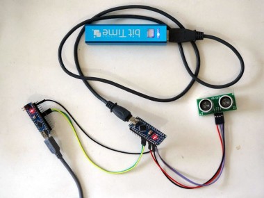
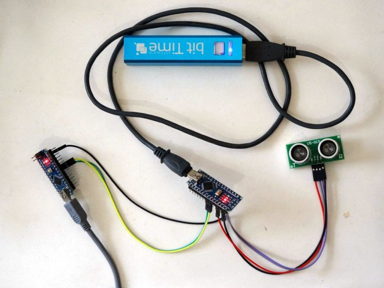
Picture 1 shows the connected and powered up project. In my case I used a USB Power Bank to power the Slave controller so it is visible that only the Master controller is connected with USB to the computer, but you can power both Arduinos with USB cable from the computer.
If you connect with a Serial Terminal you will see the distance measured with the Ultrasonic Ranger printed once a second (Picture 2)
You can connect with Visuino too by selecting the serial port, and clicking on the Connect button (Picture 3). You should see the distance printed once a second (Picture 4), and if you switch to the Scope view, you will see the distance plotted over time (Picture 5)
Also attached are the Visuino projects, that I created for this Tutorial. You can download and open them in Visuino: https://www.visuino.com
Credits
Related products


Leave your feedback...