
Hsl Jacket
About the project
Control lights on your arms with the zipper on your jacket! It uses HSL color, or Hue Saturation Lightness, an intuitive way to pick colors.
Project info
Difficulty: Moderate
Platforms: Arduino, Maxim Integrated
Estimated time: 4 hours
License: GNU General Public License, version 3 or later (GPL3+)
Items used in this project
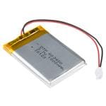
Hardware components

Story
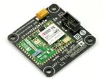
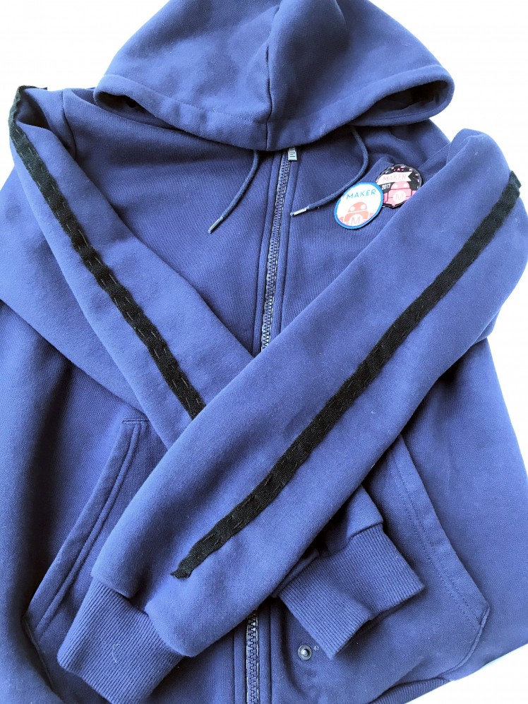
This project adds lighting to an ordinary jacket, lighting you up at night, making you more visible to vehicles when biking, hiking, or doing any nighttime activity. The lights are controlled by the zipper on the jacket, which acts like a potentiometer. The whole thing is controlled by the MAX32620FTHR.
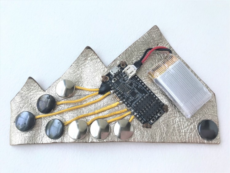
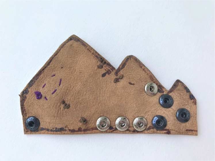
Step 1: Sew the MAX32620FTHR
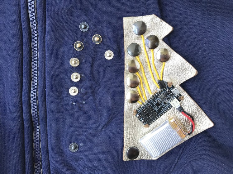
If you want to be able to wash your jacket, it's best to have all the electronics on a separate piece of fabric and connect it to the parts on the jacket with buttons or clips. If you don't feel the need to be able to wash the jacket or aren't worried about the electronics getting soapy water on them, then you don't have to have them on a separate piece of fabric.
 Front Side
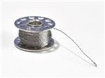
Since I'm using a scrap piece of leather, it's harder to sew, so I soldered wire to the connections instead. If you are using fabric that's easy to sew, feel free to use the conductive thread to make the connections. Just make sure that the conductive thread isn't touching any other connections or thread.
I had a button/rivet kit from some previous projects so I used that. If your fabric is easy to sew, you can use some sew on fasteners to connect the board to the jacket. The schematic is in the GitHub repo here.
 Back Side
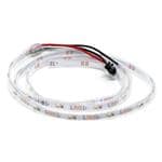
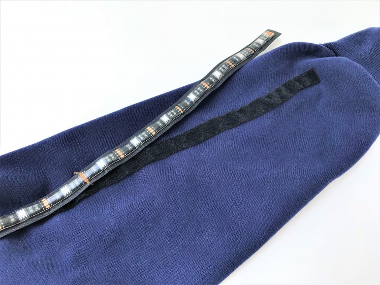
Step 2: Sew the LED Strip
My LED strip came in a 1 meter strip, so I cut it in half to fit it on the arms. I found that 0.5m is just about a perfect length for most jacket arms. If you don't want the LEDs to be detachable, you don't need the Velcro or the headers and can sew the strip directly onto the jacket. Otherwise, solder some male headers onto the LED strip.
;; Velcro on arms
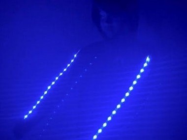
After soldering the headers on, attach the LED strip onto the hook side of the Velcro. The Velcro I used was a thinner, more flexible type. The LED strip had adhesive on the back but it wasn't very strong, so I used thread in addition to the adhesive. After doing so, I sewed the other side onto the jacket on the arms. Now you should have LED strips on the arms of the jacket.
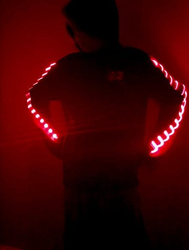
 Finished arms
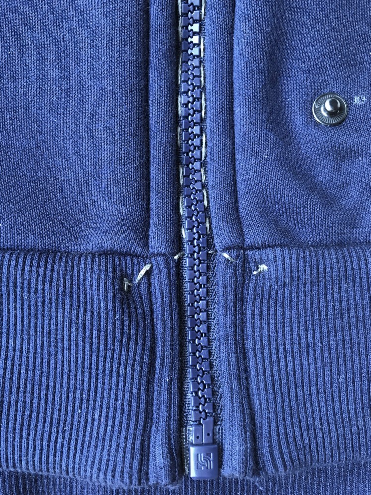
Step 3: Make the Zipper Potentiometer
The zipper potentiometer was made following this. Check it out for the full instructions. To sum it up, sew a length of conductive thread along the zipper as close as possible on both sides. The goal is to have 2 rows of conductive thread bridged by the zipper. To test your connections, I used a multimeter in conductivity mode. Then you can measure the resistance to see if it works.
The Instructables has a resistor in the schematic which I added on the separate piece of fabric with the other electronics on it.
Step 4: Connect Everything Together
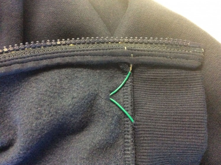
As my sewing skills aren't the best, I just used normal wire soldered onto the female headers to make the connections, but if you are better at sewing then definitely use the conductive thread. It's more flexible and you don't have all that slack. I used some normal thread and glue to secure the header to the jacket. You should now have 4 wires which you can connect to the controls. Test them by attaching a battery to the wires, + to +, - to R, then G, then B. If the LED's light up, great! If not, check your connections.
 front side header
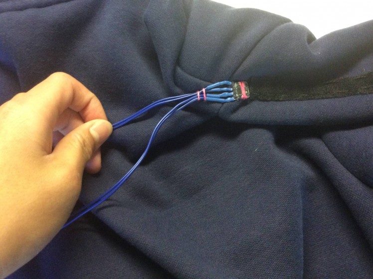
Both arms are wired together in parallel, and since the electronics were on the left side, I wired the left LED strip to the electronics. The zipper works the same way, except instead of headers, I looped the exposed end of the wire into the pad to make a secure connection, then threaded the wire through the bottom of the jacket to the left pocket.
 zipper wires going into pocket
Then I soldered the ends of the wire to the metal buttons. If you are using conductive thread, you can use sew-on buttons or just loop the thread a couple times around the rivet thing. If the button has some kind of coating, it may be helpful to sand or file it off before making a connection.
Great! Now the hardware should be done!
Step 5: Program the MAX32620FTHR
While the hardware part of this project is complete, I am still figuring out things in the software. I am trying to develop this in stages, maybe something simple first, like just red, green and blue, then moving on to maybe some color mixing, then the final HSL picker.
Right now, the current code in the GitHub repo is a blink sketch that will cycle through red, green, and blue. It works, but does not use the zipper functionality. I am working on that next.
To program the MAX32620FTHR, I used the Arduino IDE because that's what I'm familiar with. The code I publish will also be written in the Arduino IDE syntax. Since the MAX32620FTHR also supports other development environments, you can update the code to the correct syntax for your preferred development environment. Instructions for all the supported environments are here.
The software will be available on the GitHub repo here as it comes out. A description will also be there. If you have any suggestions about software, then feel free to let me know.
Issues/Improvements
As I am still working on the software, I'll just go over some existing hardware issues here. Since the MAX32620FTHR is a 3.3v board, it cannot power 5v LEDs at full brightness. If you can find 3.3v RGB LED strips, feel free to use those. If you can't but still want a brighter light, you may have to use an external power source with a LED driver/MOSFET/relay. Also, the potentiometer seems to not be too stable, so the code may need some calibration depending on how you made your jacket. The pull tag on the zipper might also need to be covered as that might have something to do with the instability. Further tests will need to be done. If you have any suggestions, please let me know.
Schematics, diagrams and documents
Code
Credits
Related products


Leave your feedback...