
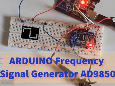
How To Use Arduino Dds Frequency Signal Generator Ad9850

Made by Ron / Communication / Displays / Sensors
About the project
In this Tutorial we will learn how to make a Frequency Signal Generator using a AD9850 module and Arduino.
Project info
Difficulty: Easy
Platforms: Arduino, SparkFun, Visuino
Estimated time: 1 hour
License: GNU General Public License, version 3 or later (GPL3+)
Items used in this project
Hardware components

Story
In this Tutorial we will learn how to make a Frequency Signal Generator using a AD9850 module and Arduino.
Watch the Video!
Note: I managed to get frequency up to +50MHz but the signal quality gets worse with the higher frequencies.
Step 1: What You Will Need
1 / 4
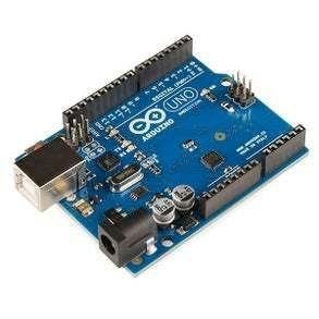
- Arduino Uno or any other Arduino board
- AD9850 (DDS Synthesizer) More Info
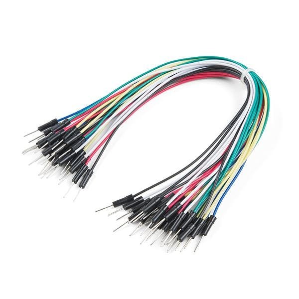
- Jumper wires
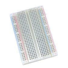
- Breadboard
- Visuino software: Download here
ad9850.pdf
Step 2: Output Response
1 / 2

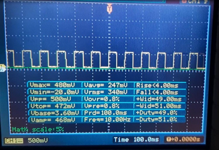
You can see the output results for the frequency 10Hz
- First picture is Scope connected to SQ Wave 1 pin
- First picture is Scope connected to Sine Wave 1 pin
Step 3: The Circuit
1 / 3
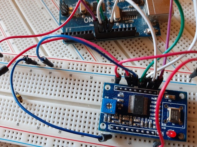

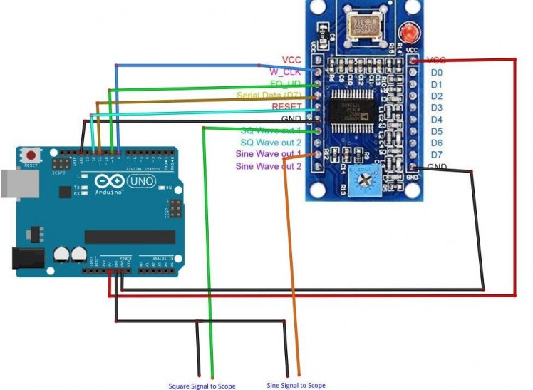
- Connect "AD9850" module pin Serial "W_CLK" to Arduino Digital pin 8
- Connect "AD9850" module pin Serial "FQ_UD" to Arduino Digital pin 9
- Connect "AD9850" module pin Serial "Serial Data" to Arduino Digital pin 11
- Connect "AD9850" module pin Serial "Reset" to Arduino Digital pin 10
- Connect "AD9850" module pin VCC to Arduino pin 5V
- Connect "AD9850" module pin GND (On both sides) to Arduino pin GND
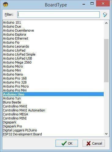
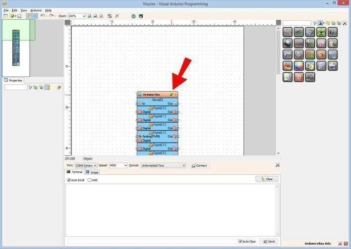
Step 4: Start Visuino, and Select the Arduino UNO Board Type
1 / 2
The Visuino: https://www.visuino.eu also needs to be installed. Download Free version or register for a Free Trial.
Start Visuino as shown in the first picture Click on the "Tools" button on the Arduino component (Picture 1) in Visuino When the dialog appears, select "Arduino UNO" as shown on Picture 2
Step 5: In Visuino Add, Set & Connect Components
1 / 4
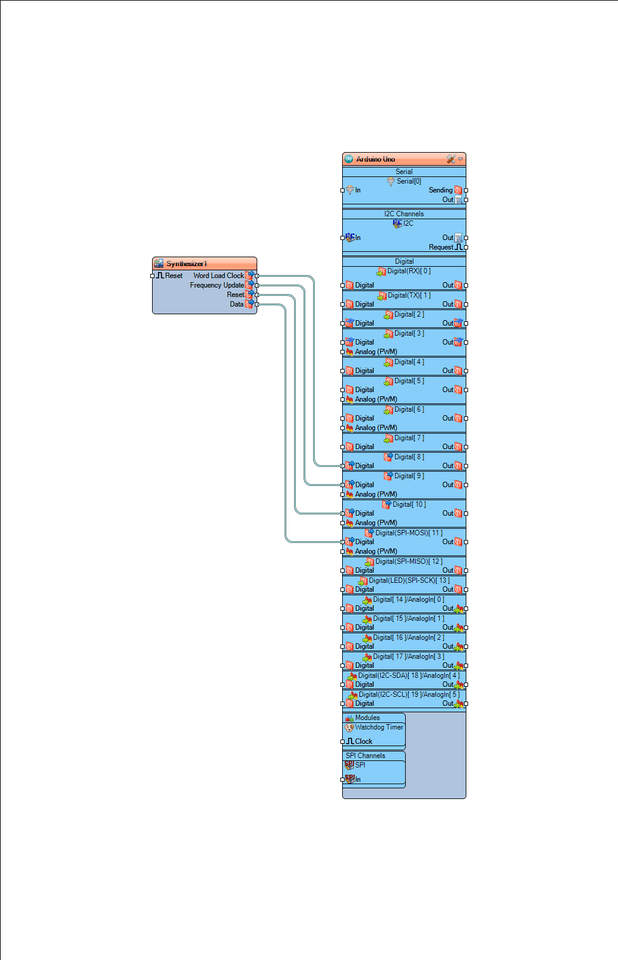
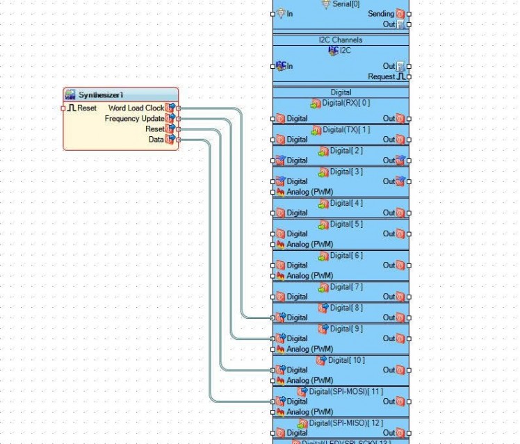
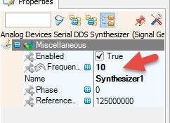
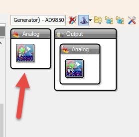
- Add "Analog Devices Serial DDS Synthesizer (Signal Generator) - AD9850" component
- Select "Synthesizer1" component and in the properties window under "Frequency (Hz)" set the desired frequency, in our case we set the frequency 10Hz
- Select "Synthesizer1" component and connect pin "Word Load Clock" to Arduino digital pin 8
- Select "Synthesizer1" component and connect pin "Frequency Update" to Arduino digital pin 9
- Select "Synthesizer1" component and connect pin "Reset" to Arduino digital pin 10
- Select "Synthesizer1" component and connect pin "Data" to Arduino digital pin 11
Step 6: Generate, Compile, and Upload the Arduino Code

In Visuino, at the bottom click on the "Build" Tab, make sure the correct port is selected, then click on the "Compile/Build and Upload" button.
Step 7: Play
If you power the Arduino UNO module, the AD9850 will start to put the frequency on the output pins, Square wave out on "SQ Wave Out 1" pin or Sine wave on "Sine Wave Out 1" pin.
Congratulations! You have completed your project with Visuino. Also attached is the Visuino project, that I created for this tutorial, you can download it and open it in Visuino: https://www.visuino.eu
Schematics, diagrams and documents
Code
Credits
Related products


Leave your feedback...